MOE Key Laboratory of Material Physics and Chemistry under Extraordinary Conditions, School of Chemistry and Chemical Engineering, Northwestern Polytechnical University, Xi'an 710072, China
b.
School of Chemistry and Chemical Engineering, North Minzu University, Yinchuan 750021, China
c.
State Key Laboratory of Efficient Production of Forest Resources, Beijing Key Laboratory of Lignocellulosic Chemistry, Beijing Forestry University, Beijing 100083, China
Received Date:
31 March 2025 Accepted Date:
19 May 2025 Revised Date:
11 May 2025 Available Online:
15 May 2026
Abstract:
Layered double hydroxides (LDHs) hold great promise for flexible solid-state supercapacitors owing to their high theoretical capacitance and distinctive architecture. However, their proneness to agglomeration and poor electrical conductivity have long hindered the manifestation of outstanding electrochemical performance. In a groundbreaking approach, we have engineered a hierarchical carbon nanofiber-based NiCo2S4/NiCo-LDH/C nanostructure array. The meticulously crafted hierarchical structure not only imparts remarkable stability to the electrode but also ingeniously harnesses the synergistic interplay among materials. Through density functional theory calculations, we have precisely identified and verified the active sites for charge transfer, unveiling a new understanding of the underlying mechanisms. This unique structure significantly facilitates ion transfer in the vicinity of NiCo-LDH, substantially elevates electrical conductivity, and notably increases the adsorption capacity of OH-. Moreover, it gives a substantial boost to the quantum capacitance. As a result, the electrode showcases a high specific capacitance of 1838.3 F/g. This research pioneers an effective and versatile strategy that can be readily applied to the majority of LDHs, opening up new avenues for enhancing their efficiency of supercapacitor materials.
At present, layered double hydroxides (LDHs) have become a promising electrode material for flexible supercapacitors due to their excellent electrochemical properties and tunable structures [1-3]. Supercapacitors have advantages such as high power density, long cycle life, and high efficiency. Introducing LDH into the electrode of supercapacitors can compensate for the disadvantages of traditional supercapacitors, such as high rigidity, excessive weight, and low energy density [4-7]. Thus, it can meet the requirements of modern energy storage devices for flexibility, light weight, and high energy density [8]. However, there are still two problems with LDHs at present: The layered structure of LDHs is prone to agglomeration, and its electrical conductivity is relatively poor [9,10]. To confront these challenges, a diverse range of strategies have been put forward, such as the nanostructure design, the modification via conductive polymers, the alteration with conductive carbon, as well as the doping of metal ions or non-metallic elements [11-15]. However, a compromise usually has to be struck among the structure and the function.
Designing the microstructure of electrode materials is an effective approach to enhance the depth of redox reactions and accelerate the charge transfer rate [16-18]. Specifically, a reasonable hierarchical structure can effectively combine the advantages of different materials to overcome the limitations of individual components, and this synergistic effect comprehensively enhances the electrochemical performance [5,19-22]. In addition, the interfaces at the junctions of these two phases usually lead to distortions, dislocations, and lattice defects, which can regulate the electronic structure, reduce the charge transfer resistance, and accelerate the kinetics of redox reactions [23-26]. In the traditional processes of electrode coating and current collectors, the electrodes are inflexible and have poor adaptability, and the presence of inactive materials increases the internal resistance of the electrodes [27,28]. Therefore, there is an urgent need to design a suitable hierarchical structure for LDH to overcome its inherent problems and apply it to flexible electrode materials, which is crucial for the development of wearable supercapacitors [29]. In addition, metal sulfides have abundant electrochemical active sites and high electrical conductivity. In particular, cobalt-based highly active bimetallic sulfides such as Co-M − S (where M = Ni, Fe, and Mn) possess variable oxidation states, which can facilitate the charge transfer in the hierarchical structure [30-32]. The diverse structures of sulfides can also serve as the basis for the design of hierarchical structures.
Herein, we selected melamine-modified carbon nanofibers with excellent performance as the flexible substrate (MCNF). And then, we in-situ grew an array of hollow nanoneedles of NiCo2S4 on the modified carbon nanofibers (MCNF@NiCo2S4). Subsequently, NiCo-LDH was directionally grown on the hollow nanoneedles (MCNF@NiCo2S4/NiCo-LDH). Finally, a conductive carbon layer was deposited on the surface through physical vapor deposition, resulting in the hierarchical MCNF@NiCo2S4/NiCo-LDH/C. And it demonstrated some advantages: (1) Flexible carbon nanofibers not only serve as a flexible substrate but also provide an electric double-layer capacitance (EDLC) and a continuous electron transport network. The integration of structure and function effectively eliminates the "dead volume" brought about by conductive additives and binders. (2) The hollow NiCo2S4 acts as the main backbone to support and regulate the growth position, size and orientation of NiCo-LDH. In addition, NiCo2S4 creates more and shorter paths for ion diffusion as a "conductive bridge". (3) The conductive carbon layer encapsulates the NiCo-LDH at the nanoscale, serving as both a protective net and a conductive network. The calculations of density functional theory (DFT) confirm the location where the charge transfer occurs, and the adsorption capacity of the electrode for OH-. In conclusion, this work explores the synergistic enhancement effect of the hierarchical structure on the structure and function of NiCo-LDH.
Fig. 1a illustrates the elaborate design and fabrication approach of the hierarchical MCNF@NiCo2S4/NiCo-LDH/C. All experimental schemes for the electrodes are presented as shown in Fig. S1 (Supporting information), the testing and characterization methods are described in Fig. S2 (Supporting information), and the calculation methods are illustrated in Fig. S3 (Supporting information).
Figure 1
Figure 1.
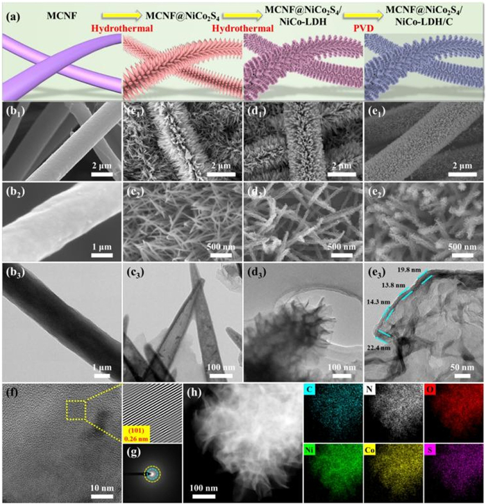
(a) The schematic illustration of the preparation of MCNF@NiCo2S4/NiCo-LDH/C. The SEM and TEM images of (b) MCNF, (c) MCNF@NiCo2S4, (d) MCNF@NiCo2S4/NiCo-LDH and (e) MCNF@NiCo2S4/NiCo-LDH/C. (f) The HRTEM images, (g) the SAED and (h) the EDS mapping of MCNF@NiCo2S4/NiCo-LDH/C.
The microstructure of the material was thoroughly investigated using scanning electron microscope (SEM) and transmission electron microscope (TEM) to validate its hierarchical structure. The carbon nanofibers were crafted through electrostatic spinning and carbonization, serving as flexible substrate. Among the three different modified carbon nanofiber membranes, namely MCNF, PCNF, and CNF, MCNF exhibits the best flexibility. Fig. 1b reveals that the MCNF fibers exhibit uniform thickness, a smooth surface, and a high aspect ratio. The uniform and interconnected NiCo2S4 nanoneedle are clearly visible in Fig. 1c, and NiCo2S4 vertically anchored on the MCNF. We acknowledge that the carbon nanofiber membrane is composed of stacked individual fibers. Electrons cannot be transferred between the fibers without contact points, and as a result, some of the fibers cannot form an interconnected conductive network. The introduction of hollow NiCo2S4 nanoneedles has greatly increased the contact points between the fibers, enhancing the possibility of electron transfer between the fibers, which leads to a decrease in the resistivity in the direction perpendicular to the fibers. Further TEM analysis shows that NiCo2S4 exhibits a hollow structure. The active materials inside the material often do not participate in the reaction or require a longer time for ion diffusion, which is unfavorable for the specific capacitance. The hollow structure eliminates this "dead volume", which is expected to increase the specific capacity of the electrode material [33]. As shown in Fig. 1d, the ultrathin thickness NiCo-LDH nanosheets grow on the hollow NiCo2S4 directionally and thereby increasing the specific surface area and charge storage capabilities [34,35]. After depositing a carbon layer on the surface, a stable protective carbon conductive shell is formed, and the average thickness is 17.6 nm (Fig. 1e). The introduction of the carbon layer alleviates the stress during the electrode using and the damage of the electrolyte to NiCo-LDH [36,37]. As depicted in Fig. 1f, the HRTEM image of the MCNF@NiCo2S4/NiCo-LDH/C reveals a stripe spacing of 0.26 nm, which corresponds to the (101) plane of NiCo-LDH.
In addition, the characteristic crystal plane (002) of C and the characteristic crystal plane (400), and (111) of NiCo2S4 are shown in Fig. S1 (Supporting information). And the SAED rings indicate the polycrystalline structure of the MCNF@NiCo2S4/NiCo-LDH/C (Fig. 1g). These rings correspond to the (101) and (012) planes [38]. Furthermore, the corresponding EDS mapping of the MCNF@NiCo2S4/NiCo-LDH/C demonstrates the uniform distribution of C, N, O, Ni, Co, and S throughout its support-encapsulation structure (Fig. 1h). In order to further characterize the crystal structure, the samples were tested by X-ray diffraction (XRD, Fig. 2a). The characteristic peak at 2θ = 23° is related to the C. And the peaks at 16.34°, 26.84° and 31.58° are the main characteristic peaks belong to NiCo2S4 that can be distinguished from NiCo LDH, representing stand for (111), (220) and (311) crystal faces (PDF #73–1704). And the peaks at 34.9° and 62.3° can be corresponded to the (012) and (113) planes of NiCo-LDH. The low crystallinity of hybrid arrays results in weak diffraction peaks, which is consistent with the lattice stripe data for HRTEM [39]. To delve deeper into the chemical characteristics of the material's surface, Raman spectroscopy measurements were conducted (Fig. 2b). The D peak at 1343 cm-1 reflects the carbon defects in the crystal lattice, and the G peak at 1599 cm-¹ reflects the degree of carbonization or graphitization [40]. An appropriate ratio of the D peak to the G peak is beneficial for the MCNF to achieve a balance among capacity, electrical conductivity, and flexibility. Furthermore, the peaks observed at 600 cm-1 can be ascribed to the F2g and A1g vibrational modes inherent to NiCo2S4 [41]. Within the MCNF@NiCo2S4/NiCo-LDH, two distinct peaks were identified at 459.9 and 546.2 cm-1, corresponding to the deformation and stretching vibrations of Matel-O and Matel-OH [42]. Additionally, the prominent peak at 1040 cm-1 is attributed to the M-O-M bonds characteristic of hydroxides [43]. The frequency of the MCNF@NiCo2S4/NiCo-LDH/C composite is observed to decrease, accompanied by an increase in the corresponding half-peak width, which corresponds to the weak crystal diffraction of SAED.
Figure 2
Figure 2.
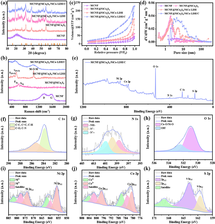
(a) The XRD pattern, (b) the Raman spectroscopy, (c) the BET and (d) the pore size distribution of MCNF, MCNF@NiCo2S4, MCNF@NiCo2S4/NiCo-LDH, and MCNF@NiCo2S4/NiCo-LDH/C. The XPS spectrum of MCNF@NiCo2S4-LDH@C: (e) Survey scan, (f) C 1s, (g) N 1s, (h) O 1s, (i) Ni 2p, (j) Co 2p, (k) S 2p.
The surface structure of the materials was meticulously evaluated through nitrogen adsorption-desorption measurements (BET, Figs. 2c and d). The specific surface areas (SSA) of MCNF, MCNF@NiCo2S4, MCNF@NiCo2S4/NiCo-LDH, and MCNF@NiCo2S4/NiCo-LDH/C were determined to be 42, 102, 175, and 244 cm2/g, respectively. A larger SSA can not only strengthen the contact between the electrolyte and the electrode but also enhance the EDLC [44,45]. Furthermore, the pore size distribution curves revealed that MCNF@NiCo2S4/NiCo-LDH/C possesses an abundance of large-sized mesopores, crucial for facilitating the swift movement of electrolyte ions [46,24].
The elemental composition and chemical state were analyzed by X-ray photoelectron spectroscopy (XPS) spectra (Figs. 2e-k). The Fig. 2e reveals distinct characteristic peaks corresponding to C, N, O, Ni, Co, and S elements. Within the C 1s spectrum (Fig. 2f), peaks at 285.3 and 284.8 eV are indicative of standard carbon peaks arising from thin carbon layers and MCNF. The N 1s has three distinct peaks at 401, 399.6, and 398.7 eV, which are attributed to graphitic, pyrrole, and pyridine nitrogen form MCNF (Fig. 2g). The O 1s spectrum exhibits two peaks (Fig. 2h), the peak at 530.9 eV attributed to the bond between metal and oxygen and the peak at 532.4 eV originating from OH- present in NiCo-LDH [47,48]. The spectra of Ni 2p and Co 2p exhibit clear distinctions between two spin-orbit splitting peaks (2p1/2 and 2p3/2) and their respective satellite peaks (Figs. 2i and j). Finally, the S 2p spectrum decomposes into two primary peaks and a satellite peak (Fig. 2k). The peaks centered at S 2p3/2 (161.5 eV) and S 2p1/2 (163.8 eV) correspond to surface low-coordinated sulfur ions and metal-sulfur bonding, respectively [3,41].
Based on the analysis presented above, the hierarchical MCNF@NiCo2S4/NiCo-LDH/C structure significantly enhances the structural stability and the density of the conductive network, providing a foundation for electrochemical performance. The electrochemistry performance of the electrodes is tested by a three-electrode system. The MCNF has the best flexibility and its cyclic voltammetry (CV) and galvanostatic charge-discharge (GCD) curves exhibit typical characteristics of EDLC (Fig. S2 in Supporting information). Compared with similar materials, MCNF also exhibits superior energy storage capabilities (Table S1 in Supporting information) [49-56]. In addition, the specific capacities of CNF@NiCo2S4, PCNF@NiCo2S4, MCNF@NiCo2S4 are 562, 579.2, and 915.8 F/g at 1 A/g, respectively (Fig. S3 in Supporting information). The MCNF@NiCo2S4 shows the maximum specific capacitance, which is related to the continuous conductive network and the regulation of the charge distribution on the carbon plane by N [57,58]. Furthermore, the GCD curves of the MCNF@NiCo2S4/NiCo-LDH-1, MCNF@NiCo2S4/NiCo-LDH-3, MCNF@NiCo2S4/NiCo-LDH-4, and MCNF@NiCo2S4/NiCo-LDH have special asymmetry indicates the pseudocapacitive behavior during the current decline (Figs. S3 and S4 in Supporting information). It can be observed from the specific capacitance results that the electrochemical performance is closely related to the ion ratio of Ni and Co, and the optimal Ni-Co ion ratio is 1:2 (Table S2 in Supporting information). In the experiments with different carbon layer thicknesses, it was found that a moderate thickness is beneficial to the electrochemical performance (Table S2 in Supporting information).
Fig. 3a illustrates the CV curves of the MCNF@NiCo2S4, MCNF@NiCo2S4/NiCo-LDH, and MCNF@NiCo2S4/NiCo-LDH/C at 40 mV/s and all the curves exhibit Faraday capacitive behavior. The MCNF@NiCo2S4/NiCo-LDH/C electrode demonstrates more pronounced redox peaks and confined area, suggesting excellent electrochemical performance relative to other electrodes [59]. The MCNF@NiCo2S4/NiCo-LDH/C electrode exhibits the best charging/discharging behavior, highlighting excellent charge storage energy. According to the formula, MCNF@NiCo2S4/NiCo-LDH/C electrode reaches an astonishing 1838.3 F/g (Fig. 3b). Even at a higher current density of 20 A/g, it can still provide a specific capacitance of 982.9 F/g, significantly exceeding the performance of the MCNF@NiCo2S4 and MCNF@NiCo2S4/NiCo-LDH (Fig. 3c). Fig. 3d presents the EIS curve of the electrode, which is analyzed to understand the reaction kinetics. The diameter of semicircle at the high-frequency reflects the charge transfer resistance (Rct). Notably, the MCNF@NiCo2S4/NiCo-LDH/C electrode exhibits the smallest Rct. Furthermore, the rapid ion diffusion and permeation result in an almost vertical straight line of the electrode in the low-frequency region [9]. This may be due to the efficient electron transfer near the NiCo-LDH [19]. In addition, the morphological features of MCNF@NiCo-LDH shows in Fig. S5 (Supporting information). Fig. S6 (Supporting information) presents a comparative analysis of the electrochemical performance between MCNF@NiCo-LDH/C and the ternary composite MCNF@NiCo2S4/NiCo-LDH/C. The calculated specific capacitance of MCNF@NiCo-LDH/C reached 1146 F/g at 1 A/g, demonstrating a 37.7% deficit compared to the ternary composite's superior capacitance of 1838.3 F/g under identical conditions. This performance gap is attributed to the enhanced ion diffusion kinetics and optimized charge transfer pathways in the ternary composite, as evidenced by electrochemical impedance spectroscopy (EIS) showing a Rct reduction in charge transfer resistance (from 0.034 Ω to 0.011 Ω). Furthermore, the MCNF@NiCo2S4/NiCo-LDH/C exhibited limited rate capability at high current densities, retaining only 68.2% of its initial capacitance (1254 F/g) when subjected to 20 A/g. The MCNF@NiCo2S4/NiCo-LDH/C electrode has a capacity retention of 85.1% (20,000 cycles at 1 A/g, Fig. 3e), demonstrating its long-term stability. The SEM and XRD images of the electrodes after cycling were analyzed (Fig. S7 in Supporting information), and the results show that the capacity decline is attributed to the degradation of the materials [60,61]. The (101) and other crystal planes of the material were damaged, and the MCNF was exposed, which was specifically manifested as the weakening of the relevant peaks and an increase in the peak intensity at 2θ = 23°. In comparison to previously reported LDH-based electrodes, the designed MCNF@NiCo2S4/NiCo-LDH/C electrode exhibited superior performance (Fig. 3f) [2,25,62].
Figure 3
Figure 3.
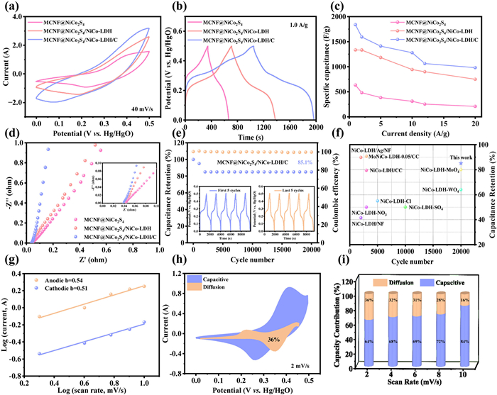
(a) The CV curves at 40 mV/s, (b) GCD curves at 1 A/g, (c) specific capacitance at different current density, (d) EIS curves of MCNF@NiCo2S4, MCNF@NiCo2S4/NiCo-LDH and MCNF@NiCo2S4/NiCo-LDH/C. (e) Cycle stability of MCNF@NiCo2S4/NiCo-LDH/C at 1 A/g and GCD curves of first and last 5 cycles. (f) Comparison of electrochemical properties with previously reported electrode materials. (g) Linear relationship between logi and logν of MCNF@NiCo2S4/NiCo-LDH/C at different potentials. (h) Capacitive and diffusion-controlled contribution to charge storage at 2 mV/s. (i) Capacitive and diffusion-controlled contributions ratios at different scan rates of the MCNF@NiCo2S4/NiCo-LDH/C.
The charge storage mode was further studied. Charge storage at the electrode typically involves two electrochemical processes, the capacitance-controlled and the diffusion-controlled. The b values of 0.54 (anodic) and 0.51 (cathodic) for MCNF@NiCo2S4/NiCo-LDH/C, obtained from fitted peak currents at different sweep rates, suggest reaction control by battery-type redox kinetics (Fig. 3g and Fig. S3.1 and in Supporting information) [63]. Additionally, the capacitive contribution was quantified, reaching 64% at 2 mV/s (Fig. 3h). Notably, the capacitive contribution of the well-designed MCNF@NiCo2S4/NiCo-LDH/C electrode exceeds that of other electrodes at different sweep speeds (Fig. 3i). The NiCo2S4 grows outward and acts as a bridge between carbon fibers, increasing the conductive channels on carbon nanofibers and significantly shortening the charge transfer distance [64]. The small and regular lamellae reduce the consumption of charge scattering transfer within NiCo-LDH, rapidly direct the remaining charge, and improve the charge transfer efficiency. In addition, the abundant redox reactions of NiCo2S4 provide a secondary driving force for charge transfer [65,66]. We measured the conductivity of the samples using a four-probe resistivity meter. The results show that the conductivities of the MCNF, MCNF@NiCo2S4, MCNF@NiCo2S4/NiCo-LDH, and MCNF@NiCo2S4/NiCo-LDH/C electrode materials are 0.6154, 2.173, 2.62, and 3.11 S/cm, respectively. The conductivitie of MCNF@NiCo-LDH/C is 1.51 S/cm. It is evident that the addition of hollow NiCo2S4 significantly enhances the speed of charge transfer.
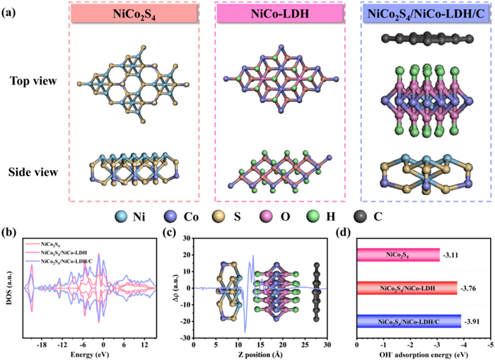
In pursuit of a deeper understanding of hierarchical structures, density functional theory (DFT) computations were conducted on NiCo2S4, NiCo2S4/NiCo-LDH, and NiCo2S4/NiCo-LDH/C. Fig. 4a presents the refined atomic structural models of these materials. The interfacial interactions were initially assessed through the density of states (DOS) and the differential charge density (S3.2 in Supporting information). The energy gap in Fig. 4b reveals an expansion of the bandgap within the Fermi level range, indicative of typical metallic attributes and elevated conductivity. And it indicates that the quantum capacitance of the material is enhanced due to the introduction of local states near the Fermi level. In contrast, the charge density at the Fermi level for NiCo2S4/NiCo-LDH/C exhibits a marked increase, signifying an intensified electronic transfer within the reaction dynamics [46]. Moreover, the differential charge density corroborates this enhancement (Fig. 4c), where electrons liberated from the redox reactions migrate from NiCo-LDH to NiCo2S4, converging until their Fermi levels.
Figure 4
Figure 4.
(a) Atomic structure models. (b) DOS of NiCo2S4, NiCo2S4/NiCo-LDH and NiCo2S4/NiCo-LDH/C. (c) Differential charge density of the interface between NiCo2S4 and NiCo-LDH. (d) Adsorption energies of OH−.
To further comprehend the electrochemical reactions within the KOH electrolyte, the adsorption energy of OH- on the materials was calculated (Fig. 4d). Notably, the support-encapsulation structure of NiCo2S4/NiCo-LDH/C demonstrates a higher OH- adsorption energy, indicating a robust capacity to capture alkaline electrolyte ions, thereby facilitating efficient OH- adsorption on the electrode surface and substantially enhancing the kinetics of redox reactions. These theoretical insights further reinforce the notion that the hierarchical structure excels in electrochemical performance due to its accelerated reaction kinetics. These are consistent with the predictions and further elaborate on the reaction kinetics.
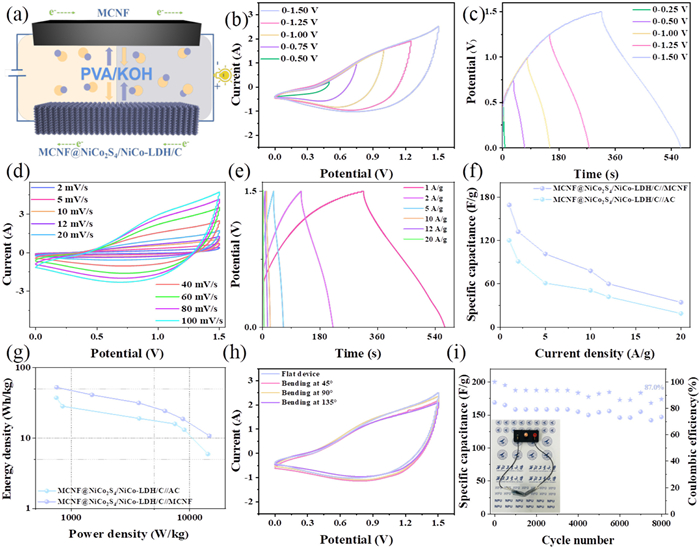
In the pursuit of practical applications, we prepared two all-solid-state asymmetric supercapacitors using activated carbon (AC) and MCNF as the counter electrodes for MCNF@NiCo2S4/NiCo-LDH/C respectively. The electrochemical performances of AC and MCNF@NiCo2S4/NiCo-LDH/C//AC are demonstrated in Figs. S8 and S9 (Supporting information). The electrochemical performance of MCNF@NiCo2S4/NiCo-LDH/C//MCNF is demonstrated in Fig. 5. There is no adhesive in the MCNF@NiCo2S4/NiCo-LDH/C//MCNF. To optimize the electrochemical performance of the ASC within a reliable potential window, CV (Fig. 5b) and GCD (Fig. 5c) were conducted at 40 mV/s and 1 A/g, respectively. And the working potential window of the ASC was precisely set to 0–1.5 V. Further exploration under this potential window at varying scan rates revealed that the CV curves remained stable even at a high rate of 100 mV/s (Fig. 5d). However, the redox peak is not pronounced and implies the influenced by EDLC of the AC electrode [67]. Accurate calculations determined that the specific capacitances of the ASC were 171.3 F/g at 1 A/g (Figs. 5e and f). To delve into the practical potential of the ASC, we conducted a thorough analysis of its energy and power densities. Ragone plots revealed that our designed ASC could deliver 53.5 Wh/kg at 754.5 W/kg, demonstrating its superior energy storage performance compared to other studies in the field (Fig. 5g) [52,68-70]. In line with the trend of modern electronic devices towards flexibility and wearables, we also assessed the performance stability of the ASC under different bending conditions. As shown in Fig. 5h and Fig. S10 (Supporting information), when the device is folded at different angles, there is no significant difference in the CV curves, demonstrating its excellent flexibility. The bending stability of the ASC was further explored (Fig. S11 in Supporting information), and during the bending test (0°−180°) with 200 cycles, the specific capacitance retention rate was 100%.
Figure 5
Figure 5.
(a) The schematic illustration of the ASC. (b) The CV curves at different potential windows. (c) The GCD curves at different potential windows. (d) The CV curves. (e) The GCD curves of the MCNF@NiCo2S4/NiCo-LDH/C//MCNF. (f) The specific capacitance at different current density of MCNF@NiCo2S4/NiCo-LDH/C//MCNF and MCNF@NiCo2S4/NiCo-LDH/C//AC. (g) The Ragone plots of MCNF@NiCo2S4/NiCo-LDH/C//MCNF and MCNF@NiCo2S4/NiCo-LDH/C//AC. (h) The CV curves at different bending angles. (i) Cycle stability of MCNF@NiCo2S4/NiCo-LDH/C//MCNF at 5 A/g and driving a light bulb.
This performance is attributed to the enhanced ion diffusion kinetics and optimized charge transfer pathways in the ternary composite, as evidenced by electrochemical impedance spectroscopy (EIS) showing a Rct reduction in charge transfer resistance (from 0.034 Ω to 0.011 Ω, Fig. S11). Furthermore, the MCNF@NiCo2S4/NiCo-LDH/C exhibited limited rate capability at high current densities, retaining only 68.2% of its initial capacitance (1254 F/g) when subjected to 20 A/g. Furthermore, the ASC maintained a capacitance retention of 87% after 8000 cycles (Fig. 5i). MCNF@NiCo2S4/NiCo-LDH/C//MCNF shows a higher specific capacitance, energy density and cycling stability than MCNF@NiCo2S4/NiCo-LDH/C//AC. Ultimately, the ASC device successfully powered a light bulb, confirming its potential and feasibility for practical applications.
In summary, the hierarchical MCNF@NiCo2S4/NiCo-LDH/C effectively improves the working efficiency of LDH. DFT calculations indicate that the structure significantly enhances ion transfer near NiCo-LDH, increases electrical conductivity and adsorption energy of OH-. As a result, the hierarchical structure endows the NiCo-LDH with structural stability and relieves the limitations on its electrochemical performance. The electrode showcases 1838.3 F/g and 53.5 Wh/kg. These efforts provide valuable insights into the application of LDH in advanced flexible supercapacitor.
Declaration of competing interest
The authors declare that they have no known competing financial interests or personal relationships that could have appeared to influence the work reported in this paper.
The authors acknowledge financial support from National Natural Science Foundation of China (No. 52072307). And the authors supported by the Doctorate Foundation of Northwestern Polytechnical University. We would also like to acknowledge Analytical & Testing Center of Northwestern Polytechnical University for the equipment support provided for FETEM (FEI Talos F200X) and SEM (FEI Verios G4).
Supplementary materials
Supplementary material associated with this article can be found, in the online version, at doi:10.1016/j.cclet.2025.111347.
Figure 1
(a) The schematic illustration of the preparation of MCNF@NiCo2S4/NiCo-LDH/C. The SEM and TEM images of (b) MCNF, (c) MCNF@NiCo2S4, (d) MCNF@NiCo2S4/NiCo-LDH and (e) MCNF@NiCo2S4/NiCo-LDH/C. (f) The HRTEM images, (g) the SAED and (h) the EDS mapping of MCNF@NiCo2S4/NiCo-LDH/C.
Figure 2
(a) The XRD pattern, (b) the Raman spectroscopy, (c) the BET and (d) the pore size distribution of MCNF, MCNF@NiCo2S4, MCNF@NiCo2S4/NiCo-LDH, and MCNF@NiCo2S4/NiCo-LDH/C. The XPS spectrum of MCNF@NiCo2S4-LDH@C: (e) Survey scan, (f) C 1s, (g) N 1s, (h) O 1s, (i) Ni 2p, (j) Co 2p, (k) S 2p.
Figure 3
(a) The CV curves at 40 mV/s, (b) GCD curves at 1 A/g, (c) specific capacitance at different current density, (d) EIS curves of MCNF@NiCo2S4, MCNF@NiCo2S4/NiCo-LDH and MCNF@NiCo2S4/NiCo-LDH/C. (e) Cycle stability of MCNF@NiCo2S4/NiCo-LDH/C at 1 A/g and GCD curves of first and last 5 cycles. (f) Comparison of electrochemical properties with previously reported electrode materials. (g) Linear relationship between logi and logν of MCNF@NiCo2S4/NiCo-LDH/C at different potentials. (h) Capacitive and diffusion-controlled contribution to charge storage at 2 mV/s. (i) Capacitive and diffusion-controlled contributions ratios at different scan rates of the MCNF@NiCo2S4/NiCo-LDH/C.
Figure 4
(a) Atomic structure models. (b) DOS of NiCo2S4, NiCo2S4/NiCo-LDH and NiCo2S4/NiCo-LDH/C. (c) Differential charge density of the interface between NiCo2S4 and NiCo-LDH. (d) Adsorption energies of OH−.
Figure 5
(a) The schematic illustration of the ASC. (b) The CV curves at different potential windows. (c) The GCD curves at different potential windows. (d) The CV curves. (e) The GCD curves of the MCNF@NiCo2S4/NiCo-LDH/C//MCNF. (f) The specific capacitance at different current density of MCNF@NiCo2S4/NiCo-LDH/C//MCNF and MCNF@NiCo2S4/NiCo-LDH/C//AC. (g) The Ragone plots of MCNF@NiCo2S4/NiCo-LDH/C//MCNF and MCNF@NiCo2S4/NiCo-LDH/C//AC. (h) The CV curves at different bending angles. (i) Cycle stability of MCNF@NiCo2S4/NiCo-LDH/C//MCNF at 5 A/g and driving a light bulb.

 DownLoad:

 下载:
下载:


 下载:
下载:
