School of Materials Science & Engineering, Beijing Institute of Technology, Beijing 100081, China
b.
Advanced Research Institute of Multidisciplinary Science, Beijing Institute of Technology, Beijing 100081, China
c.
Tsinghua Center for Green Chemical Engineering Electrification & Beijing Key Laboratory of Complex Solid State Batteries, Department of Chemical Engineering, Tsinghua University, Beijing 100084, China
* Corresponding author at: School of Materials Science & Engineering
Received Date:
15 March 2025 Accepted Date:
15 May 2025 Revised Date:
09 May 2025 Available Online:
15 July 2026
Abstract:
Lithium–sulfur (Li–S) battery is considered as a promising next-generation high-energy-density battery. However, the cycle life of Li–S batteries is severely plagued by the instability of Li metal anodes. Improving Li deposition uniformity can mitigate the formation of inactive Li and the side reactions between Li polysulfides and Li metal anodes. Herein, 1-methyl-1-propylpyrrolidinium bis(fluorosulfonyl)imide (Py13FSI) is proposed as an additive to improve the uniformity of Li deposition in Li–S batteries. At a low concentration, Py13+ exhibits a lower reduction potential than Li ions. Py13+ can be adsorbed and accumulate on the surface protuberances of Li metal anodes, inducing the deposition of Li towards non-tip sites and improving the uniformity of Li deposition. With a high-loading cathode (4.1 mgS/cm2) and an ultrathin Li metal anode (50 µm), the cycle life of Li–S batteries is prolonged from 61 to 120 cycles via Py13FSI additives. Furthermore, a 401 Wh/kg Li–S pouch cell with Py13FSI additives undergoes 14 cycles. This work demonstrates the potential of improving Li deposition uniformity in Li–S batteries by appropriate electrolyte additives.
The burgeoning demand for portable electronic devices and electric vehicles has drawn unprecedented attention to the development of high-energy-density rechargeable batteries [1]. Lithium–sulfur (Li–S) battery is regarded as one of the most promising next-generation high-energy-density batteries due to the ultrahigh energy density of over 400 Wh/kg [2,3]. However, Li–S batteries suffer from short cycle life under demanding conditions including employing a high-sulfur-loading cathode (> 4.0 mgS/cm2), a low electrolyte-to-sulfur ratio (E/S ratio, < 7.0 µL/mgS), and a limited Li metal inventory (< 100 µm), which severely limits the practical applications of Li–S batteries [4-6].
The instability of Li metal anodes, which originates from non-uniform Li deposition, is a leading factor limiting the cycle life of Li–S batteries [7,8]. The non-uniform deposition of Li results in the formation and accumulation of inactive Li, leading to the rapid depletion of limited active Li reservoirs during cycles [9-13]. In addition, notorious side reactions happen between soluble Li polysulfides (LiPSs) and Li metal anodes in Li–S batteries [14-16]. The side reactions can be accelerated by non-uniformly deposited Li with a large specific surface area, which further induces the loss of active materials rapidly [7]. Consequently, it is imperative to improve Li deposition uniformity to stabilize Li metal anodes and prolong the cycle life of Li–S batteries.
Electrolyte design is an effective strategy to improve Li deposition uniformity [17-19]. Primary electrolyte design includes increasing the concentration of Li salts and the use of electrolyte additives [20-24]. High-concentration electrolytes (HCE) and localized high-concentration electrolytes (LHCE) that can form anion-derived solid electrolyte interphase (SEI) in Li metal batteries have garnered widespread attention [25-27]. Nevertheless, in Li–S batteries, the increase in salt concentration decreases the amount of free solvent for LiPSs solvation, which reduces the solubility of LiPSs and leads to a reduction in specific capacity and a loss in energy density. In contrast, the use of electrolyte additives is considered as a more effective strategy for electrolyte design because it can regulate the interface of Li metal anodes without change in the basic properties of the electrolyte [28-30]. Li nitrate (LiNO3) additive has been widely used to improve the uniformity of Li metal anodes in Li–S batteries due to the formation of LiNxOy-containing SEI [31-33]. However, the solubility of LiNO3 in electrolytes is insufficient [34]. Thus, isosorbide dinitrate (ISDN) with increased solubility and reactivity is proposed, which constructs LiNxOy-rich SEI and induces more uniform Li deposition [35]. In addition to LiNxOy, as an effective inorganic component in SEI, LiF can enhance the transport uniformity of Li ions in SEI and further improve Li deposition uniformity [36,37]. Consequently, fluoroethylene carbonate (FEC) is commonly employed as a co-solvent or additive to form LiF-rich SEI [38-40]. However, FEC is incompatible with Li–S batteries due to the nucleophilic reactions between LiPSs and FEC [41]. In addition to regulating the components of SEI, additives such as CsPF6 can build an electrostatic shielding layer at the Li metal anode/electrolyte interface to promote uniform Li deposition [42,43]. However, PF6− is not suitable for Li–S batteries due to the severe side reactions between LiPSs and PF6− [44]. Although certain additives have the capacity to improve the uniformity of Li deposition, they are incompatible with Li–S batteries or the effect is far from satisfactory. Therefore, it is necessary to develop specialized additives to improve Li deposition uniformity in Li–S batteries.
Herein, 1-methyl-1-propylpyrrolidinium bis(fluorosulfonyl)-imide (Py13FSI) is proposed as an additive in Li–S batteries to improve the stability of Li metal anodes and avoid the decrease in cathode conversion kinetics. Py13+ has a lower reduction potential than Li ions (−3.04 V vs. standard hydrogen electrode, SHE) and can be adsorbed and accumulate on the surface protuberances of Li metal anodes [45]. Consequently, an electrostatic shielding layer is formed via Py13FSI additives, which induces the deposition of Li towards non-tip sites, improves Li deposition uniformity and further mitigates the formation of inactive Li and the side reactions between LiPSs and Li metal anodes. By using Py13FSI additives, a prolonged cycle life of Li–S batteries from 61 cycles to 120 cycles is achieved under demanding conditions including high-sulfur-loading cathodes (4.1 mgS/cm2), low E/S ratio (6.4 µL/mgS), and ultrathin Li metal anodes (50 µm). Furthermore, a 3.47 Ah pouch cell with Py13FSI additives, reaching an initial energy density of 401 Wh/kg, undergoes stable 14 cycles.
Ionic liquids (ILs) are selected as electrolyte additives due to their advantages such as low volatility, high thermal stability, non-flammability, and wide electrochemical window [46-49]. ILs have been previously employed as cosolvents or electrolyte additives in Li–S batteries to improve the stability of Li metal anodes mainly by reducing the solubility of LiPSs or generating stable SEI [50,51]. However, the battery performance in previous works was tested under mild conditions and the effect of ionic liquids under demanding conditions is unclear. In this work, the ratio of ILs is < 5% in volume to avoid the problems of high viscosity and elevated expense and prevent the reduction in cathode conversion kinetics. Thus, Py13FSI is used as an electrolyte additive (Fig. 1a and Table S1 in Supporting information) for the following considerations. 1-Methyl-1-propylpyrrolidinium cation (Py13+) is stable and can act as an electrostatic shielding layer for its low reduction potential [45,52,53]. The S–F bond in the bis(fluorosulfonyl)imide anion (FSI−) can be easily broken to produce LiF, which is considered as a promising component in SEI to improve Li deposition uniformity [54,55]. To prove the effectiveness of Py13FSI additives, the baseline electrolyte consisting of 1.0 mol/L bis-(trifluoromethanesulfonyl) imide (LiTFSI) and 2.0 wt% LiNO3 in 1,3-dioxolane (DOL)/1,2-dimethoxyethane DME (1:1, v/v) is employed (denoted as DOL/DME electrolyte), which is the commonly used ether-based electrolyte in Li–S batteries [56,57]. The ratio of Py13FSI in DOL/DME electrolyte is limited to 2 and 5 vol% and the corresponding electrolyte is marked as 2 and 5 vol% Py13FSI electrolyte.
Figure 1
Figure 1.
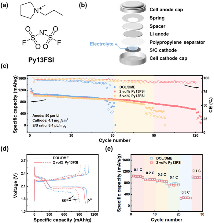
Electrochemical performance of Li−S coin cells with Py13FSI additives. (a) The molecular structure of Py13FSI. (b) Schematic diagram of a Li–S coin cell. (c) Cycling performance of Li–S batteries with DOL/DME electrolyte, 2 vol%, and 5 vol% Py13FSI electrolyte at 0.1 C under demanding conditions. (d) The corresponding galvanostatic charge–discharge profiles at the 5th and 55th cycles. (e) Rate performance of Li–S coin cells with DOL/DME electrolyte and 2 vol% Py13FSI electrolyte.
To evaluate the cycling performance of Li–S batteries with Py13FSI additives, Li–S coin cells were assembled (Fig. 1b). Under demanding conditions including high-sulfur-loading cathodes (4.1 mgS/cm2), low E/S ratio (6.4 µL/mgS), ultrathin Li metal anodes (50 µm), and a cycling rate of 0.1 C (1 C = 1672 mA/g), Li–S batteries with DOL/DME electrolyte and 5 vol% Py13FSI electrolyte deliver 61 and 90 cycles based on 50% capacity retention, respectively (Fig. 1c and Fig. S1 in Supporting information). In contrast, the Li–S battery with 2 vol% Py13FSI electrolyte undergoes stable 120 cycles based on 50% capacity retention, which is twice that of the Li–S battery with DOL/DME electrolyte (Fig. S2 in Supporting information). Given that 2 vol% Py13FSI is the optimal concentration, subsequent research mainly focuses on 2 vol% Py13FSI electrolyte. At the 5th cycle, the charge–discharge profiles of Li–S batteries with DOL/DME electrolyte and 2 vol% Py13FSI electrolyte are similar, indicating that the additive of Py13FSI has no harm on cathode kinetics (Fig. 1d). Li–S batteries with DOL/DME electrolyte and 2 vol% Py13FSI electrolyte deliver the same second discharge plateau voltage of 2.09 V and exhibit similar specific capacities of 1067 and 1026 mAh/g at the 5th cycle, respectively. At the 55th cycle, the Li–S battery with 2 vol% Py13FSI electrolyte still has a high specific capacity of 903 mAh/g, and the second discharge plateau voltage is 2.06 V with only a low voltage drop of 0.03 V. In contrast, for the Li–S battery with DOL/DME electrolyte, the specific capacity reaches only 837 mAh/g and the second discharge plateau voltage drops to 1.97 V after 55 cycles. The increased polarization of the battery with DOL/DME electrolyte indicates the rapid consumption of active Li and electrolytes and the accumulation of inactive Li [9,11,58]. Furthermore, the Li–S battery with 2 vol% Py13FSI electrolyte maintains a specific capacity of 616 mAh/g at the 110th cycle and the second discharge plateau voltage remains at 2.03 V (Fig. S3 in Supporting information), indicating the superior cycling stability.
In addition, the rate performance of 2 vol% Py13FSI electrolyte was evaluated. The Li–S battery with 2 vol% Py13FSI electrolyte has a specific capacity close to that of DOL/DME electrolyte at 0.1, 0.2, 0.3, 0.4, and 0.5 C, respectively (Fig. 1e and Fig. S4 in Supporting information). As the rate increases, the specific capacity decreases but recovers when the rate returns to 0.1 C, suggesting that 2 vol% Py13FSI electrolyte can work effectively at different rates and has virtually no negative effect on cathode conversion kinetics.
To verify the effectiveness of Py13FSI additives in improving Li deposition uniformity, the cycled Li–S batteries were disassembled to investigate the Li deposition behaviors by scanning electron microscope (SEM). The deposited Li in the DOL/DME electrolyte exhibits a loose and porous morphology at the 5th cycle (Fig. 2a). In contrast, the deposited Li is homogeneous and compact in 2 vol% Py13FSI electrolyte (Fig. 2b and Fig. S5 in Supporting information). After 40 cycles, non-uniform Li deposition, random cracks, and Li dendrites can be clearly observed on the anode cycled in the DOL/DME electrolyte (Fig. 2c). The cycled Li metal anode in the battery with 2 vol% Py13FSI electrolyte is denser and more homogeneous, demonstrating the improvement of Li deposition uniformity (Fig. 2d and Fig. S6 in Supporting information).
Figure 2
Figure 2.
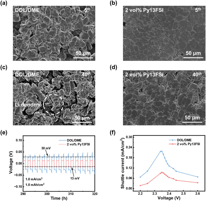
The deposition morphology and stability of Li metal anodes in different electrolyte systems. The surface morphologies of deposited Li in Li–S batteries with (a) DOL/DME electrolyte and (b) 2 vol% Py13FSI electrolyte at the 5th cycle under demanding conditions. The surface morphologies of deposited Li in Li–S batteries with (c) DOL/DME electrolyte and (d) 2 vol% Py13FSI electrolyte at the 40th cycle under demanding conditions. (e) Partial enlarged image of voltage profiles of Li|Li symmetric cells with different electrolytes. (f) Shuttle current at various potentiostatic voltages with different electrolytes after 10 cycles.
The positive effect of improving Li deposition uniformity was further confirmed. Li|Li symmetric cells containing 1.0 mol/L[S] Li2S8 were tested at a current density of 1.0 mA/cm2 and an areal capacity of 1.0 mAh/cm2. The symmetric cell with 2 vol% Py13FSI electrolyte exhibits smaller polarization during cycling than the cell with DOL/DME electrolyte. Specially, the polarization exhibits a decrease from 30 mV to 13 mV between 290 h and 320 h (Fig. 2e). Additionally, the symmetric cell with 2 vol% Py13FSI electrolyte exhibits a longer cycle life of 370 h compared with 270 h of the cell with DOL/DME electrolyte, indicating that the stability of Li metal anodes is enhanced in 2 vol% Py13FSI electrolyte (Fig. S7 in Supporting information).
Uniform Li deposition can reduce the reaction area between LiPSs and Li metal anodes [59]. Therefore, the effect of Py13FSI additives on mitigating the parasitic reactions between LiPSs and Li metal anodes was investigated. Shuttle current tests were conducted at different voltages to quantitatively characterize the shuttle effect [60,61]. After 10 cycles, a shuttle current of 0.218 mA/cm2 is observed in the Li–S battery with DOL/DME electrolyte when it reaches its peak at 2.35 V. In contrast, the shuttle current is < 0.095 mA/cm2 in the Li–S battery with 2 vol% Py13FSI electrolyte, indicating the side reactions between LiPSs and Li metal anodes are mitigated (Fig. 2f). To exclude the influence of Py13FSI additives on the solvation structure of LiPSs, Raman spectroscopy was further measured with different electrolytes containing 1.0 mol/L[S] Li2S8. Similar results are observed in Raman spectroscopy. DOL/DME electrolyte and 2 vol% Py13FSI electrolyte exhibit the same signal from LiPSs (392, 448, and 510 cm−1), DME (842 cm−1), and DOL (942 cm−1) [62,63], corroborating that Py13FSI additives do not affect the solvation structure of LiPSs (Fig. S8). These results effectively illustrate the extended cycle life of the Li–S battery is benefited from the improvement of Li deposition uniformity by 2 vol% Py13FSI.
To investigate the working mechanism of Py13FSI additives, the reduction potential of pyrrolidine/Py13+ and Li/Li+ were estimated and the components on the Li metal anodes were analyzed in different electrolytes. The electrostatic shielding effect requires that the effective reduction potential (φRed(M/M+)) of certain cations (M+) is lower than that of Li ions (φRed(Li/Li+), −3.04 V vs. SHE) [42]. According to the Nernst equation:
$
\varphi_{\text {Red }}=\varphi^{\ominus}{ }_{\text {Red }}-R T \ln \left(\alpha_{\text {Red }} / \alpha_{\mathrm{Ox}}\right) / z F
$
(1)
where the standard reduction potential (φRed⊖(pyrrolidine/Py13+)) of Py13+ is −3.16 V vs. SHE [45], R is the molar gas constant (8.314 J/(mol·K)), T is the temperature (assume T = 298.15 K in this work), z is the number of moles of electrons transferred (the value of z corresponds to 1 during the reduction of Py13+ to pyrrolidin), F is the Faraday constant (96,485 C/mol), and α is the chemical activity for the relevant species (αRed is for the reductant and αOx for the oxidant). αx = γxcx, where γx and cx are the activity coefficient and the concentration of species x. In the case of a low concentration of Py13FSI additives (2 vol%), αx can be simplified to equal the concentration cx.
Given that the corresponding molar concentration of 2 vol% Py13FSI is 87 mmol/L, Eq. 2 can be obtained.
If the φRed(pyrrolidine/Py13+) is −3.04 V vs. SHE, the value of cRed is approximately equal to 0.8 mmol/L by combining Eqs. 1 and 2. This indicates that when < 1% of Py13+ is reduced, the φRed(pyrrolidine/Py13+) can be lower than φRed(Li/Li+) at the Li+ concentration of 1.0 mol/L. Therefore, Py13+ can stably exist on the Li metal anode/electrolyte interface and fulfill the premise of the electrostatic shielding effect.
To confirm the working mechanism of Py13FSI additives, X-ray photoelectron spectroscopy (XPS) was employed. The N 1s spectra display noticeable differences between DOL/DME electrolyte and 2 vol% Py13FSI electrolyte. Li3N and LiNxOy are the decomposition products of LiTFSI and LiNO3, which can be observed in the N 1s spectrum of the DOL/DME electrolyte (Fig. 3a). After the introduction of Py13FSI additives, an extra peak appears at 403.4 eV in 2 vol% Py13FSI electrolyte at the sputtering time of 0 s, corresponding to Py13+ (Fig. 3b). Furthermore, the N atomic content on Li metal anodes increases to 2.0% and 1.3% (at sputtering times of 0 and 60 s, respectively) in 2 vol% Py13FSI electrolyte, compared with 0.7% and 1.0% in DOL/DME electrolyte, respectively (Fig. S9 in Supporting information), indicating the existence of Py13+ on the Li metal anode/electrolyte interface. In F 1s spectra, there is nearly no difference (Fig. S10 in Supporting information), and there is no increase on the F atomic content in 2 vol% Py13FSI electrolyte (Fig. S11 in Supporting information), which eliminates the possibility that the improvement of Li deposition uniformity can be attributed to the formation of LiF-rich SEI.
Figure 3
Figure 3.
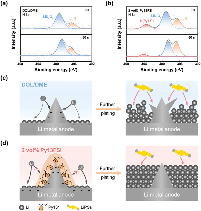
The working mechanism of Py13FSI. XPS spectra of N 1s of Li metal anodes disassembled from cycled Li–S batteries with (a) DOL/DME electrolyte and (b) 2 vol% Py13FSI electrolyte after 5 cycles. Schematic diagrams of Li deposition progress in Li–S batteries with (c) DOL/DME electrolyte and (d) 2 vol% Py13FSI electrolyte.
The working mechanism of Py13+ is then summarized. During the initial Li deposition stage, some protuberant tips inevitably form. The tips of the electrode have a stronger electric field, resulting in the preferential deposition of Li on the tips. This behavior leads to the formation of Li dendrites and the non-uniformity of Li deposition, which further increases the reaction area between LiPSs and Li metal anodes (Fig. 3c). With the introduction of Py13FSI additives, Py13+ is adsorbed and accumulates on the surface protuberances of Li metal anodes, inducing the deposition of Li towards non-tip sites. Based on the electrostatic shielding effect, the inert Py13+ effectively improves Li deposition uniformity and mitigates the formation of inactive Li and the side reactions between LiPSs and Li metal anodes (Fig. 3d).
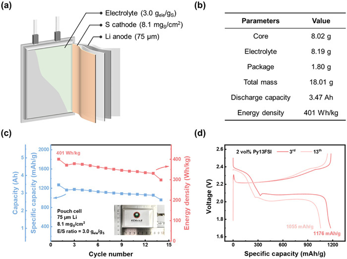
In order to validate the feasibility of 2 vol% Py13FSI electrolyte in practical high-energy-density batteries, a 3.47 Ah Li–S pouch cell was assembled under practical conditions [4]. The Li–S pouch cell was assembled with dimensions of 4 cm × 7 cm and stacks of double-sided Li metal anodes and S cathodes. The pouch cell used high-sulfur-loading S cathodes of 8.1 mgS/cm2, a low E/S ratio of 3.0 gele/gS, and ultrathin Li anodes of 75 µm (Fig. 4a). The Li–S pouch cell delivers an initial specific capacity of 1270 mAh/g and an initial discharge energy density of 401 Wh/kg based on the total mass of 18.01 g (Fig. 4b). After 14 stable cycles, the Li–S pouch cell with 2 vol% Py13FSI electrolyte maintains a specific capacity of 961 mAh/g and an energy density of 300 Wh/kg with a high retention of 75% (Fig. 4c). The charge–discharge profiles of the Li–S pouch cell with 2 vol% Py13FSI electrolyte exhibit typical two discharge plateaus, indicating that the kinetics of the solid-liquid-solid conversion reaction are well preserved (Fig. 4d). A dip at the second discharge plateau is observed during cycling due to electrolyte exhaustion [64]. The effect of Py13FSI additives in high-energy-density Li–S pouch cells demonstrates the potential of prolonging the cycle life of Li–S batteries by improving Li deposition uniformity based on the electrostatic shielding effect.
Figure 4
Figure 4.
Cycle performance of Li–S pouch cells. (a) Schematic illustration of a Li–S pouch cell. (b) Parameters of a Li–S pouch cell with 2 vol% Py13FSI electrolyte. The core includes Li metal anodes, S cathodes, Cu current collectors, Al current collectors, PP separators, and taps. (c) Cycling performance and (d) the corresponding galvanostatic charge–discharge profile at the 3rd and 13th cycles of a Li–S pouch cell with 2 vol% Py13FSI electrolyte at 0.05 C. The inset in (c) is the optical image of the corresponding pouch cell.
In conclusion, Py13FSI is proposed as an electrolyte additive in Li–S batteries to improve Li deposition uniformity and stabilize Li metal anodes without interference on cathode conversion kinetics. Py13+ has a lower reduction potential than Li ions and can be adsorbed and accumulate on the surface protuberances of Li metal anodes, inducing the deposition of Li towards non-tip sites, improving Li deposition uniformity, and further mitigating the formation of inactive Li and the side reactions between LiPSs and Li metal anodes. Consequently, under demanding conditions including high-sulfur-loading cathodes (4.1 mgS/cm2), low E/S ratio (6.4 µL/mgS), and ultrathin Li metal anodes (50 µm), a prolonged cycle life of Li–S batteries from 61 cycles to 120 cycles is achieved via Py13FSI additives. Furthermore, the feasibility of 2 vol% Py13FSI electrolyte is demonstrated in a 3.47 Ah pouch cell that has an initial energy density of 401 Wh/kg and can undergo 14 stable cycles. This work inspires the feasibility of improving Li deposition uniformity by appropriate electrolyte additives for high-energy-density and long-cycling Li–S batteries.
Declaration of competing interest
The authors declare no competing financial interests or personal relationships that could have appeared to influence the work reported in this paper.
This work was supported by National Key Research and Development Program (No. 2021YFB2400300), National Natural Science Foundation of China (Nos. 22309100, 22425901, and 22379013), Tianjin Natural Science Foundation (No. 23JCZDJC00130), and relevant national projects.
Supplementary materials
Supplementary material associated with this article can be found, in the online version, at doi:10.1016/j.cclet.2025.111330.
Figure 1
Electrochemical performance of Li−S coin cells with Py13FSI additives. (a) The molecular structure of Py13FSI. (b) Schematic diagram of a Li–S coin cell. (c) Cycling performance of Li–S batteries with DOL/DME electrolyte, 2 vol%, and 5 vol% Py13FSI electrolyte at 0.1 C under demanding conditions. (d) The corresponding galvanostatic charge–discharge profiles at the 5th and 55th cycles. (e) Rate performance of Li–S coin cells with DOL/DME electrolyte and 2 vol% Py13FSI electrolyte.
Figure 2
The deposition morphology and stability of Li metal anodes in different electrolyte systems. The surface morphologies of deposited Li in Li–S batteries with (a) DOL/DME electrolyte and (b) 2 vol% Py13FSI electrolyte at the 5th cycle under demanding conditions. The surface morphologies of deposited Li in Li–S batteries with (c) DOL/DME electrolyte and (d) 2 vol% Py13FSI electrolyte at the 40th cycle under demanding conditions. (e) Partial enlarged image of voltage profiles of Li|Li symmetric cells with different electrolytes. (f) Shuttle current at various potentiostatic voltages with different electrolytes after 10 cycles.
Figure 3
The working mechanism of Py13FSI. XPS spectra of N 1s of Li metal anodes disassembled from cycled Li–S batteries with (a) DOL/DME electrolyte and (b) 2 vol% Py13FSI electrolyte after 5 cycles. Schematic diagrams of Li deposition progress in Li–S batteries with (c) DOL/DME electrolyte and (d) 2 vol% Py13FSI electrolyte.
Figure 4
Cycle performance of Li–S pouch cells. (a) Schematic illustration of a Li–S pouch cell. (b) Parameters of a Li–S pouch cell with 2 vol% Py13FSI electrolyte. The core includes Li metal anodes, S cathodes, Cu current collectors, Al current collectors, PP separators, and taps. (c) Cycling performance and (d) the corresponding galvanostatic charge–discharge profile at the 3rd and 13th cycles of a Li–S pouch cell with 2 vol% Py13FSI electrolyte at 0.05 C. The inset in (c) is the optical image of the corresponding pouch cell.

 DownLoad:

 下载:
下载:


 下载:
下载:
