Co-Innovation Center of Efficient Processing and Utilization of Forest Resource School of Materials Science and Engineering, Nanjing Forestry University, Nanjing 210037, China
Received Date:
08 March 2025 Accepted Date:
15 May 2025 Revised Date:
01 May 2025 Available Online:
15 August 2026
Abstract:
The emergence of aqueous K/Zn dual-ion batteries has opened a promising new frontier in energy storage by leveraging the high energy density of zinc-ion batteries (ZIBs) and the voltage enhancement provided by cation intercalation mechanisms. However, the lifespan of these batteries has been significantly limited by dendrite growth and side reactions at the zinc negative electrode. To address this challenge, we successfully fabricated an organic framework, Zn-MOF-74, in-situ on the surface of the zinc negative electrode. The large-pore, one-dimensional channel structure of Zn-MOF-74 effectively enhances electrolyte permeability, reduces steric hindrance, and promotes efficient battery operation. Moreover, the open metal sites in Zn-MOF-74 effectively suppress side reactions, further improving battery performance. Notably, the average CE remained remarkably high at 99.43% after 1000 cycles. Furthermore, the Zn-MOF-74@Zn//ZnHCF configuration demonstrated exceptional cycling stability, retaining 88% of its initial capacity even after 1000 cycles at a current density of 1 A/g.
Aqueous zinc-ion batteries, known for being environmentally friendly and reliable, have garnered significant attention [1,2]. However, zinc-ion batteries face significant volumetric changes due to strong electrostatic interactions between divalent Zn2+-ions and the cathode material structure [3]. To address this issue, zinc dual-ion battery (ZDIB) has been introduced, which utilizes the co-insertion mechanisms of alkali/Zn2+-ions, which reduces the electrostatic interaction between the cations and the host material, leading to improved performance. Within this context, K/Zn dual-ion batteries have emerged as a notable frontier in research by integrating high-energy Zn batteries with the enhanced operating voltage afforded by cation intercalation.
During the working cycle of K/Zn dual-ion batteries, under the influence of the "tip effect" areas with larger curvatures can trigger higher surface charge densities, resulting in greater nucleation forces for Zn near the tips. Combined with the differences in growth speed or growth orientation, the dendrite growth trend becomes increasingly strong. As Zn accumulates, it ultimately punctures the separator, causing a battery short circuit [4]. Furthermore, Zn dendrites are characterized by an abundance of low-coordination Zn atoms and defective lattices, which exacerbate the catalytic activity towards hydrogen evolution reactions (HER) and accelerate the consumption of Zn. The soft and porous structure of these dendrites tends to detach from the electrode, leading to the formation of inactive or "dead" zinc deposits [5–7]. Therefore, it is imperative to devise innovative material structural designs that can substantially elevate the performance and stability of the zinc anode, ultimately culminating in the development of a dendrite-free and highly dependable battery system [8].
Currently, metal/metal oxides [9], polymers [10], organic-inorganic hybrid materials [11], and metal-organic framework (MOF) materials are commonly used as coating materials to modify negative electrodes. MOFs are porous and expandable frameworks formed by the coordination of metal cation centers with organic ligands [12]. The high degree of synthetic tunability in terms of shape and size, combined with the accessibility of organic groups within MOFs, facilitates the creation of pore arrangements that support directed ion transport pathways. In-situ growth, an unconventional bottom-up approach, involves the direct chemical formation of metal ions on a target substrate material without any preliminary colloidal synthesis steps. Since nanoparticles are formed directly on the substrate, self-assembly, ligand exchange, and other time-consuming processes can potentially be circumvented [13]. Xin [14] and Cui [15] constructed a porous and dense MOF layer in-situ on a binder-free Zn sheet using a hydrothermal method, which serves as an ideal substrate for zinc deposition to address the challenges of the zinc anode. Furthermore, some studies have indicated that MOF layers with insufficient thickness can be unstable in water, potentially accelerating anode corrosion [16]. Therefore, the morphology and properties of the MOF layers are critical for developing highly efficient and durable zinc anodes.
In this study, we selected Zn-MOF-74 as the target for in-situ growth to address the challengs of hydrogen evolution and dendrite formation in zinc anodes. These organic ligands coordinate with adjacent metal ions through their carboxylic acid groups, ensuring the stability and uniformity of the entire framework [17]. Utilizing the zinc ions provided by the zinc foil as the metal center, these ions coordinate with five oxygen atoms from the surrounding ligands to form an octahedral structure, Zn4O(COO)6 (Fig. S1 in Supporting information). Because these pores are aligned along the crystal axis of the material, a hexagonal channel network with a diameter of approximately 11 Å is generated. Unlike the polyhedral structure of ZIF, Zn-MOF-74 features a unique rod-like structure that can grow more rapidly on the zinc anode. Its high-density open metal sites can interact with the electrolyte, enhancing the permeability of zinc sheets, reducing steric hindrance, and facilitating rapid electron transfer [18]. We prepared Zn-MOF-74 powder mixed with PVDF (labeled as Zn-MOF-74/Zn, Fig. S2 in Supporting information), and Zn foil coated with Zn-MOF-74 (labeled as Zn-MOF-74@Zn). In tests, the Zn-MOF-74@Zn//Cu half-cell exhibited a cycle life exceeding 1000 h, with an average coulombic efficiency (CE) of 99.43%. The Zn-MOF-74@Zn//ZnHCF full cell demonstrated a high specific capacity of 70.3 mAh/g at a current density of 1 A/g and retained 88% of its capacity after 1000 cycles.
Preparation of Zn-MOF-74@Zn sample: 2.255 g of 2,5-dihydroxyterephthalic acid (H4dhtp) is dissolved in a mixed solution composed of 48.165 g of N,N-dimethylformamide (DMF), 2.655 g of anhydrous ethanol and 3.375 g of deionized water, and transfer to 100 mL autoclave after full stirring. The polished Zn was protected with Kapton tape on one side. In the stainless-steel autoclave of polytetrafluoroethylene, the zinc tablets (0.1 mm) react at 110 ℃ for 22 h. After cooling to room temperature, the sample is washed with DMF three times, soaked in methanol for 72 h (change methanol every 24 h), and finally stored in a 60 ℃ oven for 12 h to obtain the sample.
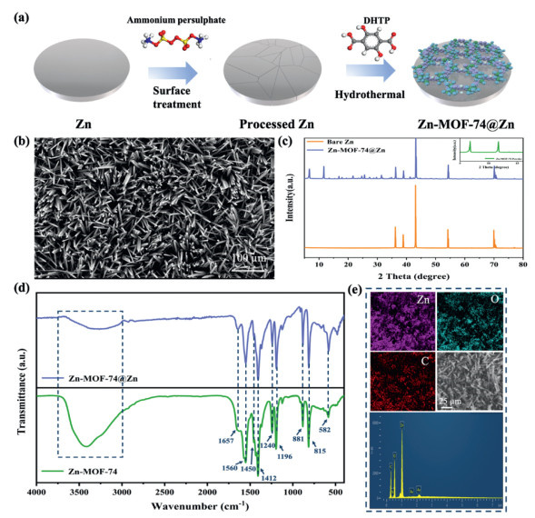
As illustrated in Fig. 1a, Zn-MOF-74 was synthesized directly through a streamlined, one-step process. The corrosive action of ammonium persulfate induced the formation of minute cracks across the otherwise smooth surface of the zinc sheet, thereby creating favorable conditions for the subsequent growth of the MOF. Following the growth process, SEM analyses were conducted on the samples (Fig. 1b), the MOF layer exhibiting the thickness of approximately 50 µm (Fig. S3 in Supporting information). Furthermore, Fig. S4 (Supporting information) illustrates the pore size distribution of Zn-MOF-74@Zn, revealing an average pore diameter of 7.2461 nm, with mesopores having an average diameter of 5.2217 nm. In the XRD pattern (Fig. 1c), the Zn-MOF-74 powder displays distinct diffraction peaks at approximately 2θ = 6.6° and 11.6° (Fig. S5 in Supporting information), corresponding to the (210) and (300) crystal planes [19]. The characteristic peaks observed for Zn-MOF-74@Zn were consistent with those of Zn-MOF-74, confirming the successful in-situ synthesis of Zn-MOF-74 on the zinc sheet. In the spectral analysis of the Zn-MOF-74 powder and Zn-MOF-74@Zn (Fig. 1d). The C-O-Zn vibration is evidenced by absorption peaks at 815 and 881 cm-1. A peak near 1196 cm-1 signifies the presence of C-O vibration, while the peak at 1240 cm-1 suggests C-N vibration, indicating that DMF may be adsorbed on the surface of the MOFs [20]. In addition, the peaks at 1560 and 1657 cm-1 correspond to the symmetric and asymmetric vibrations of the carboxyl C=O groups in the H4dhtp aromatic ring, respectively, indicating the involvement of organic ligands. The spectrum of Zn-MOF-74 also displays a broad band in the range of 2700–3600 cm-1, which signifies the -OH stretching of carboxylic acid within the MOF structure [21]. The broader peak observed in the Zn-MOF-74 powder in this region may be attributed to the adsorption of or residual water on the material's surface. Energy dispersive spectroscopy (EDS) mapping (Fig. 1e) confirmed the presence of C, O, and Zn. SEM image of the Zn-MOF-74 powder is presented in Fig. S6 (Supporting information).
Figure 1
Figure 1.
(a) Schematic illustration of the preparation process of Zn-MOF-74@Zn. (b) SEM image of Zn-MOF-74@Zn. (c) XRD patterns of the bare Zn, Zn-MOF-74 powder, and Zn-MOF-74@Zn. (d) FTIR of the synthesized Zn-MOF-74 powder and Zn-MOF-74@Zn. (e) Elemental mapping of Zn-MOF-74@Zn nanoparticles.
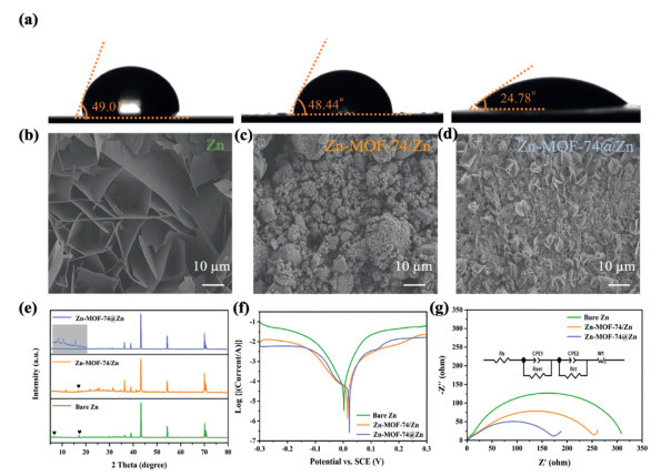
We compared the contact angles of three different materials, as illustrated in Fig. 2a. The bare zinc exhibited a contact angle of 49.01°. The Zn-MOF-74/Zn's contact angle decreased slightly, which can be attributed to the introduction of ligands containing a large density of hydrophilic carboxyl and hydroxyl groups, while the lower activation energy (Fig. S7 in Supporting information) allows Zn-MOF-74@Zn to exhibit excellent charge transfer properties. To further corroborate the inhibitory effect of the Zn-MOF-74 layer on the formation of by-products, we immersed bare zinc, Zn-MOF-74/Zn, and Zn-MOF-74@Zn in the electrolyte for 24 h and subsequently conducted observation tests. The SEM images presented in Figs. 2b-d demonstrate that the surface of Zn-MOF-74@Zn exhibits a smoother and more uniform morphology compared to the irregular particles observed on the surface of Zn-MOF-74/Zn. In contrast, the surface of bare zinc undergoes significant degradation, characterized by the formation of numerous flake-like dendrites. Additionally, the XRD spectrum shown in Fig. 2e, almost no characteristic peaks of the by-product (i.e., ZnxOTFy(OH)2x-y·nH2O) for Zn-MOF-74@Zn after soaking [22]. This indicates that the Zn-MOF-74 layer, which adheres tightly to the zinc surface in aqueous electrolytes, not only ensures good interface integrity but also inhibits the growth of zinc dendrites on the anode due to its open framework and well-defined channels. To accurately assess its corrosion resistance, the corrosion potential was evaluated through Tafel plots (Fig. 2f). The corrosion current of Zn-MOF-74@Zn is 0.37 mA, which is lower than that of bare zinc at 0.42 mA. This lower corrosion current indicates a reduced corrosion rate, suggesting that the Zn-MOF-74 layer can inhibit the corrosion reaction of Zn2+-ions during the electrochemical process [23]. The corrosion potential of Zn-MOF-74@Zn exhibits a positive shift, indicating enhanced corrosion resistance and HER performance compared to bare zinc and Zn-MOF-74/Zn [24]. The lower onset HER potential of Zn-MOF-74@Zn, derived from linear sweep voltammetry (LSV), further supports these findings (Fig. S8 in Supporting information). The microporous structure and open metal sites of Zn-MOF-74 can efficiently adsorb ions from the electrolyte, thereby altering the charge distribution on the electrode surface. This change in charge distribution may be detrimental to the hydrogen evolution reaction, as the rate and efficiency of the reaction largely depend on the nature of the charge on the electrode surface.
Figure 2
Figure 2.
(a) Dynamic contact angles of the electrolyte on the surfaces of bare Zn, Zn-MOF-74/Zn, and Zn-MOF-74@Zn. SEM images of (b) Zn, (c) Zn-MOF-74/Zn, and (d) Zn-MOF-74@Zn anodes after 24 h of infiltration in the electrolyte. (e) XRD results for the three anodes after soaking in electrolyte. (f) Tafel polarization curves. (g) EIS results of the three anodes.
Furthermore, as illustrated in Fig. 2g, the Nyquist plot reveals that in the ultra-high-frequency range (above 10 kHz), the ohmic resistance associated with the transport of Zn2+-ions and electrons through the electrolyte appears as a single point on the EIS spectrum. This phenomenon can be represented by a single resistance element, designated as Rs [25]. The fitted data indicate that the Rs of Zn-MOF-74@Zn in the initial stage is higher (2.313 Ω) compared to that of the bare zinc foil (1.268 Ω). This increase can be attributed to the ingress of Zn2+-ions into the MOF channels. The semi-circular arc in the high-frequency range reflects the impedance of ions traversing the electrolyte (Rsei), while the semi-circular arc in the low-frequency range represents the charge transfer resistance (Rct). The Rsei of the bare zinc foil is 10.9 Ω, and the Rct is 300.5 Ω. In contrast, for the Zn-MOF-74@Zn anode, a significant reduction in Rct to 159.1 Ω is observed. This decrease is attributed to the availability of more active sites for zinc deposition and improved electrolyte accessibility, facilitating the penetration of Zn2+-ions into the porous Zn-MOF-74 layer. Furthermore, the Zn-MOF-74@Zn physical model demonstrates arc resistance in the ultra-high-frequency region, resulting in a double-semicircle impedance plot. This indicates that the coating possesses corrosion-resistant properties, with the separated physical layer providing protection against corrosion [26]. However, the Rsei of Zn-MOF-74/Zn increases significantly to 20.24 Ω compared to bare zinc foil. This rise can be attributed to the incorporation of PVDF, which not only reduces the conductivity of the electrode but also increases the impedance between Zn-MOF-74 particles and the electrolyte, as well as among the particles themselves. Consequently, this elevates the internal resistance of the entire battery, significantly impacting the diffusion of Zn2+-ions at the anode-electrolyte interface. Additionally, the coating may thicken at the edges of the zinc electrode, resulting in an uneven surface that can exacerbate the occurrence of side reactions [27].
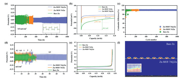
Fig. 3a illustrates the long-term plating/stripping cycles of the symmetric battery at a current density of 0.5 mA/cm2. During the 180-h test, a short circuit triggered by dendrite formation was observed in the bare zinc battery. In contrast, the battery coated with Zn-MOF-74 failed after approximately 350 h, likely due to the binder obstructing the pores of the MOF [16] and the unstable attachment between the coating and the zinc substrate. In stark contrast, the Zn-MOF-74@Zn battery has undergone stable cycling for over 1000 h, indicating that Zn-MOF-74@Zn effectively regulates the uniform Zn2+-ions flux, suppresses dendrite formation, and benefits from strong bonding through chemical interactions, which extends the lifespan of the symmetric battery. The enlarged voltage profiles within the figure reveal the details of zinc deposition/stripping on different substrates. Notably, Zn-MOF-74@Zn exhibited a lower voltage hysteresis of 55 mV. However, the moderate current densities of 0.5 mA/cm2 are insufficient for rigorous testing of the zinc electrode [28]. Therefore, we conducted charge-discharge tests under more rigorous conditions of 1 mA/cm2 and 0.5 mAh/cm2, as well as 10 mA/cm2 and 5 mAh/cm2, to evaluate the stability of the Zn-MOF-74@Zn symmetric battery (Figs. S9 and S10 in Supporting information). Under the testing condition of 10 mA/cm2, the Zn-MOF-74@Zn demonstrated a highly stable voltage profile and relatively low voltage hysteresis (76 mV) (Figs. S11 and S12 in Supporting information). The functionalized pores containing oxygen-rich functional groups in Zn-MOF-74@Zn facilitate the deposition of zinc ions [29].
Figure 3
Figure 3.
(a) Time-voltage curves at 0.5 mA/cm2 with a plating capacity of 0.25 mAh/cm2. (b) Nucleation overpotentials of bare Zn, Zn-MOF-74/Zn, and Zn-MOF-74@Zn deposition on bare Cu in asymmetric batteries. (c) CE of three electrodes during plating/stripping on Cu foil at 0.5 mA/cm2. (d) Rate capability of symmetrical batteries. (e) Potential profiles of these three electrodes after 60 cycles. (f) Schematic view of dendrite growth of electrodeposited Zn on these two electrodes using the phase-field model.
The zoomed-in curves in Fig. 3b illustrate the voltage profiles during the zinc deposition process [30]. A higher nucleation overpotential results in a lower deposition rate and efficiency [31], which can lead to the formation of larger and more inhomogeneous crystals within the deposition layer, ultimately affecting the structural stability and lifespan of the Zn foil. The nucleation overpotential of Zn-MOF-74@Zn (57.6 mV) is significantly lower than that of bare zinc (181.1 mV) and Zn-MOF-74/Zn (104.7 mV). This indicates that the transport channels within the in-situ grown MOF active layer effectively prevent the ingress of excessive free water, thereby enhancing the electrolyte concentration and ion transport speed at the anode surface. Consequently, this alleviates charge accumulation on the electrode surface. The porous structure and large specific surface area of the material provide more Zn2+-ions nucleation sites, facilitating more uniform zinc nucleation and leading to even and controlled zinc plating. The abundant hydrophilic groups interact with zinc ions, accelerating ion diffusion. However, the potential agglomeration of Zn-MOF-74/Zn coatings may adversely affect battery reversibility [32]. In contrast, Zn foil exhibits a higher overpotential, which tends to promote instantaneous nucleation. This can result in the formation of irregular and porous deposits, exacerbating the unevenness of the transport interface and increasing the likelihood of irreversible side reactions and dendrite growth [33]. The utilization of Zn is a crucial factor in determining its applications and long-term durability [34]. Initially, stripping was performed under conditions with a set zinc plating capacity of 0.25 mAh/cm2 and a cut-off potential of 0.5 V (Fig. 3c). At a current density of 0.5 mA/cm2, the initial CE of Zn-MOF-74-modified Zn was slightly lower than that of the bare Zn foil (75.12% vs. 76.41%). The lower CE observed for the Zn-MOF-74@Zn//Cu configuration is attributed to the porous structure of the Zn-MOF-74 coating, which consumes a greater amount of Zn. Ultimately, the Zn//Cu battery failed after approximately 100 cycles due to the formation of dendrites and by-products on the zinc surface [35]. In contrast, the Zn-MOF-74@Zn//Cu battery maintained an average CE of 99.43% (Fig. S13 in Supporting information), confirming the excellent reversibility of the Zn-MOF-74@Zn electrode and its rapid Zn2+-ions kinetics.
Figs. S14-S16 (Supporting information) illustrates the stable overpotential exhibited by the Zn-MOF-74@Zn//Cu battery during cycling. In contrast, the bare Zn//Cu battery experiences a sharp voltage increase exceeding 1 V, accompanied by significant fluctuations, which suggests instability in Zn2+-ions deposition/stripping on the Cu foil. Furthermore, the Zn-MOF-74/Zn//Cu battery also fails after 260 cycles. The reversibility of the modified anode was evaluated through Zn plating/stripping tests conducted at different current densities (Fig. 3d). The Zn-MOF-74@Zn anode successfully withstood the challenging conditions of 3.0 mA/cm2 and continued to cycle for an additional 50 cycles at 0.5 mA/cm2. This outcome demonstrates that the enhanced diffusion kinetics of Zn2+-ions within the Zn-MOF-74@Zn structure significantly improved the critical current capacity of the battery, allowing it to meet higher operational demands. Furthermore, the Zn-MOF-74@Zn//Cu exhibits a minimal overpotential of 46 mV (Fig. 3e), which is lower than that of the Zn//Cu (76 mV) and slightly less than the Zn-MOF-74/Zn//Cu (48 mV). The results further confirm that the incorporation of MOF layer pores on the surface of zinc foil can effectively enhance the stability and rate performance of Zn negative electrodes.
Fig. 3f depicts the growth mechanism of zinc dendrites on uncoated zinc electrodes. The emergence of dendrites is ascribed to the deposition of Zn2+-ions. Initially, zinc atoms diffuse freely across the electrode surface towards favorable nucleation sites, thereby initiating secondary reactions and surface obstruction. This sequence of events exacerbates the concentration polarization of Zn2+-ions, prompting active nucleation sites to elongate towards the electrolyte solution, which in turn diminishes the accessibility of nucleation sites. Consequently, Zn2+-ions are increasingly reduced and accumulate at the electrode surface tips and surrounding existing zinc nuclei, ultimately culminating in the formation of zinc dendrites [36,37]. However, The open framework and three-dimensional configuration of Zn-MOF-74@Zn facilitate the swift diffusion of Zn2+-ions, enabling a uniform distribution of the electric field through the mitigation of the tip effect and the reduction of localized current densities [38]. Simultaneously, the porous Zn-MOF-74 increases nucleation sites, and a large number of hydroxyl and carboxyl groups exposed within the pores attract zinc ions for uniform deposition, effectively alleviating protrusions and dendrites on the Zn foil, and ensuring uniform Zn plating/stripping.
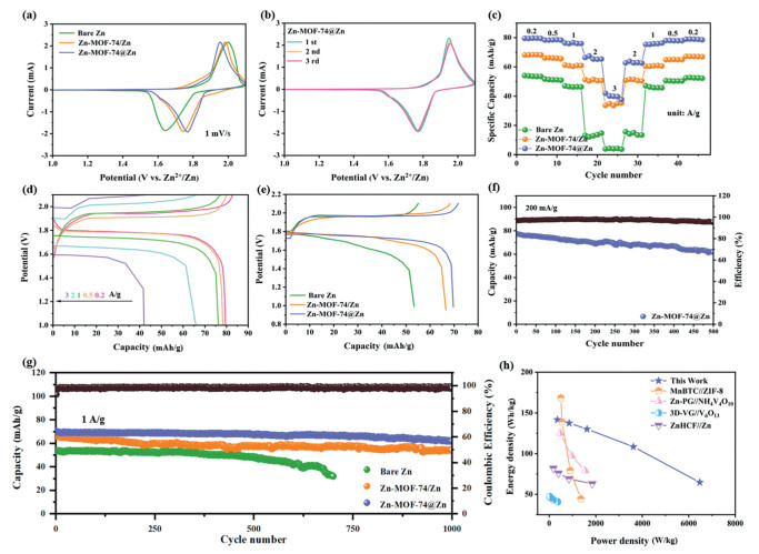
The ZnHCF cathode, with its large ion transport channels and stable structure, exhibits rapid ion diffusion kinetics and low impedance in a mild mixed aqueous electrolyte, making it one of the promising cathode materials for K/Zn dual-ion batteries [39,40]. Consequently, we have employed ZnHCF as the cathode to investigate the electrochemical performance of the full cell. Its microstructure and XRD are shown in Figs. S17 and S18 (Supporting information). Cyclic voltammetry (CV) curves obtained at a scan rate of 1 mV/s are presented in Fig. 4a. Notably, the Zn-MOF-74@Zn anode exhibits the smallest voltage separation (182 mV) between the oxidation and reduction peaks, outperforming both the Zn-MOF-74/Zn anode (238 mV) and bare Zn (353 mV). The CV curve of the Zn-MOF-74@Zn with in-situ growth exhibits stronger, more symmetric peak currents. This suggests accelerated Zn2+-ions diffusion within the Zn-MOF-74@Zn material, leading to higher anode interfacial charge transfer, increased Faraday reaction kinetics in the battery, and a significant reduction in polarization [41]. Compared to the control group, the Zn-MOF-74/Zn anode also exhibits significant improvements (Fig. S19 in Supporting information), indicating the crucial role of MOF-modified zinc anodes in enhancing battery performance. Furthermore, Fig. 4b compares the CV curves of the Zn-MOF-74@Zn//ZnHCF over the first three cycles, revealing a notable overlap [42]. At current densities of 0.2–3.0 A/g, the Zn-MOF-74@Zn exhibits discharge capacities of 79.5, 78.3, 76.3, 66.4, and 42.0 mAh/g, respectively (Fig. 4c). When the cycling current density is restored to 0.2 A/g, the capacity retention rate remains at 99.2%, indicating the Zn-MOF-74@Zn//ZnHCF exhibits excellent rate performance. The charge-discharge curves at corresponding current rates are displayed in Fig. 4d, exhibiting two distinct platforms during cycling. At a current of 1 A/g, the battery utilizing the Zn-MOF-74@Zn anode exhibits a specific capacity of 70.3 mAh/g (Fig. 4e). The Zn-MOF-74@Zn anode exhibits a high specific capacity of 77.3 mAh/g at a low current density of 0.2 A/g (Fig. 4f). After 500 cycles, it maintains a capacity retention rate exceeding 80% with the Coulombic efficiency greater than 97.39%. For long-cycle testing at a current density of 1 A/g (Fig. 4g, Figs. S20 and S21 in Supporting information), the capacity of the Zn anode continuously decreases during cycling, achieving a capacity retention rate of only 54.46% after 800 cycles [43]. In contrast, both the Zn-MOF-74@Zn and Zn-MOF-74/Zn exhibit capacity retention rates above 80% after cycling. This is attributed to the dense protective layer formed by Zn-MOF-74, which mitigates parasitic reactions. Due to the high reversibility of the Zn-MOF-74@Zn anode, the full battery demonstrates a low cycle capacity decay rate of 1.2% [44]. Zn-MOF-74@Zn demonstrates stronger adhesion and affinity, making it less prone to detachment from the zinc surface.
Figure 4
Figure 4.
(a) CV curves of three anodes. (b) CV curves of Zn-MOF-74@Zn//ZnHCF after three consecutive cycles. (c) Rate capability and (d) corresponding charge/discharge curves of the full cells with Zn-MOF-74@Zn anodes at different current densities. (e) First charge–discharge curve at 1 A/g. Cycling performance of the full cells at (f) 0.2 A/g and (g) 1 A/g. (h) Ragone plot of the Zn-MOF-74@Zn//ZnHCF cell. The energy and power densities of other anode materials reported in the literature are marked for comparison.
Based on the charge/discharge processes, the Zn-MOF-74@Zn demonstrates a high energy density of 141.69 Wh/kg at a power density of 354.2 W/kg. At an energy density of 64.76 Wh/kg, it achieves a maximum power density of 6.47 kW/kg, surpassing the performance of previously reported aqueous hybrid ion batteries (Fig. 4h) [39,45–47]. The Zn-MOF-74@Zn has low water content and abundant functional groups, which endow the anode with a robust structure and effectively suppress side reactions, inducing uniform deposition of zinc ions, thus achieving a long cycle life and high energy density. Fig. S22 (Supporting information) illustrates the surface morphology of the anode after 1000 cycles. The porous structure of Zn-MOF-74 facilitates easier infiltration of the electrolyte into the electrode, and the carboxyl and hydroxyl groups attract Zn2+-ions to migrate to the anode surface for deposition [48], resulting in a relatively uniform Zn plating layer, without sheet-like dendrites perpendicular to the electrode surface [49]. Figs. S23-S31 and Table S1 (Supporting information) prove the stability of the Zn-MOF-74@Zn.
In summary, we have achieved successful integration of Zn-MOF-74 onto zinc foil via an in-situ chemical bonding approach. The hydrophilic nature of Zn-MOF-74, coupled with its expansive pore size, markedly enhances the wettability of the zinc foil. This enhancement facilitates improved accessibility of electrolyte ions to the surface, thereby promoting uniform Zn2+-ions diffusion and ensuring an even charge distribution across the electrode. The modified Zn anode, exhibiting a reduced overpotential, effectively mitigates the formation of Zn dendrites and minimizes the occurrence of parasitic side reactions. Zn-MOF-74@Zn anode demonstrate superior capacity and extended cycling stability compared to those utilizing pristine zinc foil. Notably, in zinc plating and stripping experiments, Zn-MOF-74@Zn//Cu exhibited the Coulombic efficiency of 99.43%. These results underscore the significant potential of MOF-based anodes in the development of dendrite-free zinc-based batteries.
Declaration of competing interest
The authors declare that they have no known competing financial interests or personal relationships that could have appeared to influence the work reported in this paper.
The work at Nanjing Forestry University was supported by the Jiangsu Specially-appointed Professorship Program (No. Sujiaoshi [2016]20), National Natural Science Foundation of China (No. 31770608), and Jiangsu Agricultural Science and Technology Independent Innovation Fund Project (No. 164020154).
Supplementary materials
Supplementary material associated with this article can be found, in the online version, at doi:10.1016/j.cclet.2025.111326.
Z. Hou, H. Tao, J. Wang, L. Zhang, X. Yang, Sci. China Technol. Sci. 65 (2022) 2361–2368. doi: 10.1007/s11431-022-2117-9
Figure 1
(a) Schematic illustration of the preparation process of Zn-MOF-74@Zn. (b) SEM image of Zn-MOF-74@Zn. (c) XRD patterns of the bare Zn, Zn-MOF-74 powder, and Zn-MOF-74@Zn. (d) FTIR of the synthesized Zn-MOF-74 powder and Zn-MOF-74@Zn. (e) Elemental mapping of Zn-MOF-74@Zn nanoparticles.
Figure 2
(a) Dynamic contact angles of the electrolyte on the surfaces of bare Zn, Zn-MOF-74/Zn, and Zn-MOF-74@Zn. SEM images of (b) Zn, (c) Zn-MOF-74/Zn, and (d) Zn-MOF-74@Zn anodes after 24 h of infiltration in the electrolyte. (e) XRD results for the three anodes after soaking in electrolyte. (f) Tafel polarization curves. (g) EIS results of the three anodes.
Figure 3
(a) Time-voltage curves at 0.5 mA/cm2 with a plating capacity of 0.25 mAh/cm2. (b) Nucleation overpotentials of bare Zn, Zn-MOF-74/Zn, and Zn-MOF-74@Zn deposition on bare Cu in asymmetric batteries. (c) CE of three electrodes during plating/stripping on Cu foil at 0.5 mA/cm2. (d) Rate capability of symmetrical batteries. (e) Potential profiles of these three electrodes after 60 cycles. (f) Schematic view of dendrite growth of electrodeposited Zn on these two electrodes using the phase-field model.
Figure 4
(a) CV curves of three anodes. (b) CV curves of Zn-MOF-74@Zn//ZnHCF after three consecutive cycles. (c) Rate capability and (d) corresponding charge/discharge curves of the full cells with Zn-MOF-74@Zn anodes at different current densities. (e) First charge–discharge curve at 1 A/g. Cycling performance of the full cells at (f) 0.2 A/g and (g) 1 A/g. (h) Ragone plot of the Zn-MOF-74@Zn//ZnHCF cell. The energy and power densities of other anode materials reported in the literature are marked for comparison.


 DownLoad:

 下载:
下载:


 下载:
下载:

