Received Date:
21 February 2025 Accepted Date:
13 May 2025 Revised Date:
28 April 2025 Available Online:
15 August 2026
Abstract:
Sodium-based batteries (SBBs) are considered as promising next-generation energy storage devices owing to the low cost and natural abundance of raw materials. As the blood of SSBs, electrolytes are required to exhibit specific properties, including broad electrochemical stability windows, high thermal stability, prior ionic conductivity, and so on. Therefore, a diverse array of materials and compositions were developed to form novel electrolytes, thereby satisfying the practical requirements of SSBs. In this review, we comprehensively summarize the latest advances and the corresponding electrochemical properties of different electrolytes for SBBs. First, this review describes the desirable characteristics of electrolytes in detail. Subsequently, the latest progress in the design and regulation of electrolytes is systematically analyzed from four key aspects: organic liquid electrolytes, aqueous electrolytes, solid-state electrolytes, and quasi-solid-state electrolytes. Finally, this review delivers an exhaustive illustration on the challenges and research prospects concerning the further development of electrolytes in SBBs.
Energy scarcity problems are forcing researchers to develop new energy storage systems with high energy density and low cost. Among them, lithium-ion batteries become the most successful and prevalent one being widely utilized in various fields like portable electronic devices and electric vehicles [1]. However, the uneven distribution and complicated extraction process of lithium resources significantly restrict their further development. In contrast, with a theoretical specific capacity of 1165 mAh/g, metallic sodium (Na) can provide electrochemical performance close to that of lithium [2]. Moreover, sodium resources are more abundant in nature, which permits sodium-based batteries (SSBs) to be manufactured at a much lower cost than lithium-based batteries [3]. These advantages enable SBBs promising alternatives to lithium-based batteries [4].
The typical structure of sodium-based batteries (SBBs) consists of an anode, electrolyte, separator, and cathode, with commonly used anode materials including carbon-based materials, transition metal compounds, and alloyed materials [5]. As for cathode, representative materials, including layered oxides, polyanionic compounds, prussian blue analogs, sulfur composites, and air are commonly applied in SBBs [6]. Electrolytes in SBBs have functions of conducting electrons and transferring ions, which act as bridges connecting the electrodes. The role of the electrolytes is crucial, as they must ensure high ionic conductivity and stability under operating conditions. Therefore, the characteristics of the electrolytes can affect the properties of the batteries to a large extent [7,8]. At present, four main types of electrolytes have been investigated for applications to SBBs, namely organic liquid electrolytes, aqueous electrolytes, solid-state electrolytes, and quasi-solid-state electrolytes [9]. Generally, liquid-state electrolytes exhibit higher ionic conductivity compared to solid-state electrolytes because of their superior fluidity, which facilitates the rapid migration of Na+ ions [10]. In contrast, solid-state electrolytes offer enhanced safety due to their excellent thermal stability and broader electrochemical stability windows [11]. Aqueous electrolytes demonstrate high ionic conductivity, low cost, and exceptional safety. However, their energy density is significantly constrained by their limited range of operational voltage [12]. Consequently, various electrolytes can cater to diverse requirements, but all acquire targeted strategies to further improve their properties. To expedite industrialization, both organic liquid and aqueous electrolytes must achieve high energy density and long cycle life, while solid-state electrolytes need to realize improved ionic conductivity and interface properties [13]. In the future, certain ionic liquids and solid-state electrolytes may be regarded as promising candidates for viable SBBs, capable of operating under high voltage and elevated temperature conditions. However, the high cost associated with these electrolytes may impede their large-scale application in the near term [14]. As an innovative approach, the combination of different types of electrolytes can be employed to leverage their respective merits and mitigate their limitations [15]. In particular, solid-state electrolytes and liquid electrolytes, like ionic liquids, can be integrated to obtain quasi-solid-state electrolytes to address interfacial challenges and enhance compatibility within battery systems [16]. As research progresses, the design of electrolytes for SBBs necessitates a more comprehensive and systematic approach. The compatibility with advanced electrode materials, safety, and interfacial capability are often required to be collectively addressed within one electrolyte [17]. Therefore, the further design and optimization of electrolytes will be regarded as more and more critical for the next stage of the development of SBBs.
In this review, we systematically elucidate the characteristics, research progress, optimization strategies, and future prospects of electrolytes for SBBs. As shown in Fig. 1, the methods of improvement and modulation of different types of electrolytes and the desired excellent performances are summarized. It emphasizes the importance of targeted optimization strategies for various electrolytes, which are vital factors in achieving superior electrochemical performance and reliable safety. Varied electrolyte systems exhibit distinct electrochemical properties due to their varying electrochemical stabilities and the decomposition products formed during interactions with Na+ ions [18]. Consequently, we reviewed the development progress of organic liquid electrolytes, aqueous electrolytes, solid-state electrolytes, and quasi-solid-state electrolytes. Our aim is not only to analyze SBB electrolytes from an academic perspective but also to provide inspiration for future research through novel insights.
Figure 1
Figure 1.
Regulation methods and expected properties for different electrolytes on SBBs. Copied with permission [65]. Copyright 2018, American Chemical Society. Copied with permission [84]. Copyright 2020, Cell Press. Copied with permission [94]. Copyright 2017, Springer Nature. Copied with permission [118]. Copyright 2021, American Chemical Society. Copied with permission [112]. Copyright 2023, Springer Nature. Copied with permission [128]. Copyright 2020, Wiley-VCH. Copied with permission [168]. Copyright 2023, Wiley-VCH. Copied with permission [167]. Copyright 2024, Wiley-VCH. Copied with permission [172]. Copyright 2023, Springer Nature. Copied with permission [137]. Copyright 2023, Wiley-VCH. Copied with permission [154]. Copyright 2019, American Chemical Society. Copied with permission [151]. Copyright 2019, Elsevier.
2.
Targeting characteristics of sodium-based electrolytes
To advance sodium-based battery (SBB) technology, it is crucial to examine the key properties that electrolytes must exhibit to achieve optimal performance and practical applicability. This section delves into the essential attributes, encompassing chemical and electrochemical stability, thermal stability, ionic conductivity, compatibility and interfacial behavior with electrodes, non-toxicity and environmental benignity, as well as cost-effectiveness, which collectively underpin the development of superior SBB electrolytes, laying the groundwork for their integration into next-generation energy storage systems [19].
2.1
Chemical and electrochemical stability
Chemical and electrochemical stability are fundamental requirements for SBB electrolytes, as they critically affect the safety, efficiency, and longevity of the battery system. Chemical stability ensures the electrolyte's resistance to degradation or undesired reactions with electrode materials, separators, or the containers under ambient or operational conditions [20]. This is particularly important for preventing the formation of harmful byproducts, maintaining ionic conductivity, and sustaining overall battery performance [21]. Electrochemical stability, on the other hand, refers to the ability of the electrolyte to operate within a wide ESW, ensuring compatibility with high-voltage electrodes and minimizing side reactions such as electrolyte decomposition or parasitic reactions at the electrode-electrolyte interface [22].
The characterization and analysis of these properties are achieved through a range of experimental and computational techniques. Spectroscopic techniques, such as Fourier-transform infrared spectroscopy (FTIR) and nuclear magnetic resonance (NMR), are employed to identify degradation pathways and chemical changes in the electrolyte. Electrochemical stability is typically assessed by linear sweep voltammetry (LSV) to define the ESW, while cyclic voltammetry (CV) provides information on redox behavior and potential side reactions. Additionally, electrochemical impedance spectroscopy (EIS) offers insights into ion transport and interfacial stability. From a theoretical perspective, computational methods, such as density functional theory (DFT), complement experimental studies by predicting the reactivity and stability of electrolyte components under different conditions [23].
2.2
Thermal stability
Thermal stability is another important requirement for sodium-based electrolytes, especially for large-scale energy storage systems where operational safety is crucial. Thermal stability can be evaluated using thermogravimetric analysis (TGA) and differential scanning calorimetry (DSC). Electrolyte volatility must be minimized and decomposition at high temperatures, which often occurs during rapid charging, high current operation and thermal runaway, must be avoided. Thermally stable electrolytes reduce the risk of flammability and decomposition of the electrolyte, reducing safety risks such as electrolyte leakage, outgassing and explosions [24].
Conventional organic liquid electrolytes present thermal stability challenges due to the flammability of carbonate-containing solvents. Ionic liquid-based electrolytes composed of organic salts with low vapor pressure are usually thermally stable and non-flammable [25]. Solid electrolytes, especially superionic conductive sodium (NASICON) and sodium aluminum oxide, have much higher thermal stability, making them suitable candidates for safe SBBs [26].
2.3
Ionic conductivity
High ionic conductivity is necessary for high-efficiency transport of sodium ions in the electrolyte, providing high performance and low internal resistance in sodium-ion batteries. Ionic conductivity relies on the factors such as ion dissociation, ion mobility and the overall structure of the electrolyte [27]. Organic liquid electrolytes with sodium salts dissolved in organic solvents, such as NaClO4 and NaPF6, have ionic conductivities on the order of 10–3–10–2 S/cm at room temperature [28]. These values are comparable to lithium-ion based electrolytes and provide efficient charge transfer. However, the salt concentration and solvent composition need to be optimized to minimize viscosity and increase ion mobility [29].
Solid electrolytes have the advantage of stability, but often have a lower conductivity than liquid electrolytes, especially at room temperature. Ceramic electrolytes, such as NASICON, can achieve ionic conductivities close to 10–3 S/cm, but still need optimized efficiency to meet commercial standards [30]. Polymer electrolytes, including poly (ethylene oxide) (PEO)-based systems, offer customizable conductivity but are temperature dependent and require higher temperatures for optimum tolerance [31]. Quasi-solid-state electrolytes are therefore designed to combine the higher ionic conductivity with stability, becoming competitive candidates for the future SBB electrolytes.
2.4
Compatibility with electrodes and interface properties
The compatibility of sodium electrolytes with electrode materials is critical for achieving stable cycling performance, especially in high-capacity and high-rate sodium-based batteries (SBBs). The electrolyte must form a stable and homogeneous solid electrolyte interface (SEI) on the anode surface, which acts as a passivating layer to facilitate sodium-ion transport while preventing electrolyte degradation and dendrite formation [32,33]. For high-capacity anodes, such as alloy-based materials, the SEI layer must be mechanically robust to accommodate large volume changes during cycling. Electrolytes containing organic carbonates and sodium salts like NaPF6 and NaClO4 have been shown to influence SEI formation significantly, with additives like fluoroethylene carbonate (FEC) enhancing SEI stability and uniformity, thereby improving cycle life and rate performance [34].
In high-rate applications, the electrolyte must also ensure rapid ion transport and minimize interfacial resistance. For cathodes based on layered oxides or polyanionic compounds, the electrolyte must prevent undesirable side reactions, such as transition metal dissolution or the formation of insulating surface layers, which can degrade cathode performance at high currents [35,36]. Recent studies have demonstrated that localized high-concentration electrolytes (LHCEs) and ionic liquid-based electrolytes can suppress these side reactions while maintaining high ionic conductivity, enabling stable cycling at high rates. For example, LHCEs have been shown to improve the rate capability of Na3V2(PO4)3 cathodes by forming a stable cathode-electrolyte interphase (CEI) that minimizes metal dissolution and enhances sodium-ion diffusion [37,38]. These advancements highlight the importance of tailoring electrolyte formulations to meet the specific demands of high-capacity and high-rate electrode materials.
2.5
Nontoxicity and environmental sustainability
With increasing concern for the environment, sodium-based electrolytes must be non-toxic and environmentally friendly. The organic solvents and salts must be selected to minimize their environmental impact during manufacture, use and disposal. Research is underway to replace hazardous components such as fluorinated salts with environmentally friendly alternatives such as sodium bis(fluorosulfonyl)imide (NaFSI) or sodium trichloride (NaTf) [37].
In addition, aqueous electrolytes, including aqueous sodium ion systems, are gaining traction owing to their inherent safety, non-toxicity, and cost-effectiveness. These systems face challenges such as a narrow window for electrochemical stability, but advances in electrolyte additives and protective coatings have made significant progress towards practicality [38].
2.6
Cost-effectiveness
Finally, the cost-effectiveness of sodium-based electrolytes is also a crucial factor for the large-scale commercialization of SBBs. Sodium resources are abundant and geographically distributed, which is a clear advantage over lithium-based systems. Electrolyte components, including sodium salts and solvents, should be readily available and inexpensive to be produced on a large scale [39]. Solid electrolytes and ionic liquid-based systems are promising, but synthesis and processing costs must be reduced to compete with conventional liquid electrolytes [40].
3.
Regulation strategies of organic liquid electrolytes
The design of organic liquid electrolytes involves a delicate balance of multiple factors, including the interactions between solutes and solvents, as well as the incorporation of functional additives to address specific performance challenges. The regulation of solute-solvent structure delves into the fundamental mechanisms by which the interactions between sodium salts and organic solvents can be tailored to optimize electrolyte properties [41]. This includes a detailed analysis of sodium salt selection, concentration regulation, and the incorporation of ionic liquid electrolytes, each contributing to improved ionic conductivity, electrochemical stability, and compatibility with electrode materials [42]. The ability to finely tune these parameters is crucial for addressing the limitations of conventional liquid electrolytes and advancing the properties of SBBs [43].
We also examine the role of electrolyte additives in overcoming specific technical challenges. These include additives designed to inhibit sodium dendrite growth, which is vital for improving battery safety and preventing short circuits; additives that enhance the nonflammability of the electrolyte, thereby mitigating fire hazards; and additives engineered for wide-temperature applications, enabling reliable operation under extreme environmental conditions [44]. These approaches aim to expand the applicability and robustness of SBBs, paving the way for their widespread use in diverse energy storage scenarios.
3.1
Regulation of solute-solvent structure
The performance of SBB electrolytes is deeply influenced by the careful regulation of sodium salts, encompassing both their selection and concentration [45]. The selection of sodium salts makes a pivotal influence on determining the electrochemical stability, ionic conductivity, and compatibility of organic liquid electrolytes, with varied salts leading to distinct impacts on these key properties [46,47]. Beyond selection, the regulation of sodium salt concentration is equally important, as it directly shapes the solvated structure of sodium organic liquid electrolytes [48]. This includes the exploration of high-concentrated electrolytes and localized high-concentrated electrolytes, which have shown promise in improving ionic mobility, reducing solvent decomposition, and stabilizing electrode interface. By examining both the influence of varied sodium salts and the nuanced control of their concentrations, this section will provide a comprehensive overview on the strategies to optimize the performance of organic liquid electrolytes for advanced SBBs.
3.1.1
Selection of sodium salts
Sodium salts are essential for enabling the transport of Na+ ions between the anode and cathode during charge and discharge cycles, which is a vital determinant of the battery’s ionic conductivity, voltage stability, and overall efficiency. For an organic liquid electrolyte to function effectively, the sodium salt must exhibit high dissociation into Na+ ions, minimal ion-pair formation, and compatibility with the electrolyte’s solvent to facilitate rapid ion transport [49]. Moreover, the salt must possess a suitable electrochemical stability window, ensuring that it does not undergo decomposition or side reactions under typical operating conditions [50].
At present, there are two sodium salts which are commonly used in organic liquid electrolytes, NaPF6 and NaClO4. The complex and ambiguous internal mechanisms of micro-interface chemistry have prevented consensus on the most suitable sodium salts for high-performance sodium electrolytes, which hindered their further development. In order to reveal and compare the different interfacial chemical effects of NaPF6 and NaClO4, Cheng et al. dissolved NaClO4 and NaPF6 sodium salts in PC/EMC/DMC/FEC solvents for evaluation and comparison as electrolytes for sodium-ion batteries [51]. Through molecular dynamics (MD) calculations (Figs. 2a and b), combined with the analysis of corresponding radial distribution function (RDF) data, the NaPF6/EMC/DMC/FEC electrolyte exhibits characteristics of a typical solvent-separated ion pair structure. Both the solvent molecules and the PF6− anions participate in the primary Na+ solvation sheath. Similarly, the ClO4− anions are also involved in the Na+ solvation structure. The average coordination numbers for the PF6− and ClO4− anions are 2 and 3, respectively, indicating that the binding between Na+ and ClO4− ions is significantly stronger than that between Na+ and PF6− ions. Because of such variations, the anions in the electrolyte exhibited different distribution features, with PF6− preferentially decomposing into a stable inorganic compound-rich cathode-electrolyte interphase (CEI). This CEI layer, primarily composed of NaF, Na2O, and other inorganic species, acts as a protective barrier that suppresses further electrolyte decomposition and minimizes side reactions at the cathode surface. Furthermore, the inorganic-rich CEI facilitates efficient sodium-ion transport, thereby improving the overall cycling performance and longevity of the battery. The Na||Na symmetrical cell with the NaPF6 exhibited the most profound performance of cycling over 1000 h (Fig. 2c). As research progresses, analyzing the solvated structure of electrolytes is a newly emerging research hotspot in recent years. From this perspective, Zhou et al. reported the mechanisms behind Na+ solvation structure, particularly the type and location of the anions, can play critical roles in determining the Na anode performance (Fig. 2d) [52]. It was concluded that ClO4- and CF3SO3- can remain close to the Na-metal surface owing to high degrees of freedom (ClO4-) or the strong reaction with Na+ (CF3SO3-), leading to severe side reactions and low CE. In contrast, according to the proposed model, PF6- has dielectric interactions and degrees of freedom and can be kept away from the electrode as using DME solvents, resulting in a stable cycling in Na||Na symmetric cell for over 1050 h (Fig. 2e). This study further confirmed the prior properties brought by NaPF6.
Figure 2
Figure 2.
MD simulations of different electrolyte solvation structures: images of (a) NaPF6-E and (b) NaClO4-E. (c) Schematic diagrams of solvation structures with NaPF6-E and NaClO4-E. Reprinted with permission [51]. Copyright 2023, American Chemical Society. (d) Schematic illustration of strategies used for stabilizing the sodium metal anode. (e) The voltage−time curves of Na||Na symmetrical cells using 3 electrolytes. Reprinted with permission [52]. Copyright 2020, American Chemical Society. (f) General scheme of the synthetic routes to prepare a wide range of borate anions. (g) EIS Nyquist plots of fresh and aged Na[B(hfip)4]·DME (red), Na[B(pp)2]·3DME (orange) and Na[B(pp)2] (blue) using impedance spectroscopy. (h) Discharge gravimetric capacity (filled circles) and efficiency (non-filled circles) vs. cycle number collected from the first 12 cycles at an approximate constant current rate of C/5. Reprinted with permission [54]. Copyright 2022, Wiley-VCH.
Although compared to NaClO4, NaPF6 exhibits a competitive ionic conductivity, there are still limitations to be addressed. For example, the high sensitivity to hydrolysis is problematic due to the formation of toxic HF as well as sodium fluoride and POF3 [53]. From the perspective of industrialization, the presence of PF6 and its toxic decomposition products increases the difficulty of subsequent recycling of batteries. Targeting at these problems, Ould et al. proposed a strategy of using sodium borate as an electrolyte for SBBs (Fig. 2f) [54]. Electrochemical studies have shown that Na[B-(hfip)4]·dimethyl ether have excellent electrochemical properties of a lower impedance and higher discharging capacity (Figs. 2g and h). In addition, the [B(pp)2] anions also show high tolerance to air and water. Anionic species containing IL-based matrices, including tetrafluoroborate (BF4-), TFSI-, FSI-, and trifluoromethanesulfonate (Tf-), also exhibit excellent chemical stability and non-toxicity [55]. These sodium salts with large anionic groups also provide considerable ionic conductivity. The sole drawback is that electrolytes containing these sodium salts, as well as carbonate-based electrolytes with sodium salts, are prone to severe aluminum corrosion [56]. Another drawback of NaPF6 salt is its strong dependence on solvent, which can limit its utilizing scenarios. In contrast, NaDFOB has good compatibility with varied solvents commonly utilized in SBBs, exhibiting striking properties for wide application. Additionally, NaDFOB has good stability and is less likely to produce toxic substances [57]. Due to its excellent suitability for a wide range of battery materials, NaDFOB can be used to explore more novel battery materials.
3.1.2
Regulation of sodium salt concentration
Adjusting the concentration of sodium salts in organic liquid electrolytes is an effective strategy for improving the performance, safety, and lifespan of SBBs. By precisely controlling the salt concentration, the solvation structure of sodium ions can be optimized, leading to enhanced electrolyte stability and electrochemical performance [58]. High concentration electrolytes (HCEs) and localized high-concentration electrolytes (LHCEs) are twn the exploration of novel SBB technologies with high energy density innovative approaches that have been developed to achieve these goals. They can offer unique mechanisms and advantages that significantly mitigate the limitations of conventional electrolytes.
By significantly increasing the molar ratio of sodium salt to solvent, HCEs create a highly concentrated solvation environment where sodium ions are surrounded by a reduced number of solvent molecules and an increased presence of counterions, leading to the formation of contact ion pairs (CIPs) and ion aggregates [59]. This altered solvation structure minimizes the reactivity of free solvent molecules, thereby suppressing parasitic reactions and enabling the formation of a stable and dense SEI [60]. Additionally, HCEs offer a broadened electrochemical stability window, improved compatibility with sodium metal anodes, and enhanced resistance to dendrite growth. These advantages, underpinned by the unique ionic and molecular interactions in HCEs, make them a transformative approach in the pursuit of high-performance, durable, and safe sodium-based energy storage systems [61].
Based on this mechanism, Lu et al. obtained a HCE whose solubility exceeded the limit by using 3A zeolite molecular sieve membrane to compensate for the lack of energy density in sodium-ion batteries (Fig. 3a) [62]. Raman and FT-IR spectra of various electrolytes were carried out in their study. As shown in Fig. 3b, with a special solvation structure of the HCE (Fig. 3c), 4.0 and 4.25 V class batteries were enabled to achieve energy densities of up to 369 and 372 Wh/kg, respectively. Furthermore, this strategy extends the lifespan of 4.0 V class anode-free batteries to over 250 cycles.
Figure 3
Figure 3.
(a) A high-voltage anode-free Na battery is constructed by optimizing the electrolyte aggregation through using a 3A zeolite molecular sieve. (b) Raman and FT-IR spectra of various electrolytes. (c) Schematic diagram of the relationship between electrolyte solvation structure and oxidative stability. Reprinted with permission [62]. Copyright 2022, Wiley-VCH. (d) Schematic illustration of dilution from a HCE to a LHCE. Reprinted with permission [65]. Copyright 2018, American Chemical Society. (e) Illustration of the charge/discharge processes in conventional electrolytes and LHCE. Reprinted with permission [64]. Copyright 2021, American Chemical Society.
Nevertheless, HCEs have disadvantage of necessarily containing large amounts of high-cost salts and poor viscosity [63]. Thus, as a solution, diluents, unlike conventional solvents, are introduced as salt-insoluble secondary solvents to alleviate the above drawbacks. These electrolytes are localized high concentration electrolytes (LHCE) and have exhibited considerable potential in many energy-storage systems. The main properties of LHCE for the utilization in SMBs can be concluded in three aspects: (1) It can efficiently lower the concentration of sodium salt, increase the conductivity, reduce the viscosity, and optimize the wettability of the electrolyte; (2) LHCE enables the dendrite-free Na plating and helps to form a stable anode-electrolyte interface; (3) LHCE facilitates kinetics for Na metal deposition [64]. As a practice, Zheng et al. designed a 2.1 mol/L NaFSI/DME-BTFE (1:2) LHCE, delivering a modified solvated structure (Fig. 3d). A Na∥NVP battery with this LHCE achieved a discharge capacity of 66.4 mAh/g even after 40,000 cycles (90.8% capacity retention) [65].
Moreover, the application of LHCE can convert the redox process for sulfur from conventional solution precipitation chemistry to a quasi-solid-state reaction, eliminating NaPS transport and facilitating dendrite-free plating and stripping of sodium metal. Based on this concept, as shown in Fig. 3e, He et al. designed a LHCE consisting of NaFSI, dimethoxy-ethane (DME) and 1,1,2,2-tetrafluoroethyl 2,2,3,3-tetrafluoropropyl ether (TTE) [64]. The adopted solvated electrolyte structure achieved an initial capacity in a sodium-sulfur battery of up to 922 mAh/g in 300 cycles with a capacity decay rate as low as 0.10%.
The regulation of sodium salt concentration in organic liquid electrolytes has proven to be a pivotal strategy in overcoming key challenges associated with SBBs. HCEs and LHCEs exemplify innovative approaches that enhance interfacial stability, suppress dendrite formation, and broaden electrochemical stability windows through tailored solvation environments [66].
3.1.3
Ionic liquids
The development of ionic liquid electrolytes for SBBs represents a pivotal innovation in overcoming the limitations of typical organic liquid electrolytes. Ionic liquids, consisting of bulky, asymmetric organic cations paired with inorganic or organic anions, offer unique physicochemical properties, including negligible vapor pressure, wide electrochemical stability windows, and exceptional thermal stability [67,68]. Such characteristics make ionic liquids a promising alternative for designing safer and more reliable electrolytes.
Mechanistically, it is believed that ionic liquids enable superior sodium-ion transport due to their inherent ionic conductivity and their ability to form stable solvation structures around sodium ions, which suppress side reactions and support the formation of a uniform and stable SEI [69]. Since pyrrolidine-based ionic liquids are the most commonly applied ionic liquid electrolytes, it is considered of interest to study the ability of pyrrolidine-based ionic liquids to build stable SEIs. Using AFM and molecular dynamics simulations to elucidate the effects of interfacial chemistry in sodium electrolytes, Rakov et al. showed the way of a molten salt composition on the electrode surface led to higher rate dendrite-free metal cycling [70]. This ionic liquid electrolyte would induce the formation of a more robust SEI (Figs. 4a and b). This optimization of the interfacial properties was also confirmed by the electrochemical advancements of an ultra-concentrated C3mpyrFSI||NaFSI cell which can cycle for 3500 cycles with a high capacity-retention (Fig. 4c). Sun et al. investigated the interface properties of carbon mesoporous anodes (CMK) in a super-concentrated ionic liquid electrolyte (3.8 mol/L NaFSI in C3mpyrFSI) [71]. An anion-derived inorganic SEI was found to form on the surface of the anode using ionic liquid electrolytes, with a capacity of up to 320 mAh/g and a stable cycling of 3500 cycles.
Figure 4
Figure 4.
(a) Schematic illustration of Na solvation and diffusion across the SEI layer and CMK bulk material, respectively. (b) Simplified SEI compositions on the CMK anode under ILs and carbonate electrolytes. (c) Cycling stability tests of Na/CMK cells in carbonate and ionic liquid electrolytes at the current density of 0.1 A/g for the initial 10 cycles, followed by 0.5 A/g for the remaining cycling properties of the buffered Na-Cl-IL electrolyte. Reprinted with permission [70]. Copyright 2021, American Chemical Society. (d) Schematic illustration of the battery configuration and electrolyte composition of the IL electrolyte. (e) Thermal stability and (f) flammability tests using buffered Na-Cl-IL and conventional 1.0 mol/L NaClO4 in EC:DEC (1:1, v/v) with 5 wt% FEC electrolytes. Scale bars in (f), 1 cm. Reprinted with permission [73]. Copyright 2019, Springer Nature.
Furthermore, the non-flammability of many ionic liquids significantly enhances the safety profile of these systems, making them suitable for next-generation high-energy-density applications [72]. A mixture of AlCl3 and 1-ethyl-3-methylimidazolium chloride ([EMIm]Cl) is considered as an ideal electrolyte material owing to its high electrical conductivity, low volatility and favorable thermal stability, in addition to its non-flammability. As shown in Fig. 4d, Sun et al. proposed a safe and efficient ionic liquid electrolyte for SBBs based on NaCl buffered AlCl3/[EMIm]Cl [73]. This Na-Cl-IL ionic liquid electrolyte combines the benefits of safety, long cycle stability and economy (Figs. 4e and f).
Ionic liquid electrolytes offer a groundbreaking approach to advancing SBB technologies, characterized by superior thermal stability, electrochemical robustness, and safety. Their ionic composition enables the formation of stable solvation structures and solid electrolyte interphases (SEIs), addressing challenges like interfacial degradation and flammability in conventional systems [74,75]. Non-flammable formulations further enhance their safety profile. Future research should prioritize reducing viscosity to enhance ionic conductivity, optimizing molecular designs for scalability, and exploring novel chemistries to expand functionality.
3.2
Functional additives for SBB electrolytes
Functional additives are making an increasingly important influence in the design of organic liquid electrolytes. The design or screening of additives can effectively optimize the electrolyte directly for a particular property. It has been proved that different kinds of electrolyte additives play excellent roles in assisting interface generation, inhibiting the growth of sodium dendrites, realizing non-flammable electrolytes, and widening the working range of electrolytes [76]. In this section, we will explore the mechanism of these additives in detail.
3.2.1
Additives for inhibiting na-dendrite growth
The growth of sodium dendrites in organic liquid electrolytes is a critical challenge that severely impacts the performance, safety, and longevity of SBBs [77]. Sodium dendrites, formed during repeated charge-discharge cycles, can penetrate the separator and create internal short circuits, leading to catastrophic failure and thermal runaway. Furthermore, dendrite growth increases the interfacial area, exacerbating undesirable side reactions such as electrolyte decomposition and the continuous formation of unstable SEI [78]. Addressing this issue is essential for enabling the widespread adoption of SBBs, particularly in applications demanding high energy density and safety.
One of the most promising approaches to mitigate dendrite growth is the incorporation of functional additives into organic liquid electrolytes. These additives can create a more uniform and compact sodium metal layer during plating and stripping [79]. Some additives can also adjust the sodium ion solvation environment, promoting even ion flux and deposition. For instance, electrolyte additives such as metal salts, fluorinated compounds, ionic liquids have been shown to promote the formation of stable SEI with superior ionic conductivity and mechanical robustness, thereby suppressing dendrite initiation and propagation [80].
Fluorinated compounds, such as fluoroethylene carbonate (FEC), are common electrolyte additives known for their ability to construct stable solid electrolyte interphases (SEIs) [81]. These additives form fluorine-rich interfacial layers on the surface of sodium anodes, effectively suppressing the growth of sodium dendrites. As a practice, Yi et al. reported a low-flammable electrolyte with NaPF6 in DME, FEC, and HFPM [82]. The NVP||Na cell has a high capacity-retention of 94% after 2000 cycles with an average CE of 99.9% in the presence of FEC with HFPM.
The SEI induced by fluorine-containing additives in sodium-based electrolytes primarily consists of NaF. Currently, research has expanded to explore novel additives designed to generate new SEI components and investigate their potential to enhance battery performance [83]. Chen et al. established a typical rational strategy for cation additives by incorporating a range of cation additives into the NaPF6-DME electrolyte (Fig. 5a) [84]. The effect of cation additives on the stability and solventized structure of the electrolyte was investigated by means of first principles calculations. By analyzing the CE and charge/discharge properties of Na||Cu batteries (Figs. 5b and c), the electrolyte with added lithium ions was proved to deliver a favorable electrostatic shielding effect and excellent CE of near 100%. Moreover, as shown in Fig. 5d, Tian and coworkers devised an in-situ method to form a stable NaI SEI [85]. Through an in-situ optical microscopy observation (Fig. 5e), stable SEI was found to form in Na-NaI||Na-NaI symmetrical cells in carbonate electrolyte at a constant current of 1.0 mA/cm2. The capacity of the designed Na-NaI||NaVPO4F cell was maintained at 1020.0 mAh/g after 200 cycles at a current density of 200 mA/g, with 98.8% capacity retention. First-principles calculations revealed that the diffusion barrier of the NaI SEI layer is much lower than that of sodium fluoride.
Figure 5
Figure 5.
(a) Schematic diagrams of the role of cation additives: Without additives and with additives. (b) Coulombic efficiency of Na-Cu half cells. (c) Voltage profiles of the 1st, 100th, 200th, and 500th cycle of Na-Cu half cells. Reprinted with permission [84]. Copyright 2020, Elsevier. (d) A schematic diagram of the Na metal anode with stable SEI layer and pristine SEI. (e) In situ optical microscopy observations of sodium electrodeposition process in Na/Na and Na-NaI/Na-NaI symmetrical cells in carbonate electrolyte. Reprinted with permission [85]. Copyright 2018, Elsevier. (f) Schematic illustration of the effect of C60(NO2)6 additive on the Na+ deposition behavior. (g) In-situ optical observations of Na plating/stripping behaviors at a current density of 0.1 mA/cm2 in the carbonate electrolyte and the 1 mmol/L C60(NO2)6 added carbonate electrolyte. Reprinted with permission [86]. Copyright 2021, Elsevier. (h) Proposed reaction mechanisms of the BSTFA additive in the SMB. (i) Frontier molecular orbital energies of the PF6-, EC, PC, and BSTFA. Reprinted with permission [88]. Copyright 2021, Elsevier.
As most electrolyte additives have limited solubility and poor compatibility in other electrolytes, they usually work only in specific electrolytes, which greatly restricts their applications. To address this problem, Li et al. developed an electrolyte additive that is highly compatible with a wide range of electrolytes, nitrofullerene (C60(NO2)6) (Fig. 5f) [86]. As illustrated in Fig. 5g, (C60(NO2)6) allows sodium metal electrodes to be produced without sodium dendrites in carbonate and ether-based electrolytes. As demonstrated, a Na||Cu half-cell supplemented with nitrofullerene showed a high CE of 99.4% and good cycling stability of over 450 cycles in such electrolytes.
Recent advancements in SBB research have highlighted the potential of certain multifunctional additives that contribute simultaneously to the formation of a stable SEI on the sodium anode and a robust cathode-electrolyte interface (CEI) on the cathode. These dual-functional additives enhance interfacial stability on both electrodes, mitigating sodium dendrite growth while suppressing side reactions at the cathode [87,88]. For example, Jiang et al. conducted experiments in Na||NVP cells by adding N,O-bis(trimethylsilyl)triflfluoroacetamide (BSTFA) to a 0.3 mol/L NaPF6 in EC/PC (1:1, v/v) electrolyte [89]. A CEI is formed by the decomposition of the BSTFA additive, which scavenges HF and H2O, preventing the hydrolysis of NaPF6 and suppressing the formation of corrosive byproducts. The CEI, rich in NaF and organic components, provides a stable, ion-conductive barrier that mitigates cathode degradation, reduces interfacial impedance, and improves cycling stability, especially under high-rate and high-temperature conditions. As shown in Fig. 5h, the addition of BSTFA conducted a smooth and stable interface, which can be interpreted by the narrower LUMO-HOMO gap of BSTFA compared to PF6-, PC and VC (Fig. 5i). The cell delivered a 92.63% capacity retention rate after 1955 cycles and a capacity of over 105 mAh/g at 40 C, verifying that the electrolyte after addition successfully evoked the generation of stable SEI and CEI, which ensured the cycling performance robustness of the sodium metal battery.
The integration of functional additives into organic liquid electrolytes presents a compelling strategy for mitigating sodium dendrite growth, a key barrier to advancing SBB technology. Their effectiveness arises from modulating ion solvation environments, stabilizing surface energy, and ensuring uniform sodium-ion flux. Continued exploration of novel additive chemistries and synergistic interactions holds significant promise for optimizing both safety and electrochemical performance, enabling durable, high-performance sodium-based energy storage systems.
3.2.2
Additives for a nonflammable electrolyte
The flammability of conventional electrolytes, particularly those based on organic solvents, poses significant risks to the safety and stability of battery systems. To mitigate these concerns, various additives have been investigated to enhance the nonflammability of the electrolyte without compromising the battery’s electrochemical performance. The integration of such additives is essential for advancing the practical application of SBBs, especially in areas where safety is paramount, especially in electric vehicles and large-scale energy storage systems [90].
Organophosphates, with their wide liquid temperature range, low viscosity, high salt solubility and particularly non-flammable properties, have been used as flame retardant additives and co-solvents in lithium batteries [91]. These organic phosphates, and some fluorinated phosphates, are able to capture the free radicals H* and HO* produced in combustion chain reactions through the free radical [P] released by the phosphate [92].
Trimethyl phosphate (TMP) is one of the suitable of the organic phosphates for using as an electrolyte because of its good chemical stability and high dielectric constant [93]. As a practice, Wang et al. developed a 3.3 mol/L NaFSA/TMP fire-extinguishing electrolyte used in Na-ion batteries [94]. Compared to the conventional carbonate and nonflammable electrolytes, this concentrated electrolyte combined a favorable intercalation behavior of cations together with distinguished safe property (Fig. 6a). Flame tests of laboratory-made 3.3 mol/L NaFSA/TMP electrolyte and conventional 1.0 mol/L NaPF6/EC:DEC (1:1, v/v) electrolyte were made to substantively demonstrate the fire-extinguishing function (Fig. 6b). Furthermore, this electrolyte delivered prior performance in sodium-ion batteries with an average Coulombic efficiency reached 99.4% at C/5 and the cycling life of the battery can attain up to >1200 cycles. As a further step, Zhao et al. experimentally searched for the most suitable TMP addition ratio [95]. In the experiments, NaClO4-EC/PC electrolytes with 15, 20 and 25 wt% TMP content were tested separately for their respective electrochemical properties. The experimental results show that 15 wt% is an ideal amount of TMP to add.
Figure 6
Figure 6.
(a) Intercalation behavior of cations (red spheres) into a carbonaceous anode in various electrolytes. (b) Flame tests of laboratory-made 3.3 mol/L NaFSA/TMP electrolyte and conventional 1.0 mol/L NaPF6/EC:DEC (1:1, v/v) electrolyte. Reprinted with permission [94]. Copyright 2018, Springer Nature. (c) Flammability test of N-FEP, N-FEP + P and N-FEPH + P. (d) Rate performance of the Na/NVPF full cells using the N-EP or N-FEPH + P electrolyte. Reprinted with permission [98]. Copyright 2020, Royal Society of Chemistry.
In exception to organophosphates, H atoms in carbonate salts or ether solvents can be replaced by F to significantly increase their flash points and reduce the flammability of organic solvents [96]. When the F/H ratio exceeds high enough, the solvent will become completely non-flammable [97]. Based on this view, Zheng et al. incorporated a temperature-sensitive perfluorinated-2-methyl-3-pentanone (PFMP) fire extinguishing agent into a FEC/propylene carbonate-based electrolyte, making the designed electrolyte completely non-flammable (Fig. 6c) [98]. Simultaneously, because of the FEC, SEI was stably formed, the cycling performance of the battery was thus guaranteed. The Na||NVPF full cell delivered a profound rate performance and over 100 mAh/g at 5 C (Fig. 6d).
In conclusion, through the careful selection and optimization of additives, it is possible to significantly reduce the flammability of the electrolyte while maintaining or even improving electrochemical performance [99]. Future research could focus on the development of new additive materials that not only improve safety but also offer compatibility with high-performance battery architectures.
3.2.3
Additives for wide temperature range SBBs
Additives in organic liquid electrolytes are pivotal in achieving wide temperature adaptability for SBBs, addressing critical challenges such as ionic conductivity at low temperatures and thermal stability at high temperatures [100]. These functional additives, often used in small concentrations, can significantly modify the electrolyte’s physicochemical and electrochemical properties. Moreover, the synergistic design of additive-electrolyte combinations, tailored through advanced molecular engineering, optimizes ion solvation dynamics and ensures uniform sodium-ion flux across diverse temperatures [101].
The de-solvation process typically exhibits a high energy barrier and its kinetics become temperature sensitive, so it is often perceived as the rate-determining step in low temperature (LT) sodium metal batteries, especially in high-rate cycling [102]. Furthermore, due to the fragility of SEI films under low temperature, dendrite growth on the sodium anode is more severe, hindering the cycling stability of the battery [103]. Aiming at solving these problems, Zhou et al. achieved a high-rate SMB at LT by modulating the Na+ solvation structure (Fig. 7a) [104]. The introduction of tetrahydrofuran (THF) co-solvent largely facilitated the de-solvation process of Na+. Besides, with the enhancement of the anion-cation coordination number, anion-derived NaF-rich SEI can be formed. Another attempt by Wang et al. demonstrated that trifluoromethanesulfonate (OTF) can expand the operating temperature of sodium metal to a value of −40 ℃ [105]. As demonstrated in Na||Na symmetric cells (Figs. 7b and c), a 0.5 mol/L NaOTf in DEGDME/DOL (2:8) exhibited the best performance in low temperature.
Figure 7
Figure 7.
(a) Illustration of the high-rate SMBs at low temperature. Reprinted with permission [104]. Copyright 2022, Elsevier. (b) A temperature-dependent galvanostatic cycling of Na||Na symmetric cells at 0.2 mA/cm2 and 0.1 mAh/cm2. (c) Galvanostatic cycling of Na||Na symmetric cells at 0.5 mA/cm2 and 0.25 mAh/cm2 at −80 ℃ (pink zone). Reprinted with permission [105]. Copyright 2022, Springer Nature. Plating/stripping efficiency of the Na/Cu cells at increasing temperatures with (d) the NaPF6-ED and (e) the NaTFSI-SFH electrolyte. The cycling was conducted at 1.0 mA/cm2 and 2.0 mAh/cm2. Reprinted with permission [106]. Copyright 2022, American Chemical Society. (f) Galvanostatic discharge/charge profiles of graphite anodes in 1 mol/L NaPF6 G2 electrolyte at different temperatures. (g) Na co-intercalation voltage in graphite anodes at different concentrations of G2-based electrolytes plotted as a function of operating temperature. (h) Long-term cycling performance of Na ion full cells at 1 A/g for 1000 cycles. Reprinted with permission [108]. Copyright 2019, Springer Nature.
Apart from low-temperature SBBs, progresses have also been achieved in the study of high temperature SBB electrolytes. Zheng and coworkers achieved a fast anodic passivation of sodium by a NaFSI-SFH electrolyte [106]. As compared in Figs. 7d and e, in a Na||Cu cell tested in wide temperature range, the NaTFSI-SFH electrolyte introduced to a better CE of 90% than the CE of 20% led by a NaPF6-ED electrolyte under 60 ℃. Xu et al. reported a synergistic regulation of electrolytes and electrodes [107]. Using a 1 mol/L NaPF6 G2 electrolyte, the sodium-ion battery was demonstrated stable cycling performances under different temperature conditions (Figs. 7f and g). The sodium ion battery delivered an extremely low capacity-fading rate of 0.007% per cycle over 1000 cycles, together with a wide temperature range of 0–60 ℃ (Fig. 7h).
4.
Regulation strategies of aqueous liquid-state electrolytes
The application of aqueous-based electrolytes in SBBs, especially in sodium-ion batteries, can improve the sodium utilization rate and form a more stable electrolyte-electrode interface. Generally, aqueous-based electrolytes are composed of solvent and sodium salt solute, while deionized water is typically used as solvent instead of organic solvents. Theoretically, this composition can enable the electrolyte to achieve high ionic conductivity and nonflammability [108].
However, there are also deficiencies to be addressed for aqueous SBBs. The ESW for water is narrow as 1.23 V, meaning that the energy density and long-cycling performance of aqueous SBBs is limited by water decomposition [109]. This characteristic also puts strict requirements on the selection of electrode materials in aqueous SBBs. Towards these limitations, optimization strategies for aqueous electrolytes will be analyzed through the four aspects of pH regulation, hydrogen bonding regulation, additive introduction and salt concentration regulation.
4.1
pH regulation
Adjusting the pH of the electrolyte in aqueous SBBs is essential for enhancing performance and extending lifespan. The pH directly affects key electrochemical reactions, particularly the hydrogen evolution reaction (HER) at the anode and the oxygen evolution reaction (OER) at the cathode [110]. Alkaline pH reduces proton availability, increasing the overpotential for HER and thereby suppressing hydrogen gas evolution. However, this shift also lowers the overpotential for OER, accelerating oxygen evolution and reducing efficiency.
The mechanisms underlying these improvement methods include suppressing HER at the anode, stabilizing SEI formation, and improving ionic conductivity. These factors collectively enhance battery efficiency and cycling performance [111]. Carefully tuned pH regulation, in combination with advanced material design, is a promising pathway to realizing the full potential of aqueous sodium-based energy storage systems.
Based on the above theory, Wu et al. proposed a novel aqueous sodium-ion battery applying an alkaline-type electrolyte together with a Mn-based Prussian blue analogue cathode (Fig. 8a) [112]. The fluorine-free NaClO4 electrolyte was alkaline and successfully inhibited the HER reaction on the NaTi2(PO4)3 anode. As a result, the developed battery exhibited long-term performance of 13,000 cycles at 10 ℃ and an energy density of 88.9 Wh/kg at 0.5 ℃ (Fig. 8b). Besides, they also analyzed the impact of varied concentration of Na2SO4 by Tafel tests (Figs. 8c and d). Ionization in aqueous solutions can thus be demonstrated to cause the presence of competing ions (H+) in addition to the active ion. To further explore such phenomenon, Li et al. conducted research on the competition mechanism of Na+ and H+ in aqueous SBBs [113]. Methods taken include modelling, simulation and experimental validation, especially involving the resolution of the reaction trends of the two ions (Na+ and H+) through calculations of the Gibbs free energies. It was found that the change in Gibbs free energy fundamentally determines the activity of the reaction. When the Na+ concentration is fixed and only the H+ concentration is changed, the higher the pH, the more delayed the generation of bubbles, which means an inhibition of HER. pH regulation lies a critical factor in optimizing the performance and stability of aqueous electrolytes for SBBs. By maintaining an appropriate pH range, it is possible to mitigate issues such as water decomposition, electrode corrosion, and undesirable side reactions, thereby improving the overall electrochemical stability of the system.
Figure 8
Figure 8.
(a) Schematic for H3O+ accumulation mechanism on electrode surface coated with Ni/C in the alkaline electrolyte. (b) Long-term cycling stability for NMF||NTP full cell with Ni/C coating at 10 C. (c) Schematic diagram of the proportion of Na+ and H+ in 1 mol/L Na2SO4 solution and the ratio of the number of two ions. (d) Tafel curves of different current densities in different concentrations of the Na2SO4 electrolyte. Reprinted with permission [112]. Copyright 2024, Springer Nature. (e) Schematic diagram of the HER process. (f) The cyclic voltammetry (CV) curves of NVP at 0.1 mV/s in 2 mol/L NaClO4 in H2O electrolyte. (g) The schematic illustration of comparison between 17 mol/L NaClO4–100 wt% H2O and 4.5 mol/L NaClO4–4 wt% H2O-96 wt% PED electrolytes. Reprinted with permission [118]. Copyright 2021, American Chemical Society.
In aqueous systems, hydrogen bonding among water molecules and between water molecules and dissolved ions plays a pivotal role in determining the electrolyte’s physical and chemical properties [114]. However, unregulated hydrogen bonding can result in undesirable effects, such as accelerated water decomposition and limited electrochemical stability windows, which hinder the efficiency and longevity of aqueous SBBs [115]. By modulating the hydrogen bond network, it is possible to alter the electrolyte’s structural and dynamic properties to suppress parasitic reactions, enhance sodium-ion transport, and stabilize the electrode–electrolyte interface [116,117].
As a practice, Nian et al. added dimethyl sulfoxide (DMSO) to an aqueous electrolyte of NaClO4 to change the solvated structure of the aqueous solution through the construction of hydrogen bonds (Fig. 8e) [118]. As shown in Fig. 8f, the cyclic voltammetry curves of NVP delivered stability during the cycles at 0.1 mV/s in 2 mol/L NaClO4 in H2O electrolyte. In this way, the ESW of water is expanded and the NVP electrode undergoes a multi-electron electro-redox reaction with a discharge capacity of 180 mAh/g under 0.5 A/g (Fig. 8g). As a further attempt, Ding et al. proposed a molecular bonding electrolyte in which polyethylene glycol dimethyl ether (PED) further reduced the activity of water as a hydrogen bond binder and acceptor [119]. With this strategy, aqueous NaTi2(PO4)3||Na3V2(PO4)3 full cells achieved an energy density of 47 kW/kg at 1 ℃ after 100 retention cycles and exhibited negligible capacity drop with a high average coulombic efficiency of 99.8% after 1000 cycles.
As for hydrogen bond regulation, recent efforts to adjust the solvent composition and integrate specific additives have demonstrated the potential to optimize the solvation environment for better electrochemical stability and efficiency. A deeper understanding of the precise mechanisms governing hydrogen bonding interactions in these systems is essential for further improvements and the development of high-performance aqueous electrolytes.
4.3
Additives in aqueous electrolytes
In aqueous sodium electrolytes, the use of additives mainly broadens the scenarios of applications, meaning that they can be used coupled with a wider range of electrodes. Moreover, the introduction of some additives enables aqueous SBBs to operate under extreme temperature conditions [120].
An advance achieved through the introduction of additives is the improved fit between sodium-based aqueous electrolytes and electrodes. Mn-Fe Prussian blue analogues are considered as ideal cathodes in aqueous SBBs. However, because the John-Teller twisting effect, these materials exhibit a rapid decay in capacity during cycling in aqueous batteries [121]. Targeting on this, Liang et al. introduced Na4Fe(CN)6 into a highly concentrated NaClO4 based aqueous electrolyte to achieve a cation trapping effect [122]. The introduction of the additive enables the timely filling of Mn vacancies formed on the surface of the non-substituted Prussian blue cathode (NaFeMnF) during cycling (Fig. 9a), inhibiting the cathode corrosion. As a result, the aqueous sodium-ion full cell realized an energy density of 94 Wh/kg under 0.5 A/g and a discharge capacity retention of 73% after 15,000 cycles under 2 A/g.
Figure 9
Figure 9.
(a) Unit cell structural changes of NaFeMnF during three phase transitions. Reprinted with permission [119]. Copyright 2023, Springer Nature. (b) Polarizing microscope observation of 3.86 mol/L CaCl2 + 1 mol/L NaClO4 electrolyte and 1 mol/L NaClO4 electrolyte during cooling process, respectively. (c) Cyclic performances of the full cell at 1 C under −30 ℃. Reprinted with permission [123]. Copyright 2022, Wiley-VCH. (d) The electrochemical voltage window of 9 mol/kg NaOTF electrolyte and Na IC-WiS electrolyte from the linear sweep voltammetry measurements performed in the three-electrode cell at the scanning rate of 10 mV/s. (e) Long-term cycling performance of the NaMnHCF||NaTiOPO4 full battery. Reprinted with permission [128]. Copyright 2020, Wiley-VCH. (f) The molar and weight salt/solvent ratios in NaOTF-H2O binary system. (g) at high rate (1 C) with the corresponding initial voltage profiles presented in inset. Reprinted with permission [129]. Copyright 2017, Wiley-VCH.
Apart from the high capability with electrodes, achieving the applicability of aqueous SBBs at low temperatures is of great research significance. This objective can be realized with the introduction of antifreeze additives. Zhu et al. introduced CaCl2 as an antifreeze additive in 1 mol/L NaClO4 aqueous electrolyte [123]. The optimized electrolyte exhibited an ionic conductivity of up to 7.13 mS/cm at even −50 ℃. The light microscopes images of the 3.86 mol/L CaCl2 + 1 mol/L NaClO4 electrolyte are shown in Fig. 9b and no obvious ice crystals from −40 ℃ to −100 ℃ during cooling process was observed. Furthermore, when tested at −30 ℃, the batteries using this electrolyte can achieve an ultra-long cycle stability of 6000 cycles without significant capacity degradation (Fig. 9c).
The incorporation of additives into aqueous electrolytes for SBBs offers a promising strategy to enhance electrolyte stability, ionic conductivity, and overall battery performance. Further research is needed to identify new additive systems and optimize their integration for enhanced overall performance.
4.4
Salt concentration regulation
Regulation of salt concentration in the electrolyte of aqueous SBBs is a major research topic. A "water-in-salt" (WiS) structure, whose ratio of solute (salt) to solvent (water) by mass or volume is greater than 1, is a unique solvation environment in which water molecules are highly coordinated by salt ions [124]. The WiS structure significantly reduces the availability of free water molecules, suppressing the decomposition reactions associated with water. This suppression extends the ESW, allowing compatibility with high-voltage cathodes and reducing the risk of gas evolution and other side reactions that compromise battery efficiency and safety [125]. Additionally, the dense ionic environment in WiS electrolytes can enhance ionic conductivity by promoting efficient sodium-ion transport and minimizing the formation of ion pairs or aggregates [126].
However, the formulation of the WiS electrolyte is highly relied on the solubility of the selected salt, which imposes a strict limit on the number of possible WiS systems [127]. To address this problem, a new series of inert cation-supported WiS (IC-WiS) electrolytes containing inert tetraethylammonium cations (TEA+) was reported by Jiang et al. [128]. This Na IC-WiS electrolyte with an ultra-high concentration of 31 mol/kg showed a wide ESW of 3.3 V and inhibits transition metal dissolution from the cathode (Fig. 9d). Validated in a full cell with a NaTiOPO4 anode and Prussian blue analog Na1.88Mn[Fe(CN)6]0.97–1.35H2O cathode, this electrolyte helped to achieve a capacity retention of 76% after 800 cycles at 1 C (Fig. 9e). Another study by Suo and coworkers expanded the ESW of sodium-ion aqueous electrolytes through designing a NaWiS based on sodium trifluoromethanesulfonate (NaCF3SO3, or NaOTF), which formed a Na+-conducting SEI on the surface of the NaTi2(PO4)3 anode and effectively inhibited HER (Fig. 9f) [129]. The aqueous Na-ion full batteries applying this electrolyte delivered a long cycle life of over 1200 cycles at rate of 1 C (Fig. 9g).
By increasing the salt concentration, WiS system achieves a high ionic conductivity while minimizing water decomposition and side reactions, thus extending the ESW. The unique properties of WiS electrolytes make them a promising candidate for high-performance aqueous SBBs.
5.
Regulation strategies of solid-state electrolytes for SBBs
Conventional organic liquid electrolytes, with their outstanding ionic conductivity, have been successfully used in most SBBs, but safety concerns with these volatile and ignitable liquid electrolytes have severely hampered their utilization in large-scale energy storage. To solve this problem, the all-solid-state SBB was developed. Solid state electrolytes, owing to their mechanical properties, non-flammability, wide ESW and thermal stability, are considered to be competitive alternatives applied in SBB electrolytes especially in terms of safety concern [130,131].
Although there are advantages brought by the composite and structure, solid-state electrolytes still have their drawbacks compared to organic liquid electrolytes. Solid-state electrolytes are mainly facing major challenges of poor interfacial properties, low sodium ion transfer number and low ionic conductivity [132]. Based on the current problems, researches on solid-state electrolytes have two main research directions. One is to optimize the performance of solid-state electrolyte-electrode interface, and the other is to improve the sodium ion transfer number and ionic conductivity.
In order to effectively improve the interface properties of solid-state electrolytes, two main methods, in-situ modulation and ex-situ modulation, have been developed. The in-situ construction method refers to the reaction of the designed solid electrolyte material directly on the electrode surface to generate the interfacial layer, while the ex-situ approach emphasizes the optimization of the interface through the migration of key substances to react at the interface by using electrochemical reaction kinetics [133]. These methods provide a flexible and effective way to optimize the interfacial compatibility, stability and ionic conductivity between solid-state electrolytes and electrodes.
5.1.1
In-situ strategies of interface regulation
The in-situ modulation method focuses on forming a desirable modification layer at the interface or changing the interfacial properties directly by adjusting the composition, structure, or reaction conditions of the material [134,135]. This strategy involves the deliberate construction of functional interfacial layers through the exploitation of spontaneous chemical transformations occurring among the battery components during operation. The in-situ interfacial layers form through controlled chemical reactions, yielding tailored properties of high ionic conductivity, low electronic conductivity, and chemical stability [136].
An efficient method of in-situ developing a stable interface is the introduction of additives into solid-state electrolytes. Additives like perfluorinated polyether (PFPE) domains into PEO-based electrolytes can form a self-organizing microstructure and improve the mechanical stability of the polymer electrolyte [137]. As reported by Wang et al., solid-state sodium metal batteries utilizing a PFPE-added POC electrolyte (Fig. 10a) exhibited stable rate capability (Fig. 10b) and an excellent CE of 99.91% at even 80 ℃ [138].
Figure 10
Figure 10.
(a) Schematic illustrations representing the potential SEI formation processes with EO10-CTRL electrolyte. (b) Rate capability and long-term stability of Na/NVP full cell at ∼0.2 mA/cm2. Reprinted with permission [138]. Copyright 2022, Springer Nature. (c) Schematic illustration of the ultrasound solid welding method. Reprinted with permission [140]. Copyright 2021, Springer Nature. (d) Optical image of the wettability of sodium metal on the surface of NZSP (left) and NZSP-0.75% CuO (right) at 150 ℃. (e) The illustration for electrochemical reaction process across sodium metal/ceramic electrolyte interfaces. (f) Gibbs free energy change (ΔG) of reaction between CuO and Na at room temperature. Reprinted with permission [146]. Copyright 2022, American Chemical Society. (g) Comparison of unstable Na-Na3SbS4 interface and stable Na-CPEO-Na3SbS4 interface. (h) Galvanostatic voltage profile of the cell cycled at a current density of 0.1 mA/cm2 for 0.5 h Na plating/stripping during each cycle at 60 ℃ [147]. Copyright 2019, American Chemical Society.
Apart from forming an in-situ interface with additives, the development of new materials is also effective in the research of interface in-situ formation [139]. Zheng et al. proposed a hybrid network structure consisting of octa-peaked (3-glycidyloxypropyldimethylsiloxy)octasilsesquioxane (octa-poss) and amine-terminated polyethylene glycol (PEG) with NaClO4 [140]. At current densities of 0.1 and 0.5 mA/cm2, this electrolyte was experimentally demonstrated to be stable for respectively >5150 and 3550 h cycles. Another practice by Wang and co-workers presented a room-temperature ultrasonic solid-welding route to modify the interface between Na metal and Na3Zr2Si2PO12 (NZSP) inorganic solid electrolyte (Fig. 10c) [141]. Benefitting from this ultrasound interface, the UW-Na|Na3Zr2Si2PO12|Na3V2(PO4)3 cell can be operated for 900 cycles with a high-capacity storage of 89.81%.
Forming desirable modification layers at the interface or directly altering interfacial properties through adjustments to material composition, structure, or reaction conditions can effectively mitigate issues such as dendrite growth, side reactions, and interfacial resistance faced by solid-state electrolytes [142]. Further research is needed to optimize these strategies through mechanism exploration and better understand their long-term effects on battery performance.
5.1.2
Ex-situ strategies of interface regulation
The ex-situ modulation involves improving the interfacial properties through additional processing steps, such as surface coating and interfacial intercalating, at the time of material preparation [143]. This method involves the pre-construction of functional interfacial layers or the incorporation of specially designed fillers into the solid electrolyte matrix. These fillers, which can include functional additives or chemically reactive components, migrate to the electrode surface during battery operation under the influence of electric field forces or concentration gradients. At the interface, they participate in chemical or electrochemical reactions to form a stable, functional interfacial layer. The application of electrochemical reaction kinetics in this process allows precise modulation of the interface properties, ensuring optimal performance [144].
Additionally, ex-situ methods provide a degree of control over the composition and structure of the interface that is difficult to achieve through in-situ processes, enabling tailored solutions for specific battery chemistries [145].
As a practice of the ex-situ strategies, Sun and coworkers proposed an interface dynamic control (IDC) approach to enable the robust operation of NASICON solid sodium cells [146]. At first, the addition of a copper oxide effectively promotes the densification of Na3Zr2Si2PO12, resulting in an ionic conductivity of 1.74 × 10⁻³ S/cm at 25 ℃ and better contact with sodium metal surface (Fig. 10d). After a long-term cycling under 0.1 mA/cm2, the intimate interfacial contact between the sodium metal and the NASICON electrolyte were still maintained, effectively inhibiting the growth of dendrites (Fig. 10e). As illustrated in Fig. 10f, Cu2+ in NASICON matrix or the excess at the grain boundary can react with Na metal owing to the sufficiently negative ΔG, improving the Na wettability onto NZSP and decreasing interfacial contact resistance. Another work by Hu et al. demonstrated that cellulose-poly (ethylene oxide) (CPEO) interlayers can stabilize the interface between a Na3SbS4 electrolyte and Na metal anode by shutting down the electronic pathway for electrolyte decomposition reactions (Fig. 10g) [147]. In their experiments, 800 stable cycles of Na plating/stripping at 0.1 mA/cm2 were achieved in an all-solid-state sodium-ion battery at 60 ℃ (Fig. 10h).
By employing additional processing steps such as surface coating modifications and the introduction of interfacial intercalation during material preparation, these strategies can improve the interfacial stability, ionic conductivity, and resistance to side reactions. Surface coatings, for instance, can provide protective layers that prevent degradation, while intercalation can facilitate more stable ion transport at the interface. Although these approaches have shown promise, further research is necessary to optimize their effectiveness and ensure compatibility with diverse electrode materials and operational conditions.
5.2
Regulation of ion transport properties
In exploring the path to improve the performance of solid-state SBBs, the optimization of the sodium ion transfer number and ionic conductivity has become a core focus of the research. In order to achieve this goal, researchers have adopted two effective strategies: one is to construct more efficient and stable ion transport channels by designing and preparing composite solid-state electrolytes; the other is to implement substance doping techniques in solid-state electrolytes in order to modulate their microstructures and chemistries, thereby promoting sodium ion migration and enhancing the overall conductivity of the electrolytes [148,149].
5.2.1
Regulation of ion transport by compositing
Designing composite electrolytes represents an essential strategy to enhance ion transport properties, especially the Na+ transfer number and ionic conductivity in solid-state SBBs [150]. Homogeneously compositing materials can enhance ion transport through the synergistic effects of their constituent materials. For example, incorporating MOFs into polymer matrices provides highly ordered and rigid frameworks that facilitate directional sodium-ion transport while simultaneously preventing the crystallization of the polymer phase [151]. Similarly, blending two polymers with complementary properties, such as flexibility and high ionic conductivity, ensures a balance between mechanical robustness and efficient ion transport [152]. These modifications also reduce the accumulation of concentration gradients during operation, mitigating polarization and enhancing rate performance.
Based on these mechanisms, Guo et al. developed a three-dimensional fiber-reinforced polymer electrolyte (ATFPE) for anion trapping by incorporating a poly(ethylene oxide) matrix into an electrostatically spun fiber backbone with an ordered arrangement of organometallic backbones (Fig. 11a) [153]. The continuous three-dimensional channel allows for rapid Na+ transport (Fig. 11b), resulting in superior ionic conductivity, and the ligand-abundant unsaturated cation sites exposed on the MOF can effectively retain anions. Building on these advantages, ATFPE possessed an ionic conductivity of 1.10 × 10⁻⁴ S/cm at even 60 ℃ and considerable Na+ transfer number of 0.63, coupled with enhanced interfacial stability (Fig. 11c). As another practice, a new PVC-based composite polymer electrolyte (PVC-CPE) was reported by Chen et al. [154]. As shown in Fig. 11d, the solid-state battery with PVC-CPE as electrolyte, c-NFM as cathode and sodium metal as anode realized an excellent electrochemical performance with a relatively high specific capacity of 104.2 mAh/g for initial discharge at 0.2 C and a superior specific capacity of 80.2 mAh/g at 1 C.
Figure 11
Figure 11.
(a) Schematic illustration of the internal structure of the ATFPE. (b) Schematic illustration of the Na plating behavior in the ATFPE and FPE electrolytes. (c) The Na+ concentration distribution and electric field distribution in the ATFPE and FPE electrolytes during the Na plating process at 0.05 mA/cm2. Reprinted with permission [153]. Copyright 2023, Wiley-VCH. (d) Schematic representation of the Na+ transport behavior and electrode/electrolyte interface in the NFM/PVC/Na battery assembled by a conventional ex situ method and c-NFM/PVC-CPE/Na battery assembled by a one-step in situ solidification method. Reprinted with permission [154]. Copyright 2019, American Chemical Society. (e) Schematic illustration of synthesis procedures for WS2 or WO2-doped Na3SbS4. Reprinted with permission [161]. Copyright 2022, Elsevier. (f) Ionic conductivity and (g) Arrhenius plots of WS2-doped Na3-xSb1-xWxS4 and WO2-doped Na3-xSb1-xWxS4–2xO2x (x = 0 and 0.05) samples. (h) Schematic of a general NASICON structure. (i) Arrhenius plots of nominal composition NSZSPx (x = 0, 0.1, 0.2, 0.3, 0.4, 0.5, and 0.6) between 25 ℃ and 100 ℃. Reprinted with permission [156]. Copyright 2021, Wiley-VCH.
The modulation of ion transport properties through compositing has been commonly used in organic solid polymer electrolyte systems. This approach has been successful in achieving an increase in the ion transport rate by reducing the crystallinity of the solid-state electrolyte and introducing fast ion transport [155]. As a research perspective, solid-state electrolytes with further enhanced ion transport properties are expected to be developed based on solid-state polymers and materials such as MOFs and covalent organic frameworks (COFs). Furthermore, as a hybrid of organic and inorganic materials, the compounding of organic solid electrolytes with inorganic solid electrolytes will be presented in the next section on novel hybrid electrolytes.
5.2.2
Regulation of ion transport by element doping
Many pristine solid electrolytes exhibit suboptimal ionic conductivity due to rigid lattice structures or unfavorable sodium-ion migration pathways. Doping provides a targeted approach to alleviate these issues by introducing controlled structural distortions or creating additional vacancies and interstitial sites, which facilitate easier and faster sodium-ion migration. Dopants can alter the electrostatic environment within the crystal lattice, reducing migration barriers and widening ion channels [156]. They may also induce lattice expansion or contraction, creating structural flexibility that promotes ion diffusion. Additionally, doping can introduce charge compensation effects, leading to the formation of sodium vacancies or interstitial sites that further enhance ionic transport [157]. For instance, in NASICON-type materials, doping transition metals such as aluminum, titanium, or zirconium is particularly beneficial. These elements enhance the stability and conductivity of the three-dimensional framework by adjusting the Na–O bond strength and increasing the availability of energetically favorable migration pathways [158].
Inspired by the benefits brought by the dopants, Wang et al. reported that a Sc3+-doped Na3Zr2Si2PO12 could be a promising electrolyte for solid-state sodium-ion batteries [159]. This Na3.4Zr1.6Sc0.4Si2PO12 electrolyte possesses the most superior sodium ion conductivity of 1.77 × 10⁻³ S/cm at room temperature. Moreover, a Na3V(PO4)3/Na3.4Zr1.6Sc0.4Si2PO12/Na solid-state sodium full battery maintained a discharge capacity of 98.7 m Ah/g discharge capacity at 1 C over 300 cycles at room temperature. To further analyze the element doping effect, Sun et al. prepared a class of Na3+xScxZr2-xSi2PO12 (0 ≤ x ≤ 0.5) (Fig. 11h) [160]. Ionic conductivity (Fig. 11f) and Arrhenius plots (Figs. 11g and i) of WS2-doped Na3-xSb1-xWxS4 and WO2-doped Na3-xSb1-xWxS4–2xO2x (x = 0 and 0.05) samples were carried out to analyze the impact of varied x. It is demonstrated that in samples with x ≤ 0.3, the acceleration of sodium ion motion is led by an increase in sodium ions at the Na2 site and a decrease at the Na1 and Na3 sites. For x > 0.3, the movement narrows down due to a drastic change in the sodium ion distribution, which is triggered by an alteration of the phase from a monoclinic to a rhombohedral phase.
Through element doping, a high ionic conductivity can also be achieved in a sulfide-based solid-state electrolyte. For instance, Weng et al. proposed a strategy for improving Na3SbS4 electrolytes by co-doping tungsten and oxygen atoms [161]. A solid electrolyte with an atomic composition of Na2.95Sb0.95W0.05S3.9O0.1 was synthesized using the melt quenching method (Fig. 11e). The all-solid TiS2||Na cell using this electrolyte exhibited profound cycling stability by maintaining a capacity of 115 mAh/g after 50 cycles.
By finely tuning the electrolyte properties through element doping, researchers have successfully overcome the ionic conductivity issues faced by sodium-based solid-state electrolytes. In the future, with the continuous progress of materials science and electrochemical theory, the regulation through element doping technology will be expected to further promote the commercialization of solid-state SBBs.
6.
Quasi-solid-state electrolyte – a novel strategy
In the quest to develop novel sodium-based battery (SBB) technologies with high energy density, long cycle life, and superior safety, hybrid electrolytes have emerged as a prominent area of research. By ingeniously combining the benefits of materials in different physical states (solid and liquid), these electrolytes seek to address the limitations of traditional single-phase electrolytes, such as low ionic conductivity, inadequate interfacial stability, and safety concerns [162].
QSSEs typically consist of a solid polymer or inorganic matrix infused with a small amount of liquid or gel electrolyte, creating a hybrid system that enhances ion transport while maintaining mechanical integrity [163]. The mechanisms behind their superior properties lie in their unique hybrid architecture. The liquid component provides efficient ion mobility through highly conductive channels, while the solid framework ensures mechanical stability, suppresses dendrite formation, and supports long-term cycling stability. Additionally, QSSEs form stable electrode–electrolyte interfaces, reducing interfacial resistance and mitigating side reactions [164].
6.1
Design based on polymers
Polymers can exhibit advantages of high flexibility, tunable chemical properties, and potential for improved ion conductivity. The meticulous selection of polymer materials can effectively facilitate sodium ion transport while maintaining mechanical stability and chemical compatibility with the battery components. While this strategy holds the promise of enhanced battery safety, energy density, and cycling stability, it also poses challenges, including the need for rigorous screening processes to identify optimal polymer candidates and the potential for reduced ionic conductivity compared to liquid electrolytes [165]. Despite these limitations, the potential benefits of polymer-based QSSEs in SBBs justify the pursuit of this innovative design strategy.
As a practice, Kumar et al. explore the use of ionic liquids in conjunction with polymer screening to develop carbonate-free Na-ion conducting gel polymer electrolytes [166]. These electrolytes are prepared by entrapping sodium triflate salt in an ionic liquid within a PVDF-HFP polymer matrix. The resulting electrolytes exhibit improved structural and thermal stability. As a further attempt, Tian et al. incorporated Na3Zr2S2Si2PO12 and poly(vinylidene fluoride-hexafluoropropylene) (PVDF-HFP) composite membranes into QSSE to provide a new channel with fast ionic conductivity at the organic-inorganic interface (Fig. 12a) [167]. This electrolyte can achieve a high ionic conductivity of 4.1 mS/cm and a Na+ transport number of 0.54 at room temperature. Furthermore, such design realized an outstanding long-cycling stability in symmetric (≈ 700 h) sodium batteries (Fig. 12b).
Figure 12
Figure 12.
(a) Mechanism analysis diagram of the PVDF-HFP organic–inorganic interface. (b) Voltage–time curves of sodium metal plating/stripping in a Na|CQSSE|Na cell. Reprinted with permission [167]. Copyright 2024, Wiley-VCH. (c) Schematic of the solvation environment in LCE and PDGE electrolyte systems. (d) Long-term cyclability of cells with PDGE and LCE at 3 C and −20 ℃. Reprinted with permission [168]. Copyright 2023, Wiley-VCH. Schematic illustrations of the Na nucleation and growth behaviors on (e) bare NASICON/Na interface and (f) ZIF-62–650-NASICON/Na interface. (g) Cycling performance for Na symmetric cells with NASICON and ZIF-62–650-NASICON SSEs at 0.1 mA/cm2. Reprinted with permission [170]. Copyright 2021, Wiley-VCH. (h) Distribution modes of Na+ and TFSI- in TPDBD and TPDBD-CNa. (i) Cycling performance of the Na|TPDBD-CNa-QSSE|NVP/C tiled pouch cell at 12 mA/g for 160 cycles. Reprinted with permission [172]. Copyright 2023, Springer Nature.
In addition to achieving high mechanical stability and high ionic conductivity, the rational choice of polymers also enables the application of quasi-solid SBBs at low temperatures. The study by Zhao et al. proposed a quasi-solid sodium battery electrolyte based on 1,3-dioxolane polymers (Fig. 12c) [168]. This electrolyte, PDGE, exhibited high ionic conductivity (3.68 mS/cm at −20 ℃) and a Na+ transference number of 0.7. Consequently, the Na/Na3V2(PO4)3 cell with PDGE shows exceptional low-temperature performance, retaining 99% capacity over 1000 cycles at −20 ℃ (Fig. 12d).
In the realm of sodium-based QSSEs, by meticulously screening polymers with tailored architectures, such as those exhibiting high dielectric constants and favorable segmental motion, researchers can enhance sodium ion transport while maintaining structural integrity. Furthermore, incorporating functional groups that promote sodium ion solvation and facilitating cross-linking strategies to adjust the microstructure, allows for the creation of electrolytes that strike a balance between fluidity and solid-like behavior.
6.2
Design based on organic frameworks
In the pursuit of innovative SBB QSSEs, the utilization of conductive organic frameworks, such as metal-organic frameworks (MOFs) and covalent organic frameworks (COFs), presents a novel and intriguing design strategy. Compared to polymer-based QSSEs, such frameworks can offer higher porosity and potentially superior ionic conductivity owing to their well-defined structures. Due to their crystalline nature, MOFs and COFs can offer ordered channels for efficient sodium ion transport, coupled with their intrinsic stability that contributes to enhanced mechanical properties, enable the precise control of pore architectures and surface chemistries [169]. However, they also pose synthesis challenges and may exhibit lower flexibility compared to polymers. This section explores the design strategies employing MOFs and COFs in QSSEs, elucidating their mechanisms, advantages and the inherent limitations that necessitate further research and development.
MOFs offer highly ordered porous structures with tunable pore sizes and functionalizable surfaces, which facilitate precise control over sodium ion transport pathways. Additionally, the versatility in metal ion and organic linker selection allows for the tailoring of electrochemical and mechanical properties, making MOFs a promising material for achieving optimal electrolyte performance in SBBs. As a practice, Miao et al. reported a scalable approach to in-situ form intimate intercalations of liquid MOFs on the surface of NASICON solid electrolytes [170]. As is compared in Figs. 12e and f, the MOF-modified NASICON exhibited prior Na nucleation and growth behaviors, and finally contributed to profound cycling stability in symmetric cells (Fig. 12g). Also based on MOFs, Yu et al. developed an IL loaded UIO-66 based sodium ion electrolyte for room temperature quasi-solid-state sodium batteries [171]. The conductivity of the UIO-66 electrolyte was 3.6 × 10⁻⁴ S/cm for the grafted UIO-66 (UIOSNa) quasi-solid electrolyte.
As another organic framework material, COFs can also offer favorable characteristics as MOFs when applied in QSSEs. While MOFs also exhibit porosity, COFs often demonstrate greater structural rigidity and thermal stability. For instance, inspired by Na+/K+ conductance in biofilms, Yan et al. reported a (-COO-) modified covalent organic framework (COF) as a QSSE with subnanometre-sized Na+ transport regions (6.7–11.6A) [172]. As illustrated in Fig. 12h, such COF-based electrolyte enabled selective Na+ transport along specific electron static regions, resulting in a Na+ conductivity of 1.30 × 10⁻⁴ S/cm. Furthermore, the Na|TPDBD-CNa-QSSE|NVP/C tiled pouch cell delivered a stable cycling for 160 cycles at 12 mA/g, further demonstrated the advanced properties of the QSSE (Fig. 12i).
Organic frameworks, including MOFs and COFs, exhibit unique yet complementary characteristics. Both MOFs and COFs offer highly porous structures with tailorable pore sizes, facilitating efficient ion transport. Their crystalline nature endows them with structural stability and well-defined ion conduction pathways. Future research may focus on enhancing their chemical and thermal stability, exploring novel framework topologies, and optimizing ion transport properties, paving the way for advanced semi-solid-state sodium battery electrolytes.
7.
Conclusion and perspectives
This review provides a comprehensive overview of the state-of-the-art advancements in electrolytes for sodium-based batteries (SBBs), encompassing organic liquid electrolytes, aqueous electrolytes, solid-state electrolytes, and quasi-solid-state electrolytes [173]. Through an in-depth analysis of the targeting characteristics, design principles, and regulation strategies of these electrolyte systems, this work aims to offer insights into the critical factors that govern the performance and safety of SBBs.
To provide a comprehensive overview of the diverse design strategies and electrochemical performances of liquid-state electrolytes, Table 1 summarizes the key aspects of both organic liquid and aqueous electrolytes discussed in this review. The organic liquid electrolytes, owing to their high ionic conductivity and flexibility in compositional tuning, have been the cornerstone of SBB research [174]. However, their flammability and potential for dendrite formation pose significant safety concerns. The exploration of high-concentration electrolytes and ionic liquids has demonstrated promising improvements in thermal stability and interfacial compatibility, albeit at the cost of higher viscosity and reduced ionic conductivity. The introduction of functional additives has further fine-tuned the properties of organic liquid electrolytes, addressing challenges such as dendrite growth and electrolyte flammability. Aqueous electrolytes, with their high ionic conductivity, low cost, and non-flammability, represent an attractive alternative for SBBs [175]. However, their narrow electrochemical stability window limits the selection of suitable electrode materials. Strategies such as pH regulation, hydrogen bond modulation, and additive engineering have been employed to widen the electrochemical window and stabilize the electrolyte-electrode interface, enabling the development of high-performance aqueous SBBs [176].
Table 1
Table 1.
Summary of varied liquid-state electrolytes used in SBBs and their performance characteristics.
Solid-state electrolytes, particularly those predicated on NASICON and sulfide substrates, exhibit unparalleled attributes in safety and thermal stability, rendering them as prime candidates for deployment in large-scale energy storage systems. Nonetheless, they are beset with notable challenges, namely their inherently low ionic conductivity and deficient interfacial contact with electrodes [177]. Recent progress in material design, encompassing the exploration of novel crystalline architectures and interface engineering techniques, has markedly elevated the performance metrics of solid-state electrolytes. The synergistic integration of solid-state electrolytes with liquid counterparts, exemplified by the advent of quasi-solid-state electrolytes, presents a viable strategy for harnessing the complementary strengths of both systems. Such quasi-solid-state electrolytes, with their tunable porosity, mechanical flexibility, and enhanced ionic transport properties, are regarded highly versatile across diverse battery chemistries. The design paradigm for these electrolytes necessitates a nuanced equilibrium between fluidic and solid-like attributes, a feat achievable through the judicious selection of polymeric and organic frameworks [178]. As elucidated in Table 2, solid-state and quasi-solid-state electrolytes have witnessed substantial advancements in ionic conductivity and long-cycling performance, paving the way for their practical application in the future.
Table 2
Table 2.
Summary of varied solid-state electrolytes used in SBBs and their performance characteristics.
In conclusion, the development of electrolytes for SBBs represents a multifaceted challenge that necessitates a deep understanding of material properties, interfacial dynamics, and battery performance. Conclusively, targeting the key factors including interfacial properties, ion conductivity, chemical stability and thermal robustness, researchers have adopted two ideologies of main structure design and functional additive doping for the optimization of the SBB electrolytes, and realized the design and regulation of the electrolytes through both in-situ and ex-situ techniques [179]. While significant progress has been made in enhancing the safety, energy density, and cycle life of SBBs, numerous challenges remain. Future research should focus on the following directions:
(1) Material innovation: Continued exploration of novel electrolyte materials, including ionic liquids, solid electrolytes, and quasi-solid-state electrolytes, with enhanced ionic conductivity, thermal stability, and interfacial compatibility.
(2) Interface engineering: Development of advanced interface engineering strategies to optimize the interaction between electrolytes and electrodes, minimizing interfacial resistance and enhancing battery performance.
(3) Integrated system design: Integrating electrolyte development with advancements in electrode materials, separators, and battery packaging to achieve synergistic improvements in battery performance.
(4) Advanced characterization techniques: Employing advanced characterization techniques to gain deeper insights into the solvation structure, ion transport mechanisms, and interfacial chemistry of electrolytes in SBBs.
(5) Scalability and cost-effectiveness: Addressing the scalability and cost-effectiveness of novel electrolyte materials to enable their commercialization in large-scale energy storage systems.
From a further development perspective, efforts are required to improve the environmental friendliness of SBB for widespread industrial applications. This includes the development of non-toxic, biodegradable electrolytes and the reduction of hazardous substances in battery components. It is also important to optimize SBB recycling strategies to minimize environmental impact and resource consumption. Future research should focus on developing closed-loop recycling processes, improving material recycling efficiency and exploring alternative electrode materials with a smaller environmental footprint.
In summary, the ongoing evolution of electrolyte technology holds the key to unlocking the full potential of SBBs as sustainable and cost-effective energy storage solutions. Through continuous innovation and interdisciplinary collaboration, we anticipate significant breakthroughs in the field of SBB electrolytes, driving forward the global transition towards renewable energy and carbon neutrality.
Declaration of competing interest
The authors declare that they have no known competing financial interests or personal relationships that could have appeared to influence the work reported in this paper.
This work was supported by the National Natural Science Foundation of China (Nos. 52372180, 52073143, and 52131306); Project on Carbon Emission Peak and Neutrality of Jiangsu Province (No. BE2022031–4); the Fundamental Research Funds for the Central Universities (Nos. 2242023R10001, 2242022K40001); and the Start-up Research Fund of Southeast University (Nos. RF1028623005 and RF1028623081).
[1]
W. Gao, Y. Lu, X. Tan, et al., Energy Environ. Sci. 18 (2025) 1630–1657. doi: 10.1039/d4ee05871b
J. Sun, H. Yuan, J. Yang, et al., InfoMat 6 (2024) e12487. doi: 10.1002/inf2.12487
[179]
M. Wu, H. Liu, X. Qi, et al., InfoMat 6 (2024) e12606. doi: 10.1002/inf2.12606
Figure 1
Regulation methods and expected properties for different electrolytes on SBBs. Copied with permission [65]. Copyright 2018, American Chemical Society. Copied with permission [84]. Copyright 2020, Cell Press. Copied with permission [94]. Copyright 2017, Springer Nature. Copied with permission [118]. Copyright 2021, American Chemical Society. Copied with permission [112]. Copyright 2023, Springer Nature. Copied with permission [128]. Copyright 2020, Wiley-VCH. Copied with permission [168]. Copyright 2023, Wiley-VCH. Copied with permission [167]. Copyright 2024, Wiley-VCH. Copied with permission [172]. Copyright 2023, Springer Nature. Copied with permission [137]. Copyright 2023, Wiley-VCH. Copied with permission [154]. Copyright 2019, American Chemical Society. Copied with permission [151]. Copyright 2019, Elsevier.
Figure 2
MD simulations of different electrolyte solvation structures: images of (a) NaPF6-E and (b) NaClO4-E. (c) Schematic diagrams of solvation structures with NaPF6-E and NaClO4-E. Reprinted with permission [51]. Copyright 2023, American Chemical Society. (d) Schematic illustration of strategies used for stabilizing the sodium metal anode. (e) The voltage−time curves of Na||Na symmetrical cells using 3 electrolytes. Reprinted with permission [52]. Copyright 2020, American Chemical Society. (f) General scheme of the synthetic routes to prepare a wide range of borate anions. (g) EIS Nyquist plots of fresh and aged Na[B(hfip)4]·DME (red), Na[B(pp)2]·3DME (orange) and Na[B(pp)2] (blue) using impedance spectroscopy. (h) Discharge gravimetric capacity (filled circles) and efficiency (non-filled circles) vs. cycle number collected from the first 12 cycles at an approximate constant current rate of C/5. Reprinted with permission [54]. Copyright 2022, Wiley-VCH.
Figure 3
(a) A high-voltage anode-free Na battery is constructed by optimizing the electrolyte aggregation through using a 3A zeolite molecular sieve. (b) Raman and FT-IR spectra of various electrolytes. (c) Schematic diagram of the relationship between electrolyte solvation structure and oxidative stability. Reprinted with permission [62]. Copyright 2022, Wiley-VCH. (d) Schematic illustration of dilution from a HCE to a LHCE. Reprinted with permission [65]. Copyright 2018, American Chemical Society. (e) Illustration of the charge/discharge processes in conventional electrolytes and LHCE. Reprinted with permission [64]. Copyright 2021, American Chemical Society.
Figure 4
(a) Schematic illustration of Na solvation and diffusion across the SEI layer and CMK bulk material, respectively. (b) Simplified SEI compositions on the CMK anode under ILs and carbonate electrolytes. (c) Cycling stability tests of Na/CMK cells in carbonate and ionic liquid electrolytes at the current density of 0.1 A/g for the initial 10 cycles, followed by 0.5 A/g for the remaining cycling properties of the buffered Na-Cl-IL electrolyte. Reprinted with permission [70]. Copyright 2021, American Chemical Society. (d) Schematic illustration of the battery configuration and electrolyte composition of the IL electrolyte. (e) Thermal stability and (f) flammability tests using buffered Na-Cl-IL and conventional 1.0 mol/L NaClO4 in EC:DEC (1:1, v/v) with 5 wt% FEC electrolytes. Scale bars in (f), 1 cm. Reprinted with permission [73]. Copyright 2019, Springer Nature.
Figure 5
(a) Schematic diagrams of the role of cation additives: Without additives and with additives. (b) Coulombic efficiency of Na-Cu half cells. (c) Voltage profiles of the 1st, 100th, 200th, and 500th cycle of Na-Cu half cells. Reprinted with permission [84]. Copyright 2020, Elsevier. (d) A schematic diagram of the Na metal anode with stable SEI layer and pristine SEI. (e) In situ optical microscopy observations of sodium electrodeposition process in Na/Na and Na-NaI/Na-NaI symmetrical cells in carbonate electrolyte. Reprinted with permission [85]. Copyright 2018, Elsevier. (f) Schematic illustration of the effect of C60(NO2)6 additive on the Na+ deposition behavior. (g) In-situ optical observations of Na plating/stripping behaviors at a current density of 0.1 mA/cm2 in the carbonate electrolyte and the 1 mmol/L C60(NO2)6 added carbonate electrolyte. Reprinted with permission [86]. Copyright 2021, Elsevier. (h) Proposed reaction mechanisms of the BSTFA additive in the SMB. (i) Frontier molecular orbital energies of the PF6-, EC, PC, and BSTFA. Reprinted with permission [88]. Copyright 2021, Elsevier.
Figure 6
(a) Intercalation behavior of cations (red spheres) into a carbonaceous anode in various electrolytes. (b) Flame tests of laboratory-made 3.3 mol/L NaFSA/TMP electrolyte and conventional 1.0 mol/L NaPF6/EC:DEC (1:1, v/v) electrolyte. Reprinted with permission [94]. Copyright 2018, Springer Nature. (c) Flammability test of N-FEP, N-FEP + P and N-FEPH + P. (d) Rate performance of the Na/NVPF full cells using the N-EP or N-FEPH + P electrolyte. Reprinted with permission [98]. Copyright 2020, Royal Society of Chemistry.
Figure 7
(a) Illustration of the high-rate SMBs at low temperature. Reprinted with permission [104]. Copyright 2022, Elsevier. (b) A temperature-dependent galvanostatic cycling of Na||Na symmetric cells at 0.2 mA/cm2 and 0.1 mAh/cm2. (c) Galvanostatic cycling of Na||Na symmetric cells at 0.5 mA/cm2 and 0.25 mAh/cm2 at −80 ℃ (pink zone). Reprinted with permission [105]. Copyright 2022, Springer Nature. Plating/stripping efficiency of the Na/Cu cells at increasing temperatures with (d) the NaPF6-ED and (e) the NaTFSI-SFH electrolyte. The cycling was conducted at 1.0 mA/cm2 and 2.0 mAh/cm2. Reprinted with permission [106]. Copyright 2022, American Chemical Society. (f) Galvanostatic discharge/charge profiles of graphite anodes in 1 mol/L NaPF6 G2 electrolyte at different temperatures. (g) Na co-intercalation voltage in graphite anodes at different concentrations of G2-based electrolytes plotted as a function of operating temperature. (h) Long-term cycling performance of Na ion full cells at 1 A/g for 1000 cycles. Reprinted with permission [108]. Copyright 2019, Springer Nature.
Figure 8
(a) Schematic for H3O+ accumulation mechanism on electrode surface coated with Ni/C in the alkaline electrolyte. (b) Long-term cycling stability for NMF||NTP full cell with Ni/C coating at 10 C. (c) Schematic diagram of the proportion of Na+ and H+ in 1 mol/L Na2SO4 solution and the ratio of the number of two ions. (d) Tafel curves of different current densities in different concentrations of the Na2SO4 electrolyte. Reprinted with permission [112]. Copyright 2024, Springer Nature. (e) Schematic diagram of the HER process. (f) The cyclic voltammetry (CV) curves of NVP at 0.1 mV/s in 2 mol/L NaClO4 in H2O electrolyte. (g) The schematic illustration of comparison between 17 mol/L NaClO4–100 wt% H2O and 4.5 mol/L NaClO4–4 wt% H2O-96 wt% PED electrolytes. Reprinted with permission [118]. Copyright 2021, American Chemical Society.
Figure 9
(a) Unit cell structural changes of NaFeMnF during three phase transitions. Reprinted with permission [119]. Copyright 2023, Springer Nature. (b) Polarizing microscope observation of 3.86 mol/L CaCl2 + 1 mol/L NaClO4 electrolyte and 1 mol/L NaClO4 electrolyte during cooling process, respectively. (c) Cyclic performances of the full cell at 1 C under −30 ℃. Reprinted with permission [123]. Copyright 2022, Wiley-VCH. (d) The electrochemical voltage window of 9 mol/kg NaOTF electrolyte and Na IC-WiS electrolyte from the linear sweep voltammetry measurements performed in the three-electrode cell at the scanning rate of 10 mV/s. (e) Long-term cycling performance of the NaMnHCF||NaTiOPO4 full battery. Reprinted with permission [128]. Copyright 2020, Wiley-VCH. (f) The molar and weight salt/solvent ratios in NaOTF-H2O binary system. (g) at high rate (1 C) with the corresponding initial voltage profiles presented in inset. Reprinted with permission [129]. Copyright 2017, Wiley-VCH.
Figure 10
(a) Schematic illustrations representing the potential SEI formation processes with EO10-CTRL electrolyte. (b) Rate capability and long-term stability of Na/NVP full cell at ∼0.2 mA/cm2. Reprinted with permission [138]. Copyright 2022, Springer Nature. (c) Schematic illustration of the ultrasound solid welding method. Reprinted with permission [140]. Copyright 2021, Springer Nature. (d) Optical image of the wettability of sodium metal on the surface of NZSP (left) and NZSP-0.75% CuO (right) at 150 ℃. (e) The illustration for electrochemical reaction process across sodium metal/ceramic electrolyte interfaces. (f) Gibbs free energy change (ΔG) of reaction between CuO and Na at room temperature. Reprinted with permission [146]. Copyright 2022, American Chemical Society. (g) Comparison of unstable Na-Na3SbS4 interface and stable Na-CPEO-Na3SbS4 interface. (h) Galvanostatic voltage profile of the cell cycled at a current density of 0.1 mA/cm2 for 0.5 h Na plating/stripping during each cycle at 60 ℃ [147]. Copyright 2019, American Chemical Society.
Figure 11
(a) Schematic illustration of the internal structure of the ATFPE. (b) Schematic illustration of the Na plating behavior in the ATFPE and FPE electrolytes. (c) The Na+ concentration distribution and electric field distribution in the ATFPE and FPE electrolytes during the Na plating process at 0.05 mA/cm2. Reprinted with permission [153]. Copyright 2023, Wiley-VCH. (d) Schematic representation of the Na+ transport behavior and electrode/electrolyte interface in the NFM/PVC/Na battery assembled by a conventional ex situ method and c-NFM/PVC-CPE/Na battery assembled by a one-step in situ solidification method. Reprinted with permission [154]. Copyright 2019, American Chemical Society. (e) Schematic illustration of synthesis procedures for WS2 or WO2-doped Na3SbS4. Reprinted with permission [161]. Copyright 2022, Elsevier. (f) Ionic conductivity and (g) Arrhenius plots of WS2-doped Na3-xSb1-xWxS4 and WO2-doped Na3-xSb1-xWxS4–2xO2x (x = 0 and 0.05) samples. (h) Schematic of a general NASICON structure. (i) Arrhenius plots of nominal composition NSZSPx (x = 0, 0.1, 0.2, 0.3, 0.4, 0.5, and 0.6) between 25 ℃ and 100 ℃. Reprinted with permission [156]. Copyright 2021, Wiley-VCH.
Figure 12
(a) Mechanism analysis diagram of the PVDF-HFP organic–inorganic interface. (b) Voltage–time curves of sodium metal plating/stripping in a Na|CQSSE|Na cell. Reprinted with permission [167]. Copyright 2024, Wiley-VCH. (c) Schematic of the solvation environment in LCE and PDGE electrolyte systems. (d) Long-term cyclability of cells with PDGE and LCE at 3 C and −20 ℃. Reprinted with permission [168]. Copyright 2023, Wiley-VCH. Schematic illustrations of the Na nucleation and growth behaviors on (e) bare NASICON/Na interface and (f) ZIF-62–650-NASICON/Na interface. (g) Cycling performance for Na symmetric cells with NASICON and ZIF-62–650-NASICON SSEs at 0.1 mA/cm2. Reprinted with permission [170]. Copyright 2021, Wiley-VCH. (h) Distribution modes of Na+ and TFSI- in TPDBD and TPDBD-CNa. (i) Cycling performance of the Na|TPDBD-CNa-QSSE|NVP/C tiled pouch cell at 12 mA/g for 160 cycles. Reprinted with permission [172]. Copyright 2023, Springer Nature.


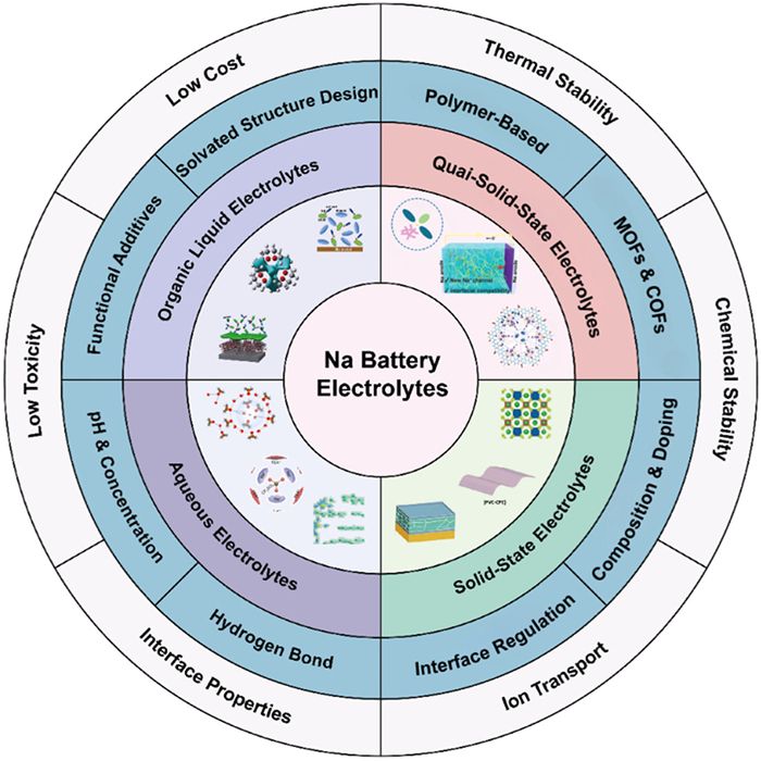
 DownLoad:
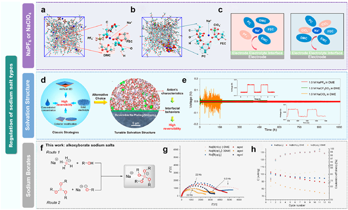
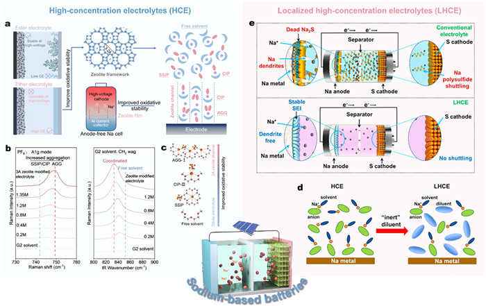
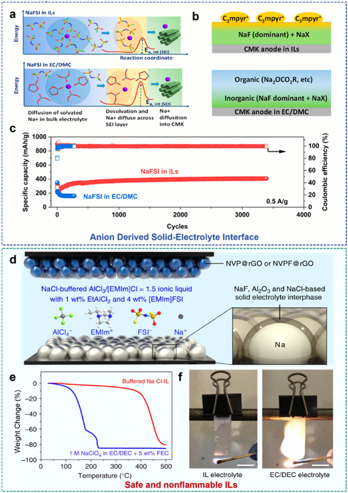
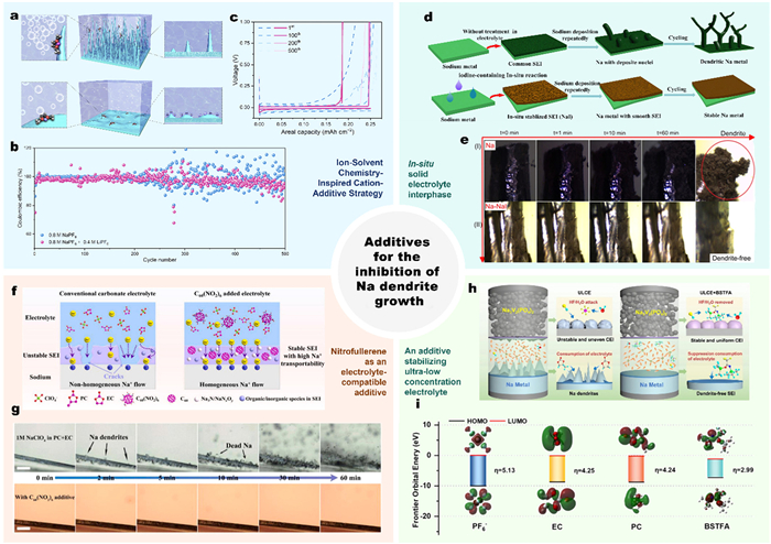

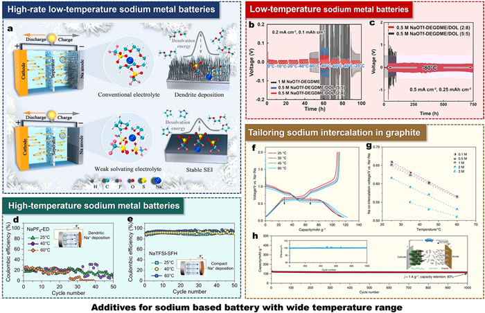
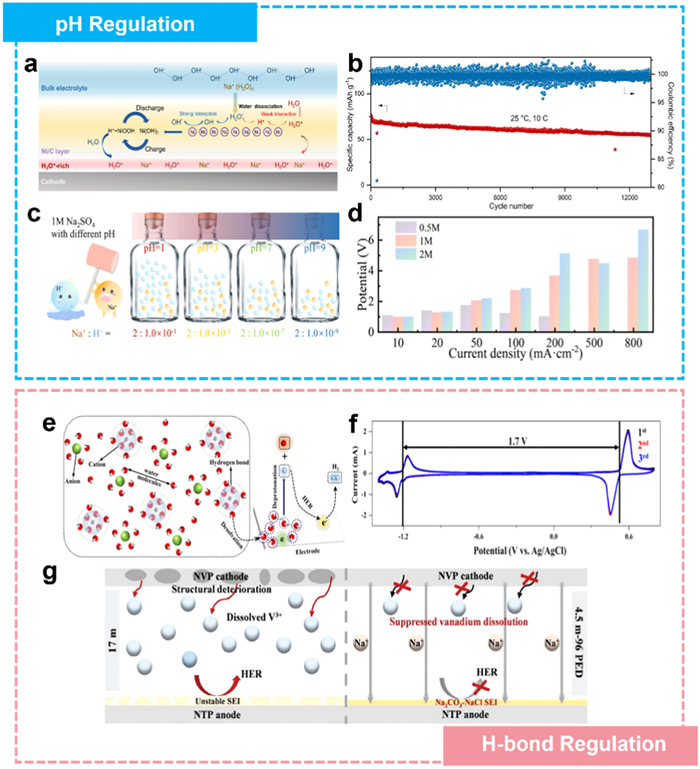
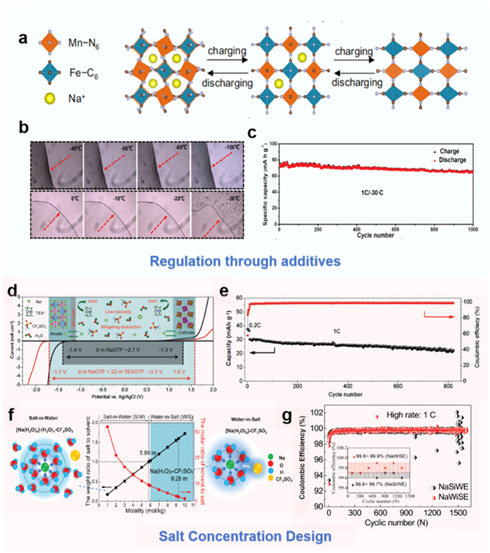
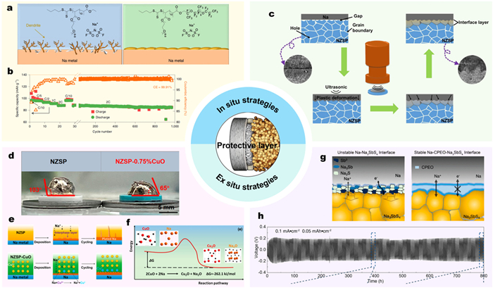
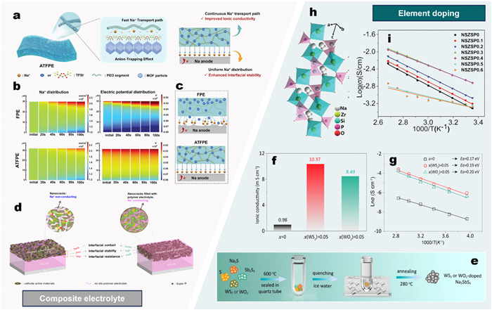
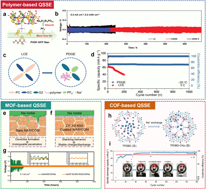

 下载:
下载:


 下载:
下载:

