
Figure 1.
(a) Synthetic route of Ru-NiO/NF. (b) XRD of Ru-NiO/NF. (c) SEM images of NiO/NF. (d) SEM images of Ru-NiO/NF. (e) TEM of Ru-NiO/NF. (f) EDS of Ru-NiO/NF.

Hydrogen is an efficient and clean intermittent energy source, recognized as the most promising energy carrier due to its abundant feedstock, low cost and environmental compatibility [1,2]. Up to now, hydrogen energy has been widely used in different fields, such as new energy vehicles, airplanes, and ships [3]. Therefore, how to produce hydrogen efficiently is increasingly becoming a hot issue for researchers, among which hydrogen production by electrolysis of water has also been explored as an important initiative [4,5]. In the process of water electrolysis, two electrons need to be transferred from hydrogen evolution reaction (HER) to complete the conversion from H+ to H2, and the reaction process needs to overcome the corresponding reaction energy barriers, while the overpotential caused by polarization further amplifies the decomposition voltage [6,7]. Efficient reduction of energy barriers in the water splitting process can be achieved by precious metal catalysts such as Pt and Ru [8,9]. Since precious metals are expensive and scarce on earth, it is imperative to develop efficient catalysts that are low-cost, corrosion-resistant, resource-rich, and pollution-free [10,11].
For optimal electrocatalysts, decreased energy barriers and increased active sites are the ideal conditions to facilitate the HER [12,13]. Although significant advancements have been made in unprecious catalysts, ruthenium (Ru)-related catalytic materials are still recognized as the most active HER catalysts because of their optimum ability to bond with hydrogen [14,15]. The shortcomings of high cost and scarcity have hindered its large-scale application in hydrogen production in electrolyzer. Nevertheless, in alkaline hydrolysis-catalyzed reactions, the splitting of water molecules to produce *H requires a large amount of energy. The participation of Ru promotes the breaking of the O-H bond and accelerates the reaction process [10,16].
Currently, the transition metals-based material is widely used in the field as an effective electrocatalyst, designed to replace the high-cost Ru-modified HER catalysts [17–21]. In order to obtain efficient catalytic activity while saving cost, a number of strategies have been employed to modulate catalyst activity, among which heteroatom doping is considered to be an effective modulation strategy [22,23]. Noble metal atoms modulate transition metal catalysts in doped form with efficient catalytic activity [24,25]. A new Ru-doped hierarchical flower-like Ni2P/NiO heterostructure nanosheet vertically aligned on Ni foam substrate (Ru-Ni2P/NiO/NF HNSs) electrocatalysts was discovered by Zhang et al. The catalyst exhibited high HER activity under alkaline conditions [26]. Zhang and his members have proposed to integrate reactive components of oxygen-evolution reaction (OER) and HER into novel inter-doped ruthenium-nickel oxide [(Ru-Ni)Ox] heterostructures using a self-templated strategy [27]. Luo et al. discussed that the inherent activity of Ru is similar to that of Pt in terms of hydrogen bonds strength and offers the advantages of relatively low cost (Pt cost is about 4%) and excellent endurance, which makes it an ideal alternative to Pt in the HER [28]. In summary, the performances of single transitional metal-based oxide catalysts can be regulated by rational introduction of Ru atomic doping, and excellent HER catalysis can be achieved under alkaline environment.
In this paper, a simple and convenient method of rapid electrochemical synthesis is proposed to design efficient HER catalysts from the problems of low cost and high activity. The Ru-modified NiO/NF was constructed in situ by introducing the noble metal Ru into NiO crystals through a one-step electrodeposition process of in situ formation of NiO phase on the nickel foam surface. Among them, the Ru-modified NiO/NF electrocatalyst was formed due to its unique structure and also significantly reduced the H*-OH adsorption energy, which in turn exhibited significant kinetic promotion and excellent stability. At the same time, it was found that the introduction of Ru atoms further refined the nanoparticles to a specific structure, which greatly increased the specific surface area, thus providing more active sites required for the reaction and achieving an increase in catalytic activity. The catalyst requires only 60 mV overpotential to achieve a current density of 10 mA/cm2 in a 1 mol/L KOH electrolyte, and exhibits an exceptionally long time stability of 115 h, accompanied by an impressive 26.19 mV/dec tafel slope. Because of this, compared to the catalytic activity of NiO/NF, Ru not only increased the active site of NiO/NF, but also enhanced its intrinsic activity, resulting in a 177 mV decrease in its HER activity. DFT calculations also indicate that doping of NiO crystals by introducing a small amount of Ru atoms significantly reduces the Gibbs free energies of *H-OH and *H of NiO in the HER process, confirming that the introduction of metallic Ru can greatly accelerate the HER dynamics at a lower energy barrier. This paper explores the in-situ growth of Ru-NiO/NF, which offers the prospect of a more facile approach to obtaining efficient and stable electrocatalysts.
The one-step electrodeposition method was used, and the Ru atoms successfully replaced some of the Ni atoms in the NiO crystals, which resulted in the in-situ growth of Ru-modulated NiO/NF (Ru-NiO/NF) nanoparticles on NF, and the synthesis process is shown in Fig. 1a. To further characterize the crystalline phase and composition of the catalysts, the prepared materials were analyzed by XRD. The XRD images of Ru-NiO/NF are shown in Fig. 1b, and the diffraction peaks are located at 37.33°, 43.38°, and 63.02° of the (111), (200), and (220) crystal planes of NiO (JCPDS No. 73-1519), respectively. In addition, the diffraction peaks at 44.37°, 51.59°, and 76.08° respectively correspond to the (111), (200), and (220) crystal planes of Ni (JCPDS No. 01-1258). It shows that the material's phase is mainly composed of NiO and Ni.The diffraction peaks of Ru were not detected in the plots, probably due to its poor crystallinity and the effect of an overly strong signal from the Ni foam substrate. The emergence of characteristic derivative peaks associated with metal Ru is not explicitly observed in Fig. 1b. It is observed that the XRD peak positions are generally shifted leftward from the above standard peak positions, which is mainly attributed to the fact that Ru has a larger atomic radius than that of Ni, so that doping induces the peaks to be shifted to the left. Further comparisons were made listing the XRD of NiO/NF modified by different non-precious and non-metallic elements (Fig. S1a in Supporting information), Cr-NiO/NF, V-NiO/NF, S-NiO/NF, and P-NiO/NF all have only three obvious nickel peaks compared to Ru-NiO/NF. This is mainly due to the different chemical properties of different atoms, which subsequently affect NiO/NF differently, resulting in different shifts of the diffraction peaks. Furthermore, the XRD spectrum corresponding to Ru-doped and undoped electrocatalysts was also measured. As shown in Fig. S1b (Supporting information), the diffraction peaks of Ni (200) are shifted to a lower angle after doping, which is due to the fact that the doping radius of Ru is slightly larger than that of Ni2+, resulting in lattice expansion. The shifted positions of the corresponding XRD peaks of the electrocatalysts before and after doping and the change in the intensity of the peaks after doping are side evidence of the successful implementation of metal doping.
As shown in Fig. 1c, the SEM image of NiO/NF confirms that the morphology of NiO/NF is granular and these particles of different sizes are tightly adhered to the surface of NF. The morphology of Ru-NiO/NF, on the other hand, is a kind of three-dimensional loosely packed nanoparticles (Fig. 1d), and compared with the particles of NiO/NF, the morphology of Ru-NiO/NF appears to be more finely and three-dimensionally under the same magnification lens. The particle size is also obviously refined and dispersed. This illustrates that with the introduction of Ru atom doping, the increased specific surface area can provide more active sites required for the reaction. In addition, we have measured the cross-sectional area of Ru-NiO/NF, which has a thickness of about 1.5 µm. In Fig. 1e, the TEM characterization of Ru-NiO/NF is shown, from which it can be found that the lattice stripe spacing of 0.205 nm and 0.237 nm can be attributed to the (111) face of Ni and the (111) face of NiO, respectively. Then, the elemental distribution of Ru-NiO/NF was characterized, as shown in Fig. 1f for its EDS profile, which shows that Ni, O, as well as Ru are all present and uniformly distributed in Ru-NiO/NF. The corresponding data (Fig. S2b in Supporting information) also shows the content of each element and its spectrum, and it was found that the content of Ru is relatively low (only 5.74% atomic percentage of Ru), which also suggests that Ru is present in doped form.
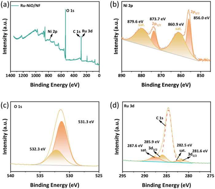
To investigate both the composition of Ru-NiO/NF and its surface chemical valence states, the catalyst was analyzed by X-ray photoelectron spectroscopy (XPS). The XPS full-spectrum scan of Ru-NiO/NF is shown in Fig. 2a to further verify the presence of Ru, Ni, and O elements. In Fig. 2b, a total of four peaks were fitted to the spectrum about Ni 2p, in which the fitted peaks with binding energies at 856.0 and 873.7 eV were attributed to Ni 2p3/2 and 2p1/2, respectively [29], and which were derived from NiO [30,31]. In addition, the binding energy fitting peaks at 860.9 and 879.6 eV were attributed to the satellite peaks corresponding to NiO [32]. Fig. 2c presents the O 1s spectrum of the sample deconvolved into 2 characteristic peaks, which proves the fact that the oxidized state of nickel [33]. As shown in Fig. 2d, the binding energy of the convolution at both 281.6 and 285.9 eV can be attributed to Ru 3d5/2 and Ru 3d3/2, which results correspond to Ru-O bonds. In addition, the fitted peaks at 282.5 and 287.6 eV are the satellite peaks corresponding to Ru 3d5/2 and Ru 3d3/2, whereas the rest of the peaks are attributed to the C 1s [34], and the rest of the peaks are attributed to the C 1s, and this result also suggests that, the Ru in the catalysts in the catalyst is in the oxidized state.
A traditional three-electrode system in 1 mol/L KOH solution was used for HER activity testing of Ru-NiO/Ni together with its corresponding comparison samples. Different atoms have different effects on NiO/NF, either promoting or inhibiting, and Cr, V, P, and S were introduced to modify NiO/NF in addition to Ru. The electrocatalytic performance of Ru-NiO/NF at 10 mA/cm2 all exhibited relatively low overpotentials compared to Cr-NiO/NF (268 mV), V-NiO/NF (187 mV), S-NiO/NF (188 mV), P-NiO/NF (154 mV), NiO/NF (237 mV) and NF (250 mV) (Fig. 3a). In contrast, the Ru-NiO/NF catalyst required only 60 mV overpotential to achieve a current density of 10 mA/cm2, which was second only to Pt/C (42 mV) at the same current density. This suggests that with the introduction of Ru atoms, the electronic structure around NiO/NF was modified, enabling to increase its intrinsic activity, and its morphology was altered to provide more active sites, resulting in a significant improvement of the catalytic activity. Subsequently, the CV curves obtained from our tests were transformed, calculated, and fitted to obtain Fig. 3b with logj as the horizontal coordinate and the Tafel curve corresponding to the activity curve as the vertical coordinate. As depicted in the figure, according to Ru-NiO/NF (26.19 mV/dec) < Pt/C (30.36 mV/dec) < P-NiO/NF (109.24 mV/dec) < NiO/NF (113.10 mV/dec) < S-NiO/NF (121.64 mV/dec) < V-NiO/NF (147.18 mV/dec) < Cr-NiO/NF (167.02 mV/dec) < NF (243.47 mV/dec), with the increase of the current density, the Tafel slopes of Ru-NiO/NF are getting closer and closer to that of Pt/C, even with a tendency to exceed the Pt/C electrode, showing that Ru-NiO/NF possesses an excellent Tafel slope, implying that Ru-NiO/NF has remarkably favorable catalytic kinetics [35,36]. In addition, compared to the catalytic activity of NiO/NF, the Ru not only increases the specific surface area of NiO/NF and thus the number of active sites, but also will decrease its tafel slope leading to enhance the intrinsic activity of NiO/NF to the extent that the HER activity is reduced by 177 mV. Afterwards, in order to probe the kinetic state between the interface of the catalyst surface and the electrolyte both, the electrochemical impedance (EIS) was taken to examine it. Moreover, the above catalysts were compared for HER overpotential and Tafel slope in Fig. 3c, in which Ru-NiO/NF still showed excellent catalytic activity and fast reaction kinetics. As shown in Fig. 3d, the semicircle radii of Cr-NiO/NF, S-NiO/NF, V-NiO/NF, P-NiO/NF, NF, NiO/NF, and Ru-NiO/NF decreased in order, which benefited from the modulation of the electronic structure and morphology of NiO/NF after Ru doping, and exposed more active sites, thus obtaining a more excellent HER activity. The phenomenological scans of Ru-NiO/NF, Cr-NiO/NF, V-NiO/NF, S-NiO/NF, P-NiO/NF, NiO/NF and NF in the non-Faraday region are shown in Figs. S5a-g (Supporting information), respectively. As shown in Figs. 3e and f, at 40–90 mV/s, the Cdl of Ru-NiO/NF (31.4 mF/cm2), Cr–NiO/NF (0.94 mF/cm2), V-NiO/NF (3.37 mF/cm2), S-NiO/NF (1.36 mF/cm2), P-NiO/NF (8.05 mF/cm2), NiO/NF (1.29 mF/cm2), and NF (1.52 mF/cm2) were calculated in this interval based on their corresponding CV curves, respectively. Based on the positive relationship between Cdl and ECSA [37], it can be readily assumed that the Ru-NiO/NF has a better ECSA. The superior ECSA and peculiar particle structure can be assumed to be one of the reasons for the high activity of the Ru-NiO/NF catalyst.
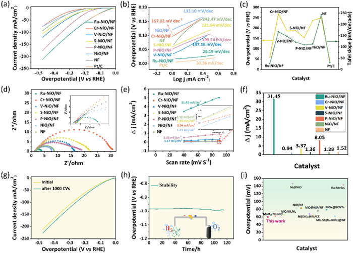
The corrosion resistance of the electrocatalyst is a very important chemical property, as shown in Fig. 3g, after a short period of rapid CV scanning of the catalyst for 1000 cycles, it maintained excellent catalytic activity, and the stability of the catalyst was tested for up to 115 h at a current density of 10 mA/cm2 (Fig. 3h), which fully demonstrated the excellent HER activity and stability of Ru-NiO/NF. Aiming at further investigating the stability profile of Ru-NiO/NF, it was characterized by XRD, XPS and SEM after the HER stability test, respectively. As shown in Fig. S3a (Supporting information), the XRD after stabilization showed almost unchanged physical phase compared with that before stabilization, but the diffraction peaks were shifted to the right. The reason for this is due to prolonged testing, which causes some of the Ru to dissolve into the electrolyte. The characterization results in combination with the morphology of Ru-NiO/Ni (Fig. S3b in Supporting information) show that the morphology is partially agglomerated after stabilization, which indicates that part of the doped Ru is dissolved in the electrolyte during the stability test, which has some influence on the morphology and the position of the diffraction peaks. The XPS after the stability test is shown in Fig. S4 (Supporting information). The elements are consistent with those before the stability test, but the peak intensities of each element are weakened to different degrees after the stability test, which is due to the partial dissolution in the electrolyte during the test. Furthermore, as shown in Fig. 3i (Table S1 in Supporting information), the excellent catalytic effect of Ru-NiO/NF was likewise demonstrated by comparing the overpotential of Ru-NiO/NF at 10 mA/cm2 with that of some HER catalysts in recent years.
To elucidate the mechanism behind the Ru-induced enhancement of HER catalytic activity, density functional theory (DFT) calculations were performed to investigate the effects of Ru on the electronic structure and local ligand environment of NiO. The HER process on the NiO (200) surface was explored via DFT simulations. First, the crystal structures of NiO/NF, Ru-NiO/NF, and the key intermediates, H*-OH and H*, during the HER reaction, were modeled (Fig. 4a). In the process of hydrogen production from electrolytic water, the NiO/NF catalyst completes the hydrogen production reaction path by adsorbing H2O molecules and undergoing the dissociation of H*-OH intermediate state and the formation of H adsorption sites; and after the modification by atomically dispersed Ru doping, the Ru sites in the Ru-NiO/NF catalyst significantly optimize the electronic structure of NiO and lower the water dissociation energy barrier, and at the same time, by enhancing the H adsorption of the active site free energy, the H*-OH dissociation efficiency in the reaction pathway was enhanced, and the synergistic enhancement of hydrogen production rate and catalytic stability was finally realized. Fig. 4a shows that H₂O adsorbs to form *H-OH intermediates, and the process occupies the active site on the NiO surface for a long time, while the energy barrier in b is 0.57 eV, which leads to the reaction path being blocked. Nevertheless, for NiO/NF, the rate-limiting step is the conversion of *H-OH to *H, with a maximum free energy change of 1.05 eV. However, for Ru-NiO/NF, this step is significantly accelerated, and the rate-limiting step shifts to the formation of *H-OH, which requires a reduced free energy change of 0.57 eV. And in Fig. 4b, the energy barrier of NiO curve in the *H stage is significantly higher than that of Ru-NiO, indicating that Ru-NiO/NF can better promote the process of H₂O → *H-OH. Furthermore, the adsorption of OH− as a H₂O dissociation product (H₂O → H-OH → H + OH−) may form stable OH intermediates. And the strongly adsorbed OH− will compete with H for the active site and inhibit the final step of H → H₂ (the NiO curve in Fig. 4b shows a steep rise in the energy barrier at the *H → H₂ stage) On the other hand, the free energy of *H-OH intermediates in unmodified NiO catalysts (0.57 eV) is significantly higher than that of the Ru-NiO system (0.40 eV). This suggests that it is more difficult to desorb with *H-OH on the surface of NiO, leading to more severe toxic effects. These results demonstrate that Ru modification of NiO significantly enhances electronic conductivity, alters surface chemistry, stabilizes reaction intermediates, and lowers energy barriers. In conclusion, Ru modification significantly mitigates such toxicity by modulating the adsorption energy and optimizing the reaction pathway, which provides a key idea for designing efficient HER catalysts. These findings are in excellent agreement with the experimental observations.
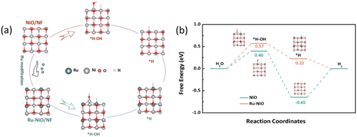
In conclusion, we have successfully developed self-supported Ru-NiO/NF nanoparticles via a rapid electrochemical synthesis method on nickel foam. These nanoparticles exhibit exceptional catalytic activity toward the HER, achieving an overpotential of just 60 mV at 10 mA/cm2 in 1 mol/L KOH electrolyte. The incorporation of Ru into NiO/NF not only increases the number of active sites but also enhances the intrinsic activity of each site, leading to a remarkable 177 mV reduction in HER overpotential compared to pure NiO/NF. The Ru-NiO/NF nanoparticles demonstrate outstanding stability, maintaining HER performance for over 115 h, which is attributed to their three-dimensional architecture that facilitates efficient charge transfer and preserves structural integrity. DFT calculations further showed that Ru doping significantly enhanced the adsorption of *H-OH and the rate-limiting step was converted from *H-OH generation to *H production, and the Gibbs free energy was reduced from 1.05 eV to 0.57 eV, emphasizing its role in improving the catalytic activity and HER kinetics. This work not only provides valuable insights into the role of Ru in NiO-based electrocatalysts but also paves the way for the development of cost-effective, high-performance HER catalysts via a simple and scalable synthesis approach, offering great promise for future energy conversion applications.
The authors declare that they have no known competing financial interests or personal relationships that could have appeared to influence the work reported in this paper.
Li Luo: Writing – review & editing, Writing – original draft, Data curation, Conceptualization. Xiaohong Cheng: Writing – review & editing, Data curation. Qi Wu: Writing – review & editing, Data curation, Conceptualization.
This work is supported by the National Natural Science Foundation of China (No. 22275052) and Department of Science and Technology of Hubei Province (Nos. 2025AFA111 and 2024CSA076). The authors would like to thank Shiyanjia Lab (
Supplementary material associated with this article can be found, in the online version, at doi:
T. Kou, M. Chen, F. Wu, et al., Nat. Commun. 11 (2020) 590. doi: 10.1038/s41467-020-14462-2
T. Zhang, M.Y. Wu, D.Y. Yan, et al., Nano Energy 43 (2018) 103–109. doi: 10.1016/j.nanoen.2017.11.015
J. Quílez-Bermejo, S. García-Dalí, A. Daouli, et al., Adv. Funct. Mater. 33 (2023) 2300405. doi: 10.1002/adfm.202300405
J. Liao, Z. Xue, H. Sun, et al., J. Alloys Compd. 898 (2022) 162991. doi: 10.1016/j.jallcom.2021.162991
S. Battiato, M. Urso, S. Cosentino, et al., Nanomaterials 11 (2021) 3010. doi: 10.3390/nano11113010
S. Xu, X. Yu, X. Liu, C. Teng, Y. Du, Q. Wu, J. Colloid Interf. Sci. 577 (2020) 379–387. doi: 10.1016/j.jcis.2020.05.097
D. Liu, G. Xu, H. Yang, H. Wang, B.Y. Xia, Adv. Funct. Mater. 33 (2023) 2208358. doi: 10.1002/adfm.202208358
M. Sarno, E. Ponticorvo, Appl. Surf. Sci. 459 (2018) 105–113. doi: 10.1016/j.apsusc.2018.07.209
Y. Jia, T.H. Huang, S. Lin, et al., Nano Lett. 22 (2022) 1391–1397. doi: 10.1021/acs.nanolett.1c04840
X. Li, Y. Huang, Z. Chen, et al., Chem. Eng. J. 454 (2023) 140131. doi: 10.1016/j.cej.2022.140131
H. Xie, S. Chen, J. Liang, et al., Adv. Funct. Mater. 31 (2021) 2100883. doi: 10.1002/adfm.202100883
T. Wu, M.M. Melander, K. Honkala, ACS Catal. 12 (2022) 2505–2512. doi: 10.1021/acscatal.1c05820
T. Yu, Q. Xu, L. Luo, C. Liu, S. Yin, Chem. Eng. J. 430 (2022) 133117. doi: 10.1016/j.cej.2021.133117
H. Rajan, S. Anantharaj, J.K. Kim, M.J. Ko, S.C. Yi, J. Mater. Chem. A 11 (2023) 16084–16092. doi: 10.1039/d3ta02390g
X. Guan, Q. Wu, H. Li, et al., Appl. Catal. B: Environ. 323 (2023) 122145. doi: 10.1016/j.apcatb.2022.122145
P. Su, W. Pei, X. Wang, et al., Angew. Chem. 133 (2021) 16180–16186. doi: 10.1002/ange.202103557
R. Koutavarapu, C.V. Reddy, B. Babu, et al., Int. J. Hydrogen Energy 45 (2020) 7716–7740. doi: 10.1016/j.ijhydene.2019.05.163
N. Attarzadeh, D. Das, S.N. Chintalapalle, et al., ACS Appl. Mater. Interfaces 15 (2023) 22036–22050. doi: 10.1021/acsami.3c00781
Q. Wang, X. Cheng, et al., Mater. Adv. 2 (2021) 2104–2111. doi: 10.1039/d1ma00038a
S. Surendran, S.C. Jesudass, G. Janani, et al., Adv. Mater. Technol. 8 (2023) 2200572. doi: 10.1002/admt.202200572
Y. Yan, J. Lin, T. Xu, et al., Adv. Energy Mater. 12 (2022) 2200434. doi: 10.1002/aenm.202200434
D.C. Nguyen, T.L.L. Doan, S. Prabhakaran, et al., Nano Energy 82 (2021) 105750. doi: 10.1016/j.nanoen.2021.105750
H. Su, H. Lou, Z. Zhao, et al., Chem. Eng. J. 430 (2022) 132770. doi: 10.1016/j.cej.2021.132770
P. Bhanja, B. Mohanty, A.K. Patra, et al., ChemCatChem 11 (2019) 583–592. doi: 10.1002/cctc.201801312
J. Zhang, J. Lian, Q. Jiang, G. Wang, Chem. Eng. J. 439 (2022) 135634. doi: 10.1016/j.cej.2022.135634
H. Zhang, X. Wu, C. Chen, et al., Chem. Eng. J. 417 (2021) 128069. doi: 10.1016/j.cej.2020.128069
H. Zhang, Y. Lv, C. Chen, et al., Appl. Catal. B: Environ. 298 (2021) 120611. doi: 10.1016/j.apcatb.2021.120611
W. Luo, Y. Wang, C. Cheng, Mater. Today Phys. 15 (2020) 100274. doi: 10.1016/j.mtphys.2020.100274
A. Mansour, R.A. Brizzolara, Surf. Sci. Spectra 4 (1996) 175–179. doi: 10.1116/1.1247816
T. Xia, J. Liu, S. Wang, et al., ACS Appl. Mater. Interfaces 8 (2016) 10841–10849. doi: 10.1021/acsami.6b01115
A. Mansour, Surf. Sci. Spectra 3 (1994) 231–238. doi: 10.1116/1.1247751
B. Zhang, Y.H. Lui, A.P. Gaur, et al., ACS Appl. Mater. Interfaces 10 (2018) 8739–8748. doi: 10.1021/acsami.8b00069
T.I. Korányi, Z. Vít, D.G. Poduval, et al., J. Catal. 253 (2008) 119–131. doi: 10.1016/j.jcat.2007.10.012
L. An, X. Cai, S. Shen, et al., Dalton Trans. 50 (2021) 5124–5127. doi: 10.1039/d1dt00195g
C. Wang, P. Zhang, J. Lei, W. Dong, J. Wang, Electrochim. Acta 246 (2017) 712–719. doi: 10.1016/j.electacta.2017.06.028
H. Zhou, F. Yu, J. Sun, et al., Proc. Nat. Acad. Sci. U. S. A. 114 (2017) 5607–5611. doi: 10.1073/pnas.1701562114
Y. Zhang, H. Du, Y. Ma, et al., Nano Res. 12 (2019) 919–924. doi: 10.1007/s12274-019-2323-x

Figure 1 (a) Synthetic route of Ru-NiO/NF. (b) XRD of Ru-NiO/NF. (c) SEM images of NiO/NF. (d) SEM images of Ru-NiO/NF. (e) TEM of Ru-NiO/NF. (f) EDS of Ru-NiO/NF.

Figure 3 (a) Polarization curves of Ru-NiO/NF, Cr-NiO/NF, V-NiO/NF, S-NiO/NF, P-NiO/NF, NiO/NF, Ni and Pt/C and (b) their corresponding Tafel plots. (c) Comparison of corresponding catalysts and overpotentials and Tafel Slopes. (d) Nyquist plots. (e, f) Cdl. (g) Comparison of Ru-NiO/NF before and after 1000 turns of CV cycles. (h) Stability tests of Ru-NiO/NF (schematic diagram of hydrogen production by electrolysis of Ru-NiO/NF). (i) Comparison of HER performance of various catalysts with Ru-NiO/NF at 10 mA/dec.

 扫一扫看文章

扫一扫关注我们
 DownLoad:
 下载:
下载:


 下载:
下载: