Figure 1.
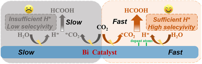
Problems of Bi-based catalyst during CO2RR process and corresponding optimization design.

The conversion of CO2 into valuable chemicals and fuels by electrochemical CO2 reduction reaction (CO2RR) could not only help alleviate the energy crisis but also contribute to establish a carbon-neutral cycle to alleviate greenhouse effect [1–4]. Among various possible products (Table S1 in Supporting information), formate was regarded as an important feedstock for the wide application in medicine, anti-corrosion and other fields [5,6]. Rational designing highly active electrocatalysts for CO2-to-formate is the key to achieve industrial applications [7–10].
Bi-based electrocatalysts have been widely exploited for the reduction of CO2 to formate due to its appropriate energy barrier of OCHO* intermediate [11–14]. Although Bi catalysts have high formate selectivity, there are still challenges to achieve higher productivity [15,16]. This is mainly due to the weak ability to dissociate H2O into protons (H*) of the Bi, resulting in insufficient available H* on Bi, which affects the key step of hydrogenation to form formate intermediates in CO2RR [17,18]. Therefore, promoting the proton supply ability of the Bi-based catalyst is a key point to improve the formate productivity [17,19,20].
It can be expected that providing enough protons at more positively applied potentials can greatly promote CO2-to-formate electrochemically. In fact, many investigations indicated that heteroatom-doping (such as B, C, N, O, S, Cl and so on) in metal/metal oxide could effectively promote the dissociation of water and increase the concentration of protons [21–25]. It has been reported that the introduction of S in Cu2O can obviously promote the conversion of CO2-to-formate. Density functional theory (DFT) calculation results demonstrated that the presence of sulfur could accelerate activation of water for the formation of H* species, and reduce energy barrier for the formation of the key reaction intermediate (OCHO*). Therefore, it is considered to incorporate heteroatoms into Bi catalyst to promote the dissociation of water for proton feeding, so as to improve electrocatalytic performance on the Bi-based catalyst.
In this work, we firstly calculated different heteroatom doping by DFT and predicted the most suitable doping atom (Cl) to increase the concentration of proton for improving the yield of formate. Then, we used electrochemical method to prepare Cl-doped Bi catalyst (Cl-Bi), which had 96.7% formate faraday efficiency (FE) under −0.95 V vs. RHE and 35 h operating stability. The FEHCOOH of Cl-Bi was significantly higher than that of Bi catalyst (89.4%). Meanwhile, Cl-Bi has the highest formate production rate of 275 µmol h−1 cm−2 at −0.95 V vs. RHE, which is 1.2 times higher than that of Bi (224 µmol h−1 cm−2). The combined results of in situ electrochemical characterizations and kinetic studies unveiled that the enhanced CO2-to-formate activity on Cl-Bi could be attributed to the improvement of protons feeding.
As shown in Fig. 1, the catalytic conversion of CO2 to formate on Bi-based catalyst usually includes two steps: First, CO2 and H2O molecules adsorbed on Bi catalyst surface are activated into CO2* and H*, respectively. Then the CO2* combines with H* to form formate. Although the Bi-based catalysts have been proved to have a good activation ability for CO2, the ability to dissociate H2O into H* are weak, resulting in insufficient H* on the Bi surface, so the conversion rate of CO2 to formate are relatively slow [17,26]. Luckily, many studies have demonstrated that nonmetallic doping can effectively improve the ability of H2O dissociation into H* [27,28]. Therefore, we design and propose doping nonmetallic heteroatoms in Bi catalyst to promote H2O dissociation into H*, so that the CO2* and sufficient H* can be quickly combined to form formate.
To explore the effect of different non-metallic elements (including B, C, N, O, F, P, S, and Cl) on Bi metal during electrochemical CO2RR process, density functional theory (DFT) computations were initially performed (Fig. 2). For heteroatom doping, two different doping sites on Bi (012) surface was considered, as show in Fig. 2a. Calculated formation energy of non-metallic elements doped at different sites was shown in Fig. 2b, it can be found that all non-metallic elements tend to replace the outermost Bi atom (site 1) compared with subsurface Bi atom (site 2). Meanwhile, the formation energy of B-doped Bi (B-Bi), C-Bi, and N-Bi greater than 0 eV, indicating their poor thermodynamic stability. In contrary, the formation energy lower than 0 eV of O-Bi, F-Bi, P-Bi, S-Bi, and Cl-Bi indicates the thermodynamically feasible for the doping process.
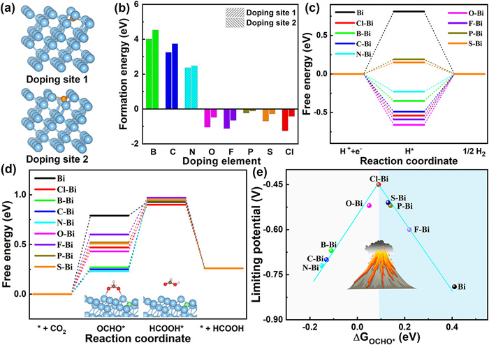
Then, the catalytic activity of different catalysts towards hydrogen evolution reaction (HER) and CO2RR (from CO2 to HCOOH) was evaluated by calculating reaction free energy (Figs. 2c and d). The specific value was shown in Table S2 (Supporting information). A lower activity was observed for pristine Bi owing to its weaker adsorption strength for intermediates. After the doping of non-metallic elements, the adsorption performance of Bi is significantly improved. Take the adsorption free energy of H* (ΔGH*) as an example, an obvious enhancement from 0.81 eV on Bi to −0.66 eV on O-Bi was observed. It is worth mentioning that the ΔGH* of S-Bi (0.15 eV) and P-Bi (0.19 eV) is relatively close to 0 eV, indicating their higher HER activity. The corresponding limiting potentials (the minimum potential to overcome the potential-determined step) of S-Bi and P-Bi is −0.51 and −0.52 eV, respectively. As a result, these two catalysts are not suitable for CO2RR. More important, the volcano curve between the limiting potentials of CO2RR and the adsorption free energy of OCHO* was established (Fig. 2e), where the Cl-Bi exactly stand near the top of the volcano, indicating its optimal CO2RR activity. For comparison, the limiting potential of CO2RR and HER on Cl-Bi is −0.45 and −0.54 eV, respectively, indicating a high selectivity of Cl-Bi during CO2RR process. As mentioned above, Cl-Bi was suggested as most efficient CO2RR catalyst with outstanding stability, excellent intrinsic activity, and high selectivity.
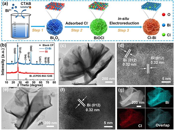
The preparation process of the Cl-Bi catalysts was schematically shown in Fig. 3a. In a typical process, Bi2O3 was first prepared by sonochemical synthesizing method [29], and then chemically converted to BiOCl. Finally, the Cl-Bi catalysts was synthesized through a facile electrochemical conversion strategy using BiOCl as the precursor (Fig. S1 in Supporting information). Fig. 3b showed the X-ray diffraction (XRD) patterns of Bi and Cl-Bi. As the completion of the electroreduction process, the XRD patterns of Cl-Bi exhibited distinct characteristic peaks of Bi (JCPDS No. 44-1246). Only the peaks of metallic Bi existed, confirming that BiOCl was indeed reduced. Transmission electron microscopy (TEM) and high-resolution TEM (HRTEM) images of Bi (Figs. 3c and d) showed the nanoflower structures and the finger lattices was 0.32 nm, corresponding to the (012) plane of Bi. As shown in Figs. 3e and f, the TEM and HRTEM of Cl-Bi also displayed the nanoflower morphology and the same plane (102) of Bi (0.32 nm). These results indicated that the doping of Cl atoms in Bi had no impact on the fundamental structure of Bi nanoflower, which was consistent with XRD results. To further confirm the successful doping of Cl atoms, high-angle annular dark-field scanning transmission electron microscopy (HAADF-STEM) and element mappings were employed. These images indicated that Cl and Bi elements were evenly distributed throughout the Cl-Bi nanoflower (Fig. 3g). This analysis validated the successful fabrication of Cl-Bi nanoflower.
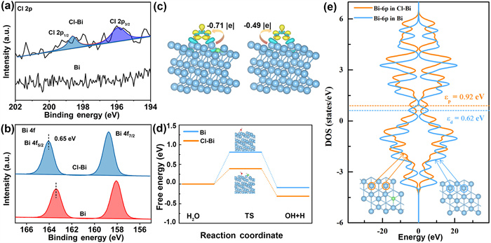
The detailed surface composition and valence state of Cl-Bi were investigated via X-ray photoelectron spectra (XPS). The peaks of Cl 2p2/3 and Cl 2p1/3 located at 197.1 and 199.3 eV were only observed in Cl-Bi (Fig. 4a), implying that Cl was doped successfully [30]. And the amount of Cl doping was detected to be 1.18 wt%. Fig. 4b showed the XPS spectra of Bi 4f. The doublet peaks were corresponding to Bi 4f7/2 (158.1 eV) and Bi 4f5/2 (163.4 eV) [31]. Compared to pure Bi, the doublet peaks were blue-shifted 0.65 eV due to the introduction of Cl atoms. The electron deficient in Bi indicated that the electrons transfer from Bi to Cl occurred due to electronegativity difference. The transfer of electrons also indicated the strong interaction between Cl and Bi, which had a positive effect on the subsequent catalytic reaction. Noting that OCHO* is a key intermediate during CO2RR, the charge density difference of OCHO* on Bi and Cl-Bi was also calculated (Fig. 4c). It can be found that the doping of Cl can significantly promote the charge transfer from Bi to OCHO*, thereby effectively facilitating the first protonation step of CO2. Considering that the main source of H* during the reduction of CO2 is the splitting of H2O, the reaction energy barrier of H2O splitting on Bi and Cl-Bi was further calculated (Fig. 4d). Obviously, Cl-Bi can exhibit a higher catalytic activity on the reaction from H2O to H with a lower energy barrier of 0.39 eV, which suggests that more protons can be generated on Cl-Bi. Accordingly, Cl-Bi can provide H* to the reaction intermediates of CO2RR without delay, thereby accelerating this reaction. To reveal the origin of the enhanced activity caused by Cl-doping, the projected density of states (DOS) of Bi-6p orbital and corresponding p-band centre (εp) on Bi and Cl-Bi were analyzed (Fig. 4e). A significant upward shift of εp (from 0.62 eV to 0.92 eV) was observed after the doping of Cl atom, which means that the introduction of Cl atom can activate the p-band of Bi atoms, subsequently, the catalytic activity can be enhanced substantially [32–34].
The CO2RR activity of Bi and Cl-Bi catalysts was measured in an H-type cell with 0.5 mol/L NaHCO3 solution to elucidate the possible chloride-doped bismuth effect. Linear sweep voltammetry (LSV) curves were measured to evaluate the CO2RR performance in Fig. 5a. The Cl-Bi catalyst showed a much higher current density over the range of −0.85 to −1.05 V vs. RHE than those of Bi, which indicating the enhanced CO2RR reduction on the Cl-Bi catalyst. Fig. 5b exhibited the FEs for different product on Bi and Cl-Bi catalysts at different potentials. The highest value of FEHCOOH was 96.7% at −0.95 V vs. RHE. Meanwhile, Cl-Bi had the highest formate production rate of 355 µmol h−1 cm−2 at −1.0 V vs. RHE (Fig. 5c), which was 1.2 times higher than that of pure Bi (297 µmol h−1 cm−2 at −1.05 V vs. RHE). Notably, CO2RR to formate performance of the Cl-Bi was superior to the reported Bi-based electrocatalysts, which are summarized in Fig. 5d and Table S3 (Supporting information). The electrochemical stability of Cl-Bi catalyst was measured though long-time durability test at −0.95 V vs. RHE (Fig. 5e). The current density and FEHCOOH maintained stable during 35 h operation, demonstrating the excellent stability of the Cl-Bi catalyst. Moreover, the component and morphology were maintained well in Figs. S2 and S3 (Supporting information).
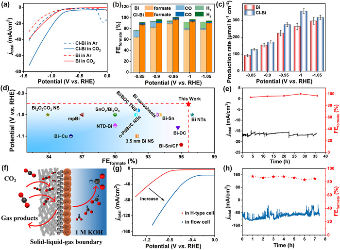
The Cl-Bi catalyst was further used for CO2RR in a flow cell (Fig. 5f) and the diagram of flow-cell was illustrated in Fig. S4 (Supporting information). The current density of Cl-Bi was increased to 100 mA/cm2 at −0.95 V vs. RHE (Fig. 5g) in the flow cell, which was 5.5 times larger than that in H-type cell. As shown in Fig. S5 (Supporting information), the FEformate of Cl-Bi exceeded 80% at −0.7 V to −1.1 V vs. RHE with a CO2 flow rate of 30 sccm (standard-state cubic centimeter per minute). Moreover, the long-term stability test result exhibited that during 7 h operation, the current density had no significant attenuation and FEHCOOH remained stable (Fig. 5h), indicating the good stability of Cl-Bi catalyst. The LSV curves of Cl-Bi catalyst before and after the long-term stability test showed that the two curves nearly coincided (Fig. S6 in Supporting information).
To get insight into the distinct CO2RR performance between Cl-Bi and Bi, in situ ATR-SEIRAS was conducted from −0.6 V to −1.3 V vs. RHE (Figs. 6a-c). The potential-dependent ATR-SEIRAS of Cl-Bi and Bi catalysts for CO2RR was acquired in the range of 600-4000 cm−1 in 0.5 mol/L NaHCO3. Herein, the reduction of intermediates is shown with negative peaks, while the increase in intermediates is shown with positive peaks [35–37]. The peaks were corresponding with absorbed CO2 molecules (2340 cm−1) [38]. As the potentials stepped down from −0.6 to −1.3 vs. RHE, CO2 continually decreased. The peak of 1230 cm−1 in Cl-Bi and Bi catalysts was from O–C–O vibration in OCHO* species, and the intensity on Cl-Bi catalyst was higher than on Bi catalyst [39]. In particular, the negative peak of 1650 and 3420 cm–1 on Cl-Bi was gradually intensified, because of the constant consumption of water during the reaction progressed [40–43]. Water consumption generated abundant H* protons, which were involved in forming intermediates. For Bi catalysts, however, the increase in intensity of this peak was much smaller.
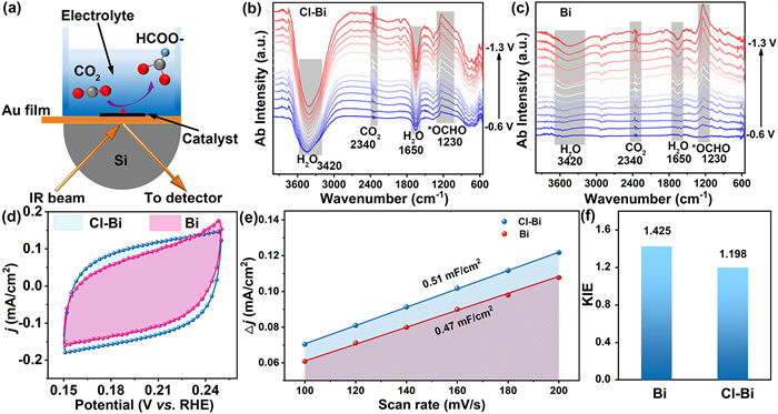
As the accelerated kinetics of the proton supply had been verified, the coverage of adsorption hydrogen (H*) on the catalyst surface could be investigated by electrochemical surface area (ECSA) [40,41]. The ECSA of samples could be intuitive comparison by the non-faraday electrical double-layer capacitance (Fig. 6d). After calculation, the ECSA value of Cl-Bi was 0.51 mF/cm2 (Fig. 6e), which was about 1.1-fold large than that of Bi (0.47 mF/cm2). The results shown that Cl doping could effective regulation the H* coverage on the catalyst surface. Furthermore, after normalized current densities of formate by ECSA, Cl-Bi still exhibted higher activity than Bi (Fig. S7 in Supporting information). To estimate the reaction kinetics of proton transfer rate of the process, the kinetic isotope effect (KIE) of H/D (H2O/D2O) on Cl-Bi and Bi was calculated [35,44,45]. As shown in Fig. 6f and Fig. S8 (Supporting information), Bi exhibited a larger KIE (1.425), implying a slow proton transfer process, which would hinder the CO2 hydrogenation process. In contrast, Cl-Bi possessed a smaller KIE (1.198), manifesting that it promoted protons translocation and OCHO* intermediates formation. Therefore, combining the above results, the improved CO2RR kinetics on Cl-Bi were deciphered. Namely, Cl-Bi catalyst boosted the CO2 adsorption and proton supply, thus, CO2* and H* assembly-line formation of OCHO* intermediates.
In summary, we designed and predicted by DFT calculations that the introduction of Cl atoms on Bi surface could promote a favorable H2O dissociation into H*, thus improve CO2* and sufficient H* quickly combined to improve formate selectivity. And we prepared Cl-Bi catalyst by a facile electrocatalytic reduction method for the electrocatalytic CO2RR to formate. The Cl-Bi catalyst displayed the high FEformate (96.7%) at −0.95 V vs. RHE in an H-type cell, with a current density of 18.8 mA/cm2. The FEformate of Cl-Bi was obviously higher than that of Bi (89.4%). Furthermore, current density reached 100 mA/cm2 and the FEformate was 94.4% at −0.9 V vs. RHE in a flow cell for CO2RR. The work provides a way to design efficient Bi-based electrocatalyst with theoretical prediction guidance, and offers a way to design efficient CO2RR electrocatalyst.
The authors declare that they have no known competing financial interests or personal relationships that could have appeared to influence the work reported in this paper.
Xiao Li: Writing – review & editing, Writing – original draft, Visualization, Validation, Resources, Methodology, Investigation, Formal analysis, Data curation, Conceptualization. Chaoqiong Fang: Writing – review & editing, Visualization, Validation, Software, Methodology, Investigation, Data curation, Conceptualization. Riming Hu: Writing – review & editing, Visualization, Validation, Software, Resources, Methodology, Investigation, Data curation. Jiayuan Yu: Writing – review & editing, Supervision, Resources, Project administration, Investigation, Funding acquisition, Data curation, Conceptualization.
This work was financially supported by the Natural Science Foundation of Shandong Province (No. ZR2022QE076), the National Natural Science Foundation of China (No. 52202092) and the Science and Technology Support Plan for Youth Innovation of Colleges and Universities of Shandong Province of China (No. 2023KJ104).
Supplementary material associated with this article can be found, in the online version, at doi:
P. Sui, C. Xu, M. Zhu, et al., Small 18 (2022) 2105682.
S. Nitopi, E. Bertheussen, S. Scott, et al., Chem. Rev. 119 (2019) 7610-7672. doi: 10.1021/acs.chemrev.8b00705
G. Wang, J. Chen, Y. Ding, et al., Chem. Soc. Rev. 50 (2021) 4993-5061. doi: 10.1039/d0cs00071j
C. Sun, J. Hao, B. Wei, et al., Chin. Chem. Lett. 34 (2023) 108520.
N. Han, P. Ding, L. He, Y. Li, Y. Li, Adv. Energy Mater. 10 (2020) 1902338.
P. Li, F. Yang, J. Li, et al., Adv. Energy Mater. 13 (2023) 2301597.
S. Liu, L. Song, R. Liu, et al., Small 19 (2023) 2304808.
J. Lu, Y. Ren, J. Liang, et al., Small 20 (2024) 2402879.
C. Wang, Z. Lv, X. Feng, W. Yang, B. Wang, Adv. Energy Mater. 14 (2024) 2400160.
H. Sun, J. Liu, Chin. Chem. Lett. 34 (2023) 108018.
S. Yang, M. Jiang, W. Zhang, et al., Adv. Funct. Mater. 33 (2023) 2301984.
P. Deng, H. Wang, R. Qi, et al., ACS Catal. 10 (2020) 743-750. doi: 10.1021/acscatal.9b04043
N. Han, Y. Wang, H. Yang, et al., Nat. Commun. 9 (2018) 1320.
C. Zhang, X. Hao, J. Wang, et al., Angew. Chem. Int. Ed. 63 (2024) e202317628.
Y. Liu, L. Gong, J. Liu, et al., Appl. Catal. B: Environ. Energy 362 (2025) 124760.
Z. Yang, Y. Jin, Z. Feng, et al., ChemSusChem 18 (2025) e202401181.
Y. Liu, Z. Wei, X. Su, et al., Adv. Funct. Mater. 35 (2025) 2403547. doi: 10.1002/adfm.202403547
R. Cui, Q. Yuan, C. Zhang, et al., ACS Catal. 12 (2022) 11294-11300. doi: 10.1021/acscatal.2c03369
S. Liu, M. Gao, S. Wu, et al., Energy Environ. Sci. 16 (2023) 5305-5314. doi: 10.1039/d3ee01999c
P. Lei, S. Liu, Q. Wen, et al., Angew. Chem. Int. Ed. 64 (2025) e202415726.
D. Cha, T. Singh, A. Maibam, et al., Small 19 (2023) 2301405.
B. Yan, X. Qin, T. Chen, et al., Adv. Funct. Mater. 34 (2024) 2309264.
R. Shen, Y. Liu, H. Wen, et al., Small 18 (2022) 2105588.
W. Ma, S. Xie, X. Zhang, et al., Nat. Commun. 10 (2019) 892.
K. Yan, L. Chen, Y. Hu, et al., Nano Res. 17 (2024) 1056-1065. doi: 10.1007/s12274-023-5888-3
Z. Jiang, S. Ren, X. Cao, et al., Angew. Chem. Int. Ed. 63 (2024) e202408412.
A. Fan, C. Qin, R. Zhao, et al., Nano Res. 15 (2022) 6961-6968. doi: 10.1007/s12274-022-4210-0
Q. Guan, W. Ran, D. Zhang, et al., Adv. Sci. 11 (2024) 2401990.
T. Liu, Y. Zhao, L. Gao, J. Ni, Sci. Rep. 5 (2015) 9307.
H. Jiang, S. Huang, H. Lv, et al., Water Res. 225 (2022) 119134.
J. Yang, X. Wang, Y. Qu, et al., Adv. Energy Mater. 10 (2020) 2001709.
X. Wang, M. Zhou, M. Wang, et al., Nano Lett. 2023, 23, 10946-10954. doi: 10.1021/acs.nanolett.3c03173
Y. Meng, M. Wang, J. Xu, et al., Angew. Chem. Int. Ed. 62 (2023) e202308454.
C. Liu, T. Zhang, R. Wang, et al., Adv. Funt. Mater. 35 (2025) 2412144.
E. Corson, R. Kas, R. Kostecki, et al., J. Am. Chem. Soc. 142 (2020) 11750-11762. doi: 10.1021/jacs.0c01953
C. Liu, Y. Wu, K. Sun, et al., Chem 7 (2021) 1297-1307.
Y. Shi, Y. Wang, J. Yu, et al., Adv. Energy Mater. 13 (2023) 2203506.
J. Xue, X. Fu, S. Geng, et al., J. Environ. Manage. 342 (2023) 118354.
X. Cao, Y. Tian, J. Ma, et al., Adv. Mater. 36 (2024) 2309648.
Z. Wei, J. Ding, Z. Wang, et al., Angew. Chem. Int. Ed. 63 (2024) e202402070.
J. Chen, Z. Li, X. Wang, et al., Angew. Chem. Int. Ed. 61 (2022) e202111683.
X. Ren, F. Liu, H. Wu, et al., Angew. Chem. Int. Ed. 63 (2024) e202316640.
J. Li, H. Liu, W. Gou, et al., Energy Environ. Sci. 12 (2019) 2298-2304. doi: 10.1039/c9ee00752k
S. Chen, X. Li, C. Kao, et al., Angew. Chem. Int. Ed. 61 (2022) e202206233.
Z. Guo, H. Zhu, Z. Yan, et al., Appl. Catal. B: Environ. Energy 364 (2025) 124839.

Figure 1 Problems of Bi-based catalyst during CO2RR process and corresponding optimization design.

Figure 2 (a) Schematic diagram of doping sites of non-metallic elements on Bi, the blue and orange spheres represent Bi and non-metallic (including B, C, N, O, F, P, S, and Cl) atoms, respectively. (b) Calculated formation energy of non-metallic elements on different sites. (c) Free energy diagram of HER. (d) Free energy diagram of CO2RR from CO2 to HCOOH. (e) Volcano curve between limiting potential of CO2RR and the adsorption free energy of OCHO*.

Figure 3 (a) Preparation process diagram of Cl-Bi catalyst. (b) XRD patterns of the Bi and Cl-Bi. TEM images of (c) Bi and (e) Cl-Bi. HRTEM images of (d) Bi and (f) Cl-Bi. (g) HAADF-STEM and elemental mappings of Bi (blue) and Cl (red) elements in Cl-Bi catalyst.

Figure 4 High-resolution XPS spectra of (a) Cl 2p and (b) Bi 4f for Bi and Cl-Bi catalysts. (c) Charge density difference map of OCHO on Bi (right) and Cl-Bi (left). The isovalue of the isosurfaces is 3.0 × 10⁻³ eÅ−3, and yellow (cyan) represents the charge accumulation (deletion). (d) Reaction energy barrier of H2O splitting on Bi and Cl-Bi. (e) Density of states of Bi-6p orbital and corresponding p-band center in Bi and Cl-Bi.

Figure 5 (a) LSV curves in 0.5 mol/L NaHCO3 electrolyte for Bi and Cl-Bi. (b) FEs of H2, CO and formate for Bi and Cl-Bi at different potentials. (c) Formate production rate of Bi and Cl-Bi. (d) The comparison of Cl-Bi in CO2RR performances formate-producing catalysts with other reported catalysts using typical H-type cell. (e) Long-term stability and FEHCOOH of Cl-Bi during 35 h. (f) Schematic illustration of flow cell. (g) LSV of Cl-Bi in flow/H-type cell. (h) Operational stability and FEHCOOH of Cl-Bi for 7 h at −0.9 V vs. RHE.

Figure 6 (a) Schematic diagram of in situ ATR-SEIRAS. In situ ATR-SEIRAS spectra of (b) Cl-Bi and (c) Bi at different potentials. (d) Cyclic voltammetry (CV) curves of the Cl-Bi and Bi at 200 mV/s. (e) Calculated ECSA value of Cl-Bi and Bi at various potentials. (f) KIE of Cl and Cl-Bi measured under −0.95 V vs. RHE.

 扫一扫看文章

扫一扫关注我们
 DownLoad:
 下载:
下载:
 下载:
下载: