Analysis and Testing Center, Shandong University of Technology, Zibo 255000, China
b.
School of Agricultural Engineering and Food Science, Shandong Research Center of Engineering & Technology for Clean Energy, Shandong University of Technology, Zibo 255000, China
c.
Tengzhou Fuyuan Low Heat Value Fuel Thermal Power Co., Ltd., Tengzhou 277523, China
d.
Shandong Energy Group Coal Gasification New Material Technology Co., Ltd., Ji'nan 264209, China
Received Date:
16 January 2025 Accepted Date:
27 April 2025 Revised Date:
22 April 2025 Available Online:
15 September 2025
Abstract:
The biomass electrochemical oxidation coupled with hydrogen evolution reaction has received widespread attention due to its carbon-neutral and sustainable properties. The electrosynthesis of 2,5-furanodicarboxylic acid (FDCA) from 5-hydroxymethylfurfural (HMF) oxidation is one of the most promising means for the production of bioplastic monomers. In this work, we constructed a novel P-doped Ni3S2 and Ni heterojunction on nickel foam (P-Ni3S2/Ni/NF) using electrodeposition methods and thermal sulfuration techniques as a bifunctional catalyst for the simultaneous anodic oxidation of HMF to FDCA (HMFOR) and the cathodic hydrogen evolution reaction (HER). On one hand, the synergistic promotion of P doping and the heterojunction of Ni3S2 and Ni accelerated electron transfer, and on the other hand, the structure of three-dimensional microsphere stacking on NF surface to form macropores enhances the exposure of catalytically active sites. The prepared P-Ni3S2/Ni/NF exhibited remarkable performance with high HMF conversion (99.2%), FDCA yield (98.1%), and Faraday efficiency (98.8%), and excellent stability with good product selectivity for 7 consecutive cycles, which stands at a higher level than majority of previously published electrocatalysts. Furthermore, P-Ni3S2/Ni/NF also shows a significant response in HER. By using HMFOR and HER as the anodic reaction and cathodic reaction, respectively, the biomass upgrading and hydrogen production can be carried out simultaneously. The synthesized P-Ni3S2/Ni/NF only need a voltage of 1.31 V to achieve a current density of 10 mA/cm2 in a two-electrode system of HMFOR and HER, which is much lower than that of 1.48 V in OER and HER process, thus potentially reducing the cost of this process.
The expiration of conventional fossil energy sources and increasing environmental pollution have prompted the scientific community to seek other renewable and cleaner alternative sources of energy. Biomass, which is abundant and renewable, can be converted into high value-added organic chemicals and liquid bio-fuels, providing viable solutions to immediate energy crisis and environmental problems [1,2]. Among the various types of biomasses, 5-hydroxymethyfurfural (HMF) derived from cellulose and hemicellulose is a key bridge the biomass and fossil resources, which can be selectively converted into fine chemicals such as 2-formyl-5-furancarboxylic acid (FFCA), 2,5-dimethylfuran (DFF), 5-hydroxymethyl-2-furancarboxylic acid (HMFCA) and 2,5-furandicarboxylic acid (FDCA) [3-6]. Notably, FDCA is an indispensable bio-based alternative precursor for the manufacture of bioplastics with excellent mechanical and thermal properties. This characteristic makes it a promising candidate for developing sustainable and environmentally friendly materials in various industrial applications [7-9]. However, conventional thermocatalytic conversion of HMF to FDCA is carried out predominantly under harsh conditions, along with noble metal oxides as catalyst, which is not only inefficient, but also leads to the secondary waste of resources [10,11]. Electrochemical HMF oxidation (HMFOR) is a clean and environmentally friendly catalytic method in which the oxidized substances (*OH, *OOH, and *O) are derived from the first step of water decomposition without the use of toxic chemical oxidants [12,13]. Moreover, HMFOR has the capability to replace the traditional slow anodic OER coupled with a variety of processes, such as with cathodic hydrogenolysis reaction (HER), nitrogen reduction and carbon dioxide reduction. This integration allows for efficient energy conversion, leading to a substantial enhancement in reaction efficiency [14,15].
There have been significant efforts in investigating Ni-based catalysts for HMFOR under alkaline conditions, with a focus on the production of FDCA, DFF, FFCA, and HMFCA, especially on the improving of the selectivity for FDCA. Such as Ni2P/NF [16], Ni3S2/NF [17], Ni3N/NF [18], and Ni-based heterojunction such as NiCo2O4 [19], Co3O4NiO [20], and NiSx/Ni2P [21] have exhibited excellent HMFOR activity with high conversion efficiency and selectivity. Especially, nickel sulfide has been widely noticed because of its high abundance, low price, and easy preparation method. In addition, nickel sulfide is rich in sulfur vacancies and defects, which can expose additional active sites and optimize the charge transfer pathway, thus improving the reaction efficiency and rate, making it a potential good electrocatalyst for OER [21-24]. Nevertheless, when nickel sulfide is used as catalyst for HMFOR in aqueous media, there is inevitably a competition between HMF oxidation and water oxidation. Therefore, it is great need to further synergistically regulate the electronic structure and surface properties of nickel sulfides electrocatalysts to promote HMF oxidation while suppress water oxidation, this results in efficient hydrogen production and biomass oxidation.
The electrocatalytic properties of nickel-based catalysts are closely related to the electronic environment of the Ni sites. In general, subtle tuning of the electronic structure of Ni-based catalysts can be achieved by modulating the orbital hybridization of the Ni sites, which can be modulated, for example, by changing the type and ratio of ligand bonds in the active site [25,26]. It has been reported that in nickel sulfides, the S2- anions with good electronegativity can reduce the positive electric strength of the electrode surface, thus facilitating the desorption of products as well as the adsorption and desorption of intermediates [27]. In addition, the introduction of heteroatoms (such as N, P, and S) can also optimize the surface properties of electrodes and thus improve the electrochemical performance of the electrodes [28]. Particularly, P doping has been shown to be a good way to improve structural robustness and extend electrode cycle life due to the presence of covalent P-M bonds [29]. And, according to the Lewis acid-base theory, after the formation of P-M coordination, the Lewis acid-base electron pair can effectively improve the activity of the catalyst and decrease the reaction potential [30].
In this work, P doped Ni3S2 and Ni heterojunction on the surface of nickel foam (P-Ni3S2/Ni/NF) was prepared through electrodeposition methods and thermal sulfuration techniques. The P atom doping, the heterojunction interface of Ni3S2 and Ni, and the unique micro-nano structure make P-Ni3S2/Ni/NF with high electronic conductivity, low charge transfer resistance, and high electrochemical surface area, resulting high HMF conversion, FDCA yield and Faraday efficiency (FE) of 99.2%, 98.1% and 98.8%, respectively. More importantly, the synthesized P-Ni3S2/Ni/NF used as bifunctional electrocatalyst to drive the coupled reactions of HMFOR and HER to obtain a current density of 10 mA/cm2 at a low potential of 1.31 V.
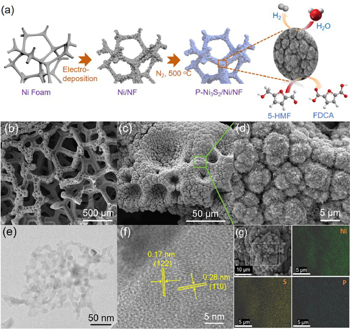
The synthesis schematic of P-Ni3S2/Ni/NF electrocatalyst is shown in Fig. 1a. Firstly, NF coated with Ni microspheres after cathodic electrodeposition method (Ni/NF). Subsequently, the Ni/NF was calcined in N2 atmosphere at 500 ℃ using sublimated sulfur powder as the sulfur source and a small amount of sodium hypophosphite as P doping source, the P-Ni3S2/Ni/NF heterostructure catalyst was yielded finally. The specific morphologies of the obtained samples were clearly characterized by SEM. As shown in Fig. S1 (Supporting information), the Ni3S2/Ni/NF without P doping exhibits micrometer spheres on the NF substrate, which accumulate into macroporous structures. And, the microspheres are aggregates of small micron particles. When P is added and the addition amount of P is 0.5 mmol, P-Ni3S2/Ni/NF is also maintained the microsphere structure and macroporous structure were formed by stacking on the nickel foam surface (Figs. 1b and c). Differently, the particles on the surface of the microspheres are transformed into nanowires after P doping (Fig. 1d). This nanowire structure provides a large contact area for the electrolyte, which promotes the oxidation of HMF. TEM images further revealed the P-Ni3S2/Ni/NF microspheres were composed of nanowires (Fig. 1e). Meanwhile, the clear lattice fringes with planar spacings of 0.17 and 0.21 nm coincide well with the (122) plane of Ni3S2 and (111) plane of Ni, respectively, and there is a clear heterogeneous interface formation in the middle of Ni3S2 and Ni species (Fig. 1f) [31]. The energy dispersive X-ray spectroscopy (EDS) mapping indicates that the uniform distribution of Ni, S, and P elements throughout the whole microspheres. Moreover, the corresponding elemental analysis confirms that the content of Ni, S, and P for P-Ni3S2/Ni/NF is 48.24, 44.68 and 7.08 at% (Fig. S2 in Supporting information). Those further illustrate that the P-Ni3S2/Ni/NF heterostructure are successfully formed.
Figure 1
Figure 1.
(a) Schematic illustration of the synthesis process of P-Ni3S2/Ni/NF electrocatalyst. (b-d) SEM images of P-Ni3S2/Ni/NF with different magnifications. (e) TEM and (f) HRTEM images of P-Ni3S2/Ni/NF. (g) EDX mapping images of P-Ni3S2/Ni/NF.
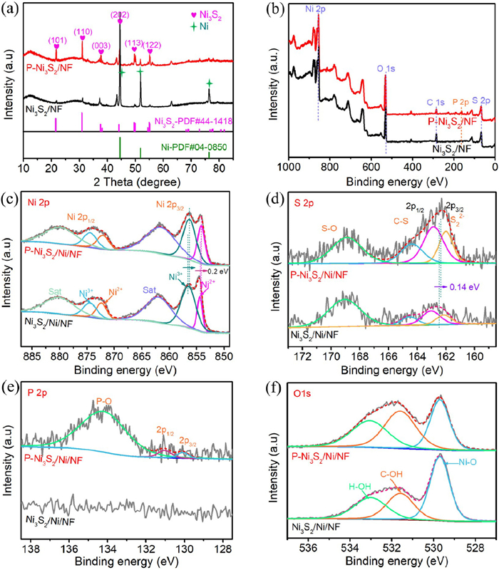
The crystal structures of the prepared catalysts were investigated by XRD. As shown in Fig. 2a, in P-Ni3S2/Ni/NF and Ni3S2/Ni/NF electrocatalysts, the three strong diffraction peaks located at 44.5°, 51.8° and 76.4° can be attributed to the Ni (PDF #04–0850) from NF substrate. And, the peaks at 21.7°, 31.1°, 37.8°, 44.3°, 49.7° and 55.2° corresponds to the (101), (110), (003), (202), (113) and (122) planes of Ni3S2 (PDF #44–1418), which demonstrates the existence of Ni3S2 in P-Ni3S2/Ni/NF and Ni3S2/Ni/NF. The addition of P does not change the crystal structure of Ni3S2/Ni/NF, but shifts slightly to lower angles in different degree, suggesting an increase in lattice distances due to the partial substitution of S atoms by P atoms (Fig. S3 in Supporting information) [29,32].
Figure 2
Figure 2.
(a) XRD patterns of P-Ni3S2/Ni/NF and Ni3S2/Ni/NF. XPS spectra of P-Ni3S2/Ni/NF and Ni3S2/Ni/NF catalyst: (b) Survey spectrum, (c) high-resolution Ni 2p, (d) high-resolution S 2p, (e) high-resolution P 2p, and (f) high-resolution O 1s for P-Ni3S2/Ni/NF and Ni3S2/Ni/NF.
To further identify the surface chemical state of the P-Ni3S2/Ni/NF and Ni3S2/Ni/NF samples, XPS was used for the analysis. The survey spectra of P-Ni3S2/Ni/NF and Ni3S2/Ni/NF are shown in Fig. 2b, indicating the presence of Ni, S, P and O elements on the surface of P-Ni3S2/Ni/NF with no addition impurities, and the presence of Ni, S and O elements on the surface of Ni3S2/Ni/NF. Fig. 2c shows the high-resolution Ni 2p spectrum of P-Ni3S2/Ni/NF and Ni3S2/Ni/NF, which can be assigned to Ni 2p3/2 and Ni 2p1/2. They can be deconvoluted into Ni2+ (853.8 and 871.1 eV) and Ni3+(855.5 and 872.7 eV), with the rest corresponding to the respective satellite peaks [33,34]. Clearly, compared with Ni3S2/Ni/NF, the Ni 2p peaks of P-Ni3S2/Ni/NF after P doping show a slight shift of 0.2 eV toward lower binding energies, respectively, indicating that the P heteroatom doping has an effect on the electronic environment of Ni species [35]. As shown in Fig. 2d, the high-resolution S 2p spectra can be deconvoluted into four peaks at 162.0, 163.3, 164.4, and 168.9 eV, assigning to the S 2p3/2, S 2p1/2 of S22-, C-S, and S-O species [36,37]. The S 2p spectra of P-Ni3S2/Ni/NF also show a negative shift of 0.14 eV compared to Ni3S2/Ni/NF, which is attributed to the strong electronic synergistic effect between P and S, making P-Ni3S2/Ni/NF a highly stable catalyst for electrolysis [29]. The XPS spectrum of the P 2p region in P-Ni3S2/Ni/NF is shown in Fig. 2e, the peaks located at 129.5, 130.4, and 133.4 eV are ascribed to P 2p3/2, P 2p1/2, and P-O species, respectively [38]. Also, As can be seen in Fig. S4 (Supporting information), the P 2p spectra of P-Ni3S2/Ni/NF show a positive shift of 0.16 eV compared to Ni-P/Ni/NF. The high-resolution spectra of O 1s (Fig. 2f) reveal the presence of three forms of oxygen, wherein 530.7, 531.6, and 532.7 eV correspond to typical Ni-O, C—OH, and H—OH adsorbed on surfaces, respectively [39,40]. Based on the analysis of the above physicochemical characterization results, the as-obtained P-Ni3S2/Ni/NF hybrid may provide abundant electroactive sites and the doping of P changes the electronic environment around Ni, which are expected to possess excellent electrocatalytic performance.
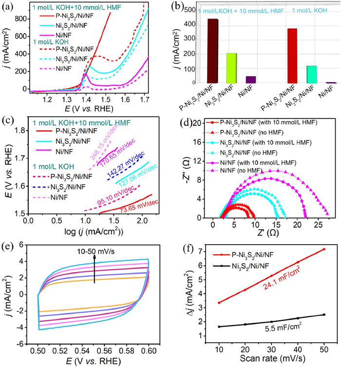
The electrochemical performance of P-Ni3S2/Ni/NF for HMFOR and OER were evaluated in 1.0 mol/L KOH + 10 mmol/L HMF and 1.0 mol/L KOH solution with a typical three-electrode system. As shown in Fig. 3a, after introducing P species, the P-Ni3S2/Ni/NF obtained a current density of 372 mA/cm2 at the potential of 1.45 V vs. RHE in 1.0 mol/L KOH solution, which is much higher than that of Ni3S2/Ni/NF (118 mA/cm2), Ni/NF (19 mA/cm2), indicating the enhanced activity of OER for P-Ni3S2/Ni/NF. When the electrolyte changes from 1.0 mol/L KOH solution to 1.0 mol/L KOH + 10 mmol/L HMF solution, it was observed that the current density increased to 440 mA/cm2 from 372 mA/cm2 for P-Ni3S2/Ni/NF and increased to 204 mA/cm2 from 118 mA/cm2 for Ni3S2/Ni/NF at the potential of 1.45 V vs. RHE, respectively (Figs. 3a and b). In the electrolyte of 1.0 mol/L KOH + 10 mmol/L HMF solution, the HMFOR of P-Ni3S2/Ni/NF had anode current densities of 10 and 100 mA/cm2 at 1.335 and 1.405 V (vs. RHE), respectively. This is attributed to the fact that the reaction energy barrier of HMF oxidation is lower than that of OER, and HMFOR is a thermodynamically more favorable process than OER [41,42], as well as the excellent activities of P-Ni3S2/Ni/NF for HMFOR. The Tafel slope of P-Ni3S2/Ni/NF for HMFOR and OER are determined to be 73.65 and 95.10 mV/dec, respectively, which are much lower than those of Ni3S2/Ni/NF (127.06 and 142.27 mV/dec) and Ni/NF (170.65 and 248.15 mV/dec), indicating a better kinetic profile in HMFOR process for the P-Ni3S2/Ni/NF (Fig. 3c). EIS is applied to further evaluate the HMFOR and OER kinetics of P-Ni3S2/Ni/NF, Ni3S2/Ni/NF and Ni/NF by obtaining the magnitude of the charge transfer resistance (Rct) (Fig. 3d). The obtained P-Ni3S2/Ni/NF displays Rct of 6.4 Ω for HMFOR and 7.7 Ω for OER, which are smaller than those of Ni3S2/Ni/NF (13.3 and 15.1 Ω) and Ni/NF (20.0 and 25.1 Ω), indicating a faster charge transfer rate.
Figure 3
Figure 3.
(a) LSV curves of P-Ni3S2/Ni/NF, Ni3S2/Ni/NF, and Ni/NF at a scan rate of 5 mV/s in 1.0 mol/L KOH with and without 10 mmol/L HMF. (b) Current density at oxidation potential of 1.45 V vs. RHE for P-Ni3S2/Ni/NF, Ni3S2/Ni/NF, and Ni/NF in 1.0 mol/L KOH with and without 10 mmol/L HMF. (c) Tafel plots of P-Ni3S2/Ni/NF, Ni3S2/Ni/NF, and Ni/NF in 1.0 mol/L KOH with and without 10 mmol/L HMF. (d) Nyquist plots of P-Ni3S2/Ni/NF, Ni3S2/Ni/NF, and Ni/NF in 1 mol/L KOH with and without 10 mmol/L HMF. (e) The CV curves of P-Ni3S2/Ni/NF at different scan rate of 10–50 mV/s in 1.0 mol/L KOH with 10 mmol/L HMF solution. (f) The double layer capacitances of P-Ni3S2/Ni/NF and Ni3S2/Ni/NF in 1.0 mol/L KOH with 10 mmol/L HMF.
It is also found that the P specie doping also can affect the ECSA of nickel sulfides which is quantified by the Cdl. The Cdl of P-Ni3S2/Ni/NF and Ni3S2/Ni/NF are obtained through measuring CVs in non-Faradaic current region of 0.5–0.6 V vs. RHE at scan rates of 10–50 mV/s (Fig. 3e and Fig. S5 in Supporting information). As can be seen from Fig. 3f, the P-Ni3S2/Ni/NF has a specific Cdl as high as 24.1 mF/cm2, more than four times of Ni3S2/Ni/NF (5.5 mF/cm2) without P specie doping. In order to determine whether the superior HMFOR activity of P-Ni3S2/Ni/NF originates solely from its higher ECSA, the intrinsic activity was also quantified based on the ECSA-normalized HMFOR current density (Fig. S6 in Supporting information). The P-Ni3S2/Ni/NF still shows a superior intrinsic activity than Ni3S2/Ni/NF, indicating that the P element doping can not only increase the exposed surface area, but also has a profound effect on promoting the reaction kinetics of the catalysts.
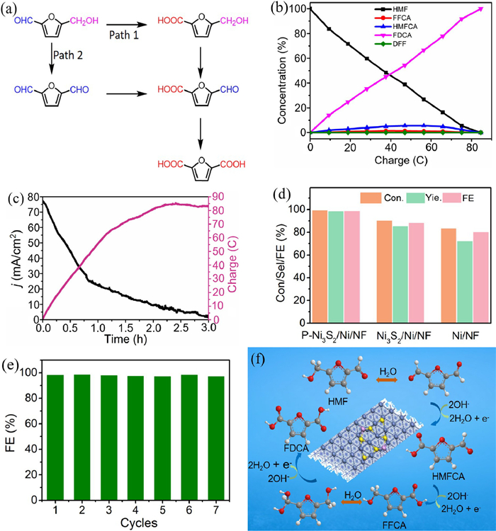
Because of the presence of both hydroxyl and aldehyde groups in the HMF molecule, there are two possible pathways for the HMFOR to ultimately generate FDCA (Fig. 4a). The oxidation of the two groups to form the corresponding intermediates of HMFCA or DFF, and the oxidation of the two intermediates to obtain the same intermediate FFCA, which can be further oxidized to obtain FDCA [43-46]. The HMF electrooxidations were systematically conducted at the potentials of 1.38, 1.40, 1.42, 1.44, 1.46 and 1.48 V. Quantification of concentration changes of HMF molecules, intermediates and final oxidation products were determined using HPLC. The corresponding concentration changes of HMF and its oxidation products during electrocatalytic HMFOR versus the charge passing at each potential were presented in Fig. 4b and Fig. S7 (Supporting information) using the calibration curves (Fig. S8 in Supporting information). The calculated conversions of HMF, selectivity, and FEs of FDCA were plotted in Fig. S9 (Supporting information). The highest conversions of HMF and FEs of FDCA can be achieved at 1.42 V. As the potential rises further (1.44, 1.46, and 1.48 V), the conversion of HMF and FE of FDCA gradually decrease due to the occurrence of the competitive OER. As can be seen from the HPLC spectrum obtained at a voltage of 1.42 V (Fig. S10 in Supporting information), the retention time of FDCA, FFCA, HMFCA, HMF, and DFF was 2.1, 2.6, 3.2, 6.1, and 7.4 min, respectively. The intensity of the peaks of HMF decreases gradually as the charge is increased, while the intensity of the peaks of FDCA increases. Meanwhile, the electrolyte solution containing HMF is initially yellow in color and after electrolysis becomes almost colorless FDCA solution (Fig. S11 in Supporting information). As shown in Fig. 4b, the concentration of HMF and its oxidized products decreased with increasing charge, while the amount of FDCA increased, indicating the successful conversion of HMF to FDCA. Notably, no intermediate product of DFF was detected during the HMF oxidation process except for HMFCA and FFCA, suggesting that the oxidation of HMF using the P-Ni3S2/Ni/NF followed pathway 1, where the aldehyde group of HMF is selectively oxidized to carboxylate groups. Meanwhile, for HMF oxidation into FDCA using P-Ni3S2/Ni/NF electrocatalyst under the condition of 1.42 V, along with the increase of charge, the current density gradually decreases (Fig. 4c). Intriguingly, P-Ni3S2/Ni/NF electrocatalyst exhibits excellent electrocatalytic HMFOR performance at the potential of 1.42 V vs. RHE with high HMF conversion, FDCA yield and FE of 99.2%, 98.1% and 98.8%, respectively, which are much higher than those of Ni3S2/Ni/NF (90.1%, 84.9% and 88.0%) and Ni/NF (83.2%, 71.8% and 80.1%) samples (Fig. 4d), as well as reported non-precious metal catalysts (Table S1 in Supporting information). Moreover, as shown in Fig. 4e, the FE for FDCA is in the range of 97.5%−99.0%, demonstrating that the P-Ni3S2/Ni/NF exhibits superior stability for HMF oxidation. SEM image of the P-Ni3S2/Ni/NF after seven consecutive cycles shows that the microsphere structure and macroporous structure on the NF surface is also maintained (Fig. S12 in Supporting information). XRD pattern of the P-Ni3S2/Ni/NF after seven consecutive cycles shows that Ni3S2 and Ni are still the two main crystalline phases (Fig. S13 in Supporting information). Besides, XPS results were obtained to analyze the state change of the surface. As shown in Figs. S14a-c (Supporting information), the peak of Ni 2p3/2 at about 855.50 eV shows a negligible negative shift of 0.07 eV; however, the proportion Ni3+/Ni2+ decreases from 2.1 to 1.6 due to the oxidation of HMF. The characteristic peaks corresponding to Ni-S and Ni-P still existed after successive electrolysis, while the peak of P-O corresponding to phosphate becomes stronger. In addition, the HMFOR process was investigated using 18O isotope labeling method. The experiment was carried out in 1.0 mol/L KOH + 10 mmol/L HMF and 18O-labeled water (H218O) solution at the overpotential of 1.42 V vs. RHE (Fig. S15 in Supporting information). The mass spectrum of the product has three peaks at m/z of 154.99, 157.00 and 159.01, which correspond to FDCA labeled with all 16O atoms, one 18O atom and two 18O atom, indicating that water not only acts as a solvent, but also as a source of O for HMF oxidation [47]. And, the two main peaks at 139.05 and 141.06 are correspond to FFCA and FFCA with an 18O atom, and the peak at 143.02 represents HMFCA with an 18O atom [48]. Therefore, the mechanism of the HMFOR is shown in Fig. 4f, firstly, H2O molecule entered into the aldehyde group of HMF and then the dehydrogenation reaction took place. Subsequently, HMFCA is converted to FFCA by hydroxymethyl dehydrogenation reaction. Finally, another H2O molecule is added to the aldehyde of FFCA, followed by a dehydrogenation reaction to produce the final product of FDCA with two 18O atoms.
Figure 4
Figure 4.
(a) Two possible pathways for the oxidation of HMF to FDCA. (b) The corresponding concentration changes of HMF and its oxidation products during electrocatalytic HMFOR. (c) Conversion changes of HMF during the HMFOR process. (d) Conversion of HMF, selection of FDCA, and Faradaic efficiency of P-Ni3S2/Ni/NF, Ni3S2/Ni/NF, and Ni/NF samples at 1.42 V vs. RHE. (e) Faradaic efficiency of P-Ni3S2/Ni/NF after seven cycles. (f) Reaction mechanism of HMF oxidation over P-Ni3S2/Ni/NF.
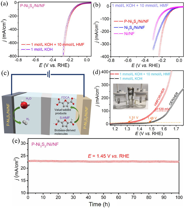
The HER properties of P-Ni3S2/Ni/NF sample is almost the same in 1.0 mol/L KOH and 1.0 mol/L KOH + 10 mmol/L HMF solution, only 150 mV potential is needed to obtain a current density of 100 mA/cm2 (Fig. 5a). And, the P-Ni3S2/Ni/NF electrocatalyst has better HER properties than Ni3S2/Ni/NF (172 mV@100 mA/cm2), Ni/NF (241 mV@100 mA/cm2) in 1.0 mol/L KOH + 10 mmol/L HMF solution (Fig. 5b). Based on the bifunctional catalyst of P-Ni3S2/Ni/NF in HMFOR and HER, a two-electrode system mixing the HMFOR and HER is assembled (Figs. 5c and d insert). As shown in the LSV curves, HMFOR coupled HER electrolysis requires only 1.31 V to achieve the current density of 10 mA/cm2, which is far below than a number of reported non-precious metal catalysts (Table S2 in Supporting information). In contrast, for P-Ni3S2/Ni/NF sample, conventional overall water splitting (OER couple HER) requires a high voltage of 1.48 V to achieve the same current density of 10 mA/cm2. Clearly, to obtain the current density of 100 mA/cm2, the require voltage decreased 120 mV for P-Ni3S2/Ni/NF in 1.0 mol/L KOH + 10 mmol/L HMF solution than in 1.0 mol/L KOH solution (Fig. 5d). Thus, the use of HMFOR as an anodic reaction instead of OER with slow kinetics can be used for the production of high value-added chemicals while reducing the cost of hydrogen production. Exciting, from the chronoamperometry curve of P-Ni3S2/Ni/NF electrocatalyst (Fig. 5e), the current density exhibits a negligible decrease during 100 h continuous test at 1.45 V, showing an excellent stability in the two-eletrode electrolysis in 1.0 mol/L KOH with 10 mmol/L HMF solution. Therefore, we believe that the successfully obtained P-Ni3S2/Ni/NF electrode material is viable for biomass upgrading chemicals and sustainable hydrogen production.
Figure 5
Figure 5.
(a) HER LSV curves of P-Ni3S2/Ni/NF in different electrolytes in 1 mol/L KOH with and without 10 mmol/L HMF. (b) LSV curves of P-Ni3S2/Ni/NF, Ni3S2/Ni/NF, and Ni/NF electrocatalysts in 1 mol/L KOH with 10 mmol/L HMF solution. (c) Schematic diagram of a two-electrode coupled HMFOR and HER electrolysis cell. (d) LSV of P-Ni3S2/Ni/NF in the two-electrode system OER and HMFOR coupled HER. (e) The chronoamperometry measurements (i-t) for P-Ni3S2/Ni/NF in 1 mol/L KOH with 10 mmol/L HMF solution.
In summary, a novel P-Ni3S2 and Ni heterojunction on nickel foam (P-Ni3S2/Ni/NF) was prepared through electrodeposition methods and thermal sulfuration techniques. The proposed P-Ni3S2/Ni/NF acted as a bifunctional electrocatalyst capable of driving the coupling reaction of HMFOR and HER at low potential (1.31 V@10 mA/cm2). And, when P-Ni3S2/Ni/NF is employed as the anode for HMFOR, 99.2% HMF conversion, 98.1% FDCA yield, and 98.8% FE were reached at a low reaction potential of 1.42 V, along with a stable recycling performance for 7 consecutive cycles, which outperforms most of the currently reported catalysts. The P-Ni3S2/Ni/NF heterojunction has high electronic conductivity, low charge transfer resistance, and high electrochemical surface area, all of which are favorable for improving its catalytic performance on catalysts HMFOR. We believe that the constructed P-Ni3S2/Ni/NF heterojunction has great potential for practical applications for the synthesis of FDCA from HMFOR and sustainable hydrogen production.
Declaration of competing interest
The authors declare that they have no known competing financial interests or personal relationships that could have appeared to influence the work reported in this paper.
CRediT authorship contribution statement
Mengzhao Liu: Writing – review & editing, Writing – original draft, Methodology, Investigation, Funding acquisition, Formal analysis, Data curation, Conceptualization. Jie Yin: Methodology, Data curation. Chengjian Wang: Methodology, Conceptualization. Weiji Wang: Methodology, Data curation, Conceptualization. Yuan Gao: Methodology, Conceptualization. Mengxia Yan: Methodology, Formal analysis. Ping Geng: Writing – review & editing, Writing – original draft, Methodology, Investigation, Funding acquisition, Formal analysis, Data curation, Conceptualization.
Acknowledgment
This work was financially supported by Natural Science Foundation of Shandong Province (No. ZR2024QB415).
Supplementary materials
Supplementary material associated with this article can be found, in the online version, at doi:10.1016/j.cclet.2025.111271.
Y.J. Song, Z.H. Li, K. Fan, et al., Appl. Catal. B: Environ. 299 (2021) 120669.
Figure 1
(a) Schematic illustration of the synthesis process of P-Ni3S2/Ni/NF electrocatalyst. (b-d) SEM images of P-Ni3S2/Ni/NF with different magnifications. (e) TEM and (f) HRTEM images of P-Ni3S2/Ni/NF. (g) EDX mapping images of P-Ni3S2/Ni/NF.
Figure 2
(a) XRD patterns of P-Ni3S2/Ni/NF and Ni3S2/Ni/NF. XPS spectra of P-Ni3S2/Ni/NF and Ni3S2/Ni/NF catalyst: (b) Survey spectrum, (c) high-resolution Ni 2p, (d) high-resolution S 2p, (e) high-resolution P 2p, and (f) high-resolution O 1s for P-Ni3S2/Ni/NF and Ni3S2/Ni/NF.
Figure 3
(a) LSV curves of P-Ni3S2/Ni/NF, Ni3S2/Ni/NF, and Ni/NF at a scan rate of 5 mV/s in 1.0 mol/L KOH with and without 10 mmol/L HMF. (b) Current density at oxidation potential of 1.45 V vs. RHE for P-Ni3S2/Ni/NF, Ni3S2/Ni/NF, and Ni/NF in 1.0 mol/L KOH with and without 10 mmol/L HMF. (c) Tafel plots of P-Ni3S2/Ni/NF, Ni3S2/Ni/NF, and Ni/NF in 1.0 mol/L KOH with and without 10 mmol/L HMF. (d) Nyquist plots of P-Ni3S2/Ni/NF, Ni3S2/Ni/NF, and Ni/NF in 1 mol/L KOH with and without 10 mmol/L HMF. (e) The CV curves of P-Ni3S2/Ni/NF at different scan rate of 10–50 mV/s in 1.0 mol/L KOH with 10 mmol/L HMF solution. (f) The double layer capacitances of P-Ni3S2/Ni/NF and Ni3S2/Ni/NF in 1.0 mol/L KOH with 10 mmol/L HMF.
Figure 4
(a) Two possible pathways for the oxidation of HMF to FDCA. (b) The corresponding concentration changes of HMF and its oxidation products during electrocatalytic HMFOR. (c) Conversion changes of HMF during the HMFOR process. (d) Conversion of HMF, selection of FDCA, and Faradaic efficiency of P-Ni3S2/Ni/NF, Ni3S2/Ni/NF, and Ni/NF samples at 1.42 V vs. RHE. (e) Faradaic efficiency of P-Ni3S2/Ni/NF after seven cycles. (f) Reaction mechanism of HMF oxidation over P-Ni3S2/Ni/NF.
Figure 5
(a) HER LSV curves of P-Ni3S2/Ni/NF in different electrolytes in 1 mol/L KOH with and without 10 mmol/L HMF. (b) LSV curves of P-Ni3S2/Ni/NF, Ni3S2/Ni/NF, and Ni/NF electrocatalysts in 1 mol/L KOH with 10 mmol/L HMF solution. (c) Schematic diagram of a two-electrode coupled HMFOR and HER electrolysis cell. (d) LSV of P-Ni3S2/Ni/NF in the two-electrode system OER and HMFOR coupled HER. (e) The chronoamperometry measurements (i-t) for P-Ni3S2/Ni/NF in 1 mol/L KOH with 10 mmol/L HMF solution.

 DownLoad:

 下载:
下载:


 下载:
下载:
