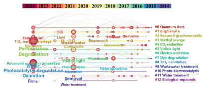
Figure 1.
Citespace of the study on photoelectrocatalytic technology.
Photoelectrocatalytic degradation of refractory organic pollutants in water: Mechanism of active species generation by modulating the photoanode micro-interface
Yuhao Ma , Yufei Zhou , Hongli Li , Cheng Fang , Mingchuan Yu , Shaoxia Yang , Junfeng Niu

Rapid population growth and urbanization have intensified the global shortage of clean freshwater. Organic pollutants from industries, agriculture, and daily activities-such as dyes, phenols, endocrine disruptors, pharmaceuticals, and personal care products-significantly contribute to this issue. Global dye production exceeds 700,000 tons annually, with industries using over 10,000 variants, and around 100 tons are discharged into wastewater yearly [1,2]. Petrochemical wastewater, averaging 0.4–1.6 times the crude oil volume extracted, contains phenolic compounds, which pose severe risks to aquatic ecosystems and biodiversity even at low concentrations [3]. By 2030, global oil demand is projected to reach 107 million barrels per day [4]. Additionally, antibiotics, including macrolides, quinolones, sulfonamides, and cephalosporins, have been detected in Xiong'an, China, with concentrations in surface water, groundwater, and sediments reaching 12.71–260.56 ng/L, ND-196.12 ng/L, and 38.03–406.31 ng/g, respectively [5]. Their environmental persistence fosters antibiotic-resistant bacteria, complicating treatments and causing severe infections. Thus, advanced methods for deep removal of refractory organic pollutants are urgently needed.
Advanced oxidation processes (AOPs), including electrochemical and photocatalytic oxidation, are widely used for water treatment but suffer from high energy consumption and low efficiency. Photoelectrocatalytic (PEC) technology, which combines electrochemical and photocatalytic principles, has gained attention for its low cost, high efficiency, and eco-friendliness. A Web of Science search for "photoelectrocatalysis" and "degradation" yielded 756 articles from January 2014 to October 2024, analyzed using CiteSpace software (Fig. 1), revealing 13 clusters. Among them, "bisphenol A" and "dyes" were the most studied pollutants, and "titanium dioxide nanotubes" and "reduced graphene oxide" were the predominant photocatalytic electrode materials. Recent years have also seen a rise in research on quantum dots for PEC degradation. The growing number of studies indicates that PEC technology is a key method for removing refractory organic pollutants and addressing water pollution.
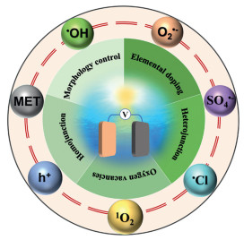
Photoelectrocatalytic degradation requires direct contact between the active photoelectrode surface and pollutants, enabling direct electron transfer for pollutant oxidation–reduction or reactive species generation (e.g., •OH), which drives non-selective mineralization. The efficiency of this process depends on the choice of photoelectrode materials. Unlike electrocatalysis, materials lacking a bandgap cannot generate photogenerated charges, rendering pure metals and graphene unsuitable. Common photoelectrode materials include metal oxides (TiO2, Fe2O3, WO3), metal sulfides (e.g., MoS2), and recently, metal-organic frameworks (MOFs) [6]. Narrow-bandgap semiconductors (e.g., g-C3N4, Ag3PO4) and multi-semiconductor composites are widely used to enhance solar energy utilization [7,8]. For instance, Zhang et al. reported a Ppy-Ag3PO4/BiPO4-coated TiO2 nanotube array with a 92.5% removal efficiency for 100 mg/L PFOA due to enhanced charge separation via n-p-n heterojunctions [9]. Similarly, Zeng et al. developed a 1T-2H MoS2 QDs/Y-NaBi (MoO4)2 multi-heterojunction photoelectrode achieving 99.88% removal of phosphodiesterase-5 inhibitor under visible light, utilizing dual S-type heterojunctions to improve charge separation [10]. The mass transfer rate of photogenerated charge carriers, along with their light absorption, electron transport, and separation properties, are influenced by the micro-interface of the photoelectrode. These properties can be modified through techniques such as morphology control, elemental doping, oxygen vacancies, and heterojunctions and homojunctions (Fig. 2). These modifications enhance the generation of both radicals (e.g., hydroxyl radical (•OH), superoxide radical (O2•-), sulfate radical (SO4•-), chlorine radical (•Cl)) and non-radicals (e.g., singlet oxygen (1O2), mediated electron transfer (MET), photogenerated holes (h+)), which improves the efficiency of photoelectrocatalytic degradation of target pollutants by increasing the yield and altering the types of reactive species produced [11–14]. Existing reviews on photoelectrocatalytic water treatment have summarized methods for modifying photoelectrode materials, degradation performance, and influencing factors [15,16]. In photoelectrocatalytic degradation, the active species produced will be explored, and the different photoelectrode materials and modification methods may play a vital effect on the type and amount of these active species. However, there are few reviews on the active species that can be produced by photoelectrodes and how the regulation of the micro-interface of photoelectrodes affects the production of active species.
Photoelectrocatalytic degradation combines photocatalysis and electrocatalysis to generate a variety of free radicals and non-radical species, effectively degrading refractory organic pollutants. Depending on the added electrolytes and small molecules, reactive species such as •OH, O2•-, SO4•-, and chlorine-based radicals are produced, which non-selectively attack organic compounds. While these radicals are powerful oxidants, they lack selectivity and are susceptible to interference from ions and impurities. Additionally, non-radical species like 1O2, mediated electron transfer, and h+ have been identified in these systems [17,18]. However, comprehensive reviews on the generation of active species and the effects of photoelectrode micro-interface modifications are lacking.
This review provides a comprehensive analysis of recent advancements in the field of photoelectrocatalytic degradation, focusing on the impact of photoelectrode micro-interface modification methods on the generation of active species, as well as how these modification methods have propelled the evolution of photoelectrocatalytic oxidation technology. The review thoroughly discusses the roles of strategies such as morphological control, element doping, surface oxygen vacancies, heterostructure construction, and crystal facet regulation in regulating the activity of micro-interface active species on photoelectrode materials. Moreover, it categorizes and summarizes existing photoelectrode materials based on the types of free radicals and non-radicals generated during the photoelectrocatalytic process. It sheds light on the challenges that persist in effectively removing refractory pollutants from wastewater using photoelectrocatalytic degradation, while also providing practical recommendations.
Organic pollutants in industrial and pharmaceutical wastewater are complex, with significant pH fluctuations, limiting the effectiveness of traditional biological methods [19]. AOPs generate highly oxidative species that non-selectively mineralize refractory organics into CO2 and H2O, achieving detoxification [20]. Common AOPs include ozonation, Fenton oxidation, electrochemical oxidation, and photocatalysis. Photocatalysis employs semiconductor catalysts to harness sunlight energy, producing reactive species for pollutant degradation. As depicted in Fig. S1 (Supporting information), photons with energy (E = hν) ≥ the semiconductor bandgap (Eg) excite electrons (e-) from the valence band (VB) to the conduction band (CB), leaving holes (h+) in the VB. These photogenerated charges drive redox reactions, generating radicals that degrade pollutants into harmless molecules [21]. However, photocatalysis faces e-/h+ recombination, reducing quantum efficiency and catalyst stability due to photocorrosion [22], as well as challenges like light intensity dependency and post-treatment separation of powdered catalysts [23]. Conversely, electrocatalysis produces species like •OH and MOx+1 via anodic redox reactions (Eqs. S1-S8 in Supporting information), effectively oxidizing pollutants [24]. Fixed-electrode electrocatalysts eliminate separation issues and are viable for saline or high-concentration wastewater, though limited by reactive species yield, mass transfer, active site availability, and electrode stability [25]. Combining photocatalysis and electrocatalysis, photoelectrocatalysis synergistically enhances wastewater treatment efficiency.
Photoelectrocatalytic degradation can be divided into electro-assisted photocatalysis and photo-assisted electrocatalysis. In electro-assisted photocatalysis, a steady voltage is applied in the electrolytic cell, while photo-assisted electrocatalysis uses a constant current. The relationship between the two is shown in Fig. S2 (Supporting information).
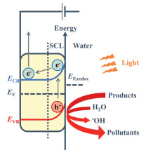
Studies on photoelectrocatalytic degradation of water pollutants predominantly use electro-assisted photocatalysis to explore the degradation mechanisms of anode materials (Fig. 3). When the photoelectrocatalytic material is immersed in water, a Schottky barrier forms due to the difference in Fermi energy levels, creating a space charge layer (SCL) where electrons move inward and holes accumulate at the surface. Upon irradiation, electrons transition from the valence band (VB) to the conduction band (CB), migrating toward the cathode, while photogenerated holes remain at the anode. The application of external bias reduces charge recombination and, when exceeding the flat band potential, enhances band bending and enlarges the SCL. This process depletes electrons and accumulates holes on the semiconductor surface, which promote pollutant adsorption and generate reactive species (•OH) to oxidize organic pollutants.
In photo-assisted electrocatalytic degradation, electrocatalytic oxidation predominates. The pollutant removal efficiency of the photoanode is closely linked to the •OH generation rate, with photo-assisted electrocatalysis outperforming photocatalysis in both removal and •OH production. Studies show that photocatalysis reduces photoelectrode resistance, as indicated by a smaller arc radius in the electrochemical impedance spectroscopy (EIS) spectrum under illumination, suggesting that photogenerated charge carriers enhance electron transfer within the electrode. Moreover, photocatalysis increases active sites on the electrode surface and can oxidize quinone intermediates, clearing blocked sites and activating the electrode [26].
In the process of photoelectrocatalytic degradation of organic pollutants in water, combination of photocatalysis and electrocatalysis exhibits a synergistic effect that enhances the quantum efficiency of light and allowing for the recovery of free heavy metals in water while degrading organic matter. This offers more advantages over simply superimposing the two individual processes. However, it is important to note that the physicochemical properties of the catalyst on the electrode surface are not significantly altered by the photoelectrocatalytic system beyond enhancing the separation efficiency of charge carriers. Thus, the catalytic performance of photoelectrodes plays a crucial role in determining the overall catalytic activity of the system. Since 1972, numerous semiconductor materials have been developed by researchers for use in photoelectrocatalytic systems [27]. For the degradation of refractory organic pollutants in pharmaceutical wastewater, photoanodes must generate highly oxidative h+ to directly oxidize target pollutants or indirectly produce active species with high redox potential (Table S1 in Supporting information). The oxidative ability of h+ is closely linked to the band structure of photoelectrocatalytic materials (Fig. S3 in Supporting information). Common materials for photoelectrocatalytic degradation include TiO2, BiOX (X = Cl, Br, I), WO2, and SrTiO3. While their conduction band oxidation potential exceeds that required for •OH generation, their bandgap generally requires ultraviolet light for electron excitation, and natural sunlight contains only 5% UV light (< 380 nm), limiting light utilization. Additionally, these materials often exhibit high resistance, hindering photogenerated charge transport and leading to high recombination rates, which restricts the efficiency and types of active species generated. Therefore, modification of these materials is necessary for practical applications [28].
In the photoelectrocatalytic degradation of organic pollutants in water, the active components generated on or near the electrode surface play a crucial role. The regulation of the working electrode micro-interface can affect the types and rates of reactive radical components produced during the catalytic process, ultimately influencing the efficiency of photoelectrocatalytic degradation. The following summarizes the impact on active substances stemming from the methods employed for regulating the micro-interface of the photoelectrode.
Recent advancements in water pollutant degradation highlight the necessity of larger specific surface areas in photoelectrodes to facilitate effective interactions with reactants, favoring the use of 2D or 3D configurations. Catalyst morphologies, including nanosheets, nanopores, nanoarrays, nanoflowers, and nanotubes, play crucial roles in enhancing catalytic efficiency [29]. 2D materials, with broad lateral dimensions and thicknesses of 0.1–100 nm, utilize quantum confinement effects to enhance catalytic activity due to electron confinement within limited atomic layers [30]. Meanwhile, 3D nanomaterials offer larger specific surface areas, improving pollutant adsorption, exposing more active sites, and enabling multi-angle light exposure for enhanced absorption efficiency. Morphologies such as nanotubes and nanocones reduce charge carrier migration distances, facilitating photogenerated electron-hole pair separation. Furthermore, nanocones can establish axial electric fields that significantly strengthen charge carrier separation, optimizing photoelectrocatalytic performance [31].
Materials with the same 3D morphology can exhibit different charge carrier separation efficiencies due to their distinct structural configurations, consequently impacting the production of reactive species. Song et al. utilized a hydrothermal method assisted by acetylacetone and sodium acetate (Fig. S4a in Supporting information) to control the growth and formation of TiO2 crystals, thereby creating different morphological structures [31]. Fig. S4b (Supporting information) illustrates that aggregated titanium dioxide particles were synthesized using acetylacetone alone, while a vertical array of nanorods perpendicular to the substrate was synthesized using sodium acetate alone through hydrothermal synthesis, with diameters and lengths of 100 and 450 nm, respectively (Fig. S4c in Supporting information). When both acetylacetone and sodium acetate were added to the hydrothermal reaction, well-oriented titanium dioxide nanocones with a diameter of 50 nm and a length of 1 µm were formed, and these were uniformly and densely distributed on the titanium mesh (Figs. S4d and e in Supporting information) [31].
Based on Mott-Schottky plots, the depletion layer thickness of three TiO2 catalysts was calculated. TiO2 nanocones (NCs) exhibited the thickest depletion layer (343.23 nm) compared to TiO2 nanorods (NRs, 47.66 nm) and TiO2 nanoparticles (NPs, 8.86 nm), indicating the strongest built-in electric field in TiO2 NCs. Correspondingly, photoluminescence (PL) spectra demonstrated a significant reduction in PL peak intensity for TiO2 NCs, suggesting the highest photogenerated charge carrier separation efficiency due to the strong electric field. Furthermore, TiO2 NCs achieved the highest charge injection efficiency into the electrolyte, reflecting an increased proportion of holes transferred from TiO2 NCs to the electrolyte, likely influenced by the distinct catalyst morphologies [32]. Quantitative assessment of •OH concentrations using terephthalic acid (TA) fluorescence indicated the highest TAOH intensity for TiO2 NCs, signifying superior •OH production on its surface. These findings reveal that tailoring the morphology of TiO2 enhances the built-in electric field, significantly improving photogenerated charge separation efficiency and boosting the production of reactive species like •OH.
Element doping introduces extrinsic defects into semiconductor photoelectrodes, creating impurity energy levels within the bandgap. This modification enhances photogenerated charge separation during electron transitions, improving photocatalytic performance. In n-type semiconductors, doped elements typically have more valence electrons than the host material, forming donor levels that facilitate electronic transitions. In p-type semiconductors, doped elements generally possess fewer valence electrons than the host material, creating acceptor levels that capture electrons from the valence band and generate holes (Fig. S5 in Supporting information) [33,34]. Some studies suggest that doping may act as a recombination center for charge carriers, reducing photocatalytic efficiency. Doping elements are typically incorporated during synthesis or by annealing semiconductors in dopant gas atmospheres. The type and concentration of dopants significantly affect catalyst performance. Doping can be classified into metal and non-metal categories, and their introduction into the catalyst lattice expands optical absorption and enhances charge carrier separation.
For non-metal element doping, new localized states are generally introduced above the VB or below the CB of the catalyst, thereby promoting electrical conductivity, light capture, and the separation of e-/h+ pairs, ultimately enhancing the production of active groups and altering the coordination environment at the material surface. Currently, commonly used non-metal elements for doping include nitrogen (N), oxygen (O), sulfur (S), boron (B) and phosphorus (P) [35]. For instance, due to its small ionization energy and comparable size to oxygen atoms, nitrogen is easily doped into the TiO2 lattice, and many nitrogen-doped TiO2 have been used in various photoelectrochemical cells. Doping of interstitial and substitutional nitrogen ions in the TiO2 lattice causes the electronic and band structure of TiO2 to change by introducing localized states at the top of the VB. This modification results in a lowering of the conduction band minimum, leading to enhanced photocatalytic (PC) activity under visible light irradiation [36]. Furthermore, nitrogen doping can effectively induce charge delocalization and regulate the work function of carbon, thereby significantly improving the electron transfer capability of carbon materials [37]. Recent studies have found that nitrogen-doped carbon dots (NCDs) can extend absorption in the visible light region [38]. Therefore, NCDs can be constructed and introduced into semiconductor electrodes to enhance photoelectrocatalytic performance. Sun et al. reported an ordered, porous NCDs-sensitized Bi2O3, exhibiting superior photoelectrochemical and photocatalytic performance than CQDS/Bi2O3 [39]. Similarly, Zhang et al. reduced the bandgap of TiO2 nanotubes by leveraging the electron trapping capabilities of NCDs and oxygen vacancies, promoting the absorption of light energy and generating more •OH, O2•-, and 1O2 [40].
In addition, the incorporation of P element significantly enhances the light absorption and photogenerated charge separation of photoanodes, allowing more efficient utilization of photogenerated charges in the generation of oxidative active species, thereby improving the efficiency of photoelectrocatalytic degradation. Zhang and his team have successfully synthesized P-doped TiO2 nanotube arrays (TNTAs/P) by electrochemical anodic oxidation by precise control of the amount of red phosphorus (Fig. S6a in Supporting information). Optimal doping of TNTAs/P (at a level of 0.75) reaches a remarkable removal of tylosin, reaching 79% after 24 min (λ > 300 nm) [41]. To address the issue of Ti3+ active centers transitioning into higher valence states during the photoanode oxidation process, Liang and colleagues doped P elements by annealing with PH3, designing a nanotube array with a P3+-Ov-Ti3+ coordination (Fig. S6b in Supporting information). Computational analyses indicate that the delocalized electron pairs in the 3s orbital of P3+ significantly alter the valence electron configuration of Ti3+ in the 3d orbital of P3+-Ov-Ti3+, facilitating the formation of intermediate forbidden band states in the bandgap, establishing a new electron transfer pathway. Consequently, Ti3+ exists in a more stable form, exhibiting significant photoelectrocatalytic performance and unprecedented stability in a 1 mol/L NaClO4 electrolyte at 1 mA/cm2, with an expected lifespan exceeding 39,632 h. The main active species generated are •OH and O2•-, and due to P3+ doping, the adsorption of H2O on the photoelectrode is improved, reducing the energy barrier for the generation of •OH, thus enabling the faster production of •OH and other active radicals. In addition to single non-metal element doping, Liu and colleagues explored the co-doping of I and P elements to prepare TiO2 (ITP) catalysts through a hydrolysis method. The synergistic effects of I and P co-doping significantly enhances the separation of photogenerated charge carriers and the visible light absorption capacity of TiO2, ultimately resulting in the production of an abundance of photogenerated holes (Fig. S6c in Supporting information). Some of these h+ directly react with tetracycline (TC), while others are converted to produce •OH to degrade TC. TiO2 with 4 at% P content (IPT-4) exhibits exceptional photoelectrocatalytic performance, achieving the removal of approximately 99.7% of TC from water in 3 h [42].
Metal dopants can modify the electronic structure of semiconductors, creating electron traps to capture photogenerated electrons and suppress charge recombination, or induce lattice defects that enhance reactive species production. However, excessive metal doping may lead to charge recombination, negatively affecting photocatalytic performance [43]. Common metal dopants include noble metals (Pt, Ag, Ru, Ir), transition metals (Fe, Co, Cu, Zn), and others like Sn and In Recent research focuses on using rare earth elements for doping, offering three key benefits: (1) Complex 4f orbitals create impurity energy levels, enhancing charge separation at heterojunctions [44]; (2) upconversion luminescence improves visible light photo-response [45]; (3) lanthanide metals enhance catalytic activity by regulating the semiconductor's crystalline phase [46]. For instance, Nkwachukwu et al. synthesized La-doped perovskite bismuth ferrite (La-BFO) via a low-temperature hydrothermal method [47]. They found that La3+-doped BFO exhibited a higher absorption edge in the visible light range compared to undoped BFO. Notably, the photocurrent response of 10% La-BFO was three times higher than undoped BFO, indicating improved electrode performance due to the synergistic effect of bias potential and La3+ doping.
Additionally, doping with yttrium (Y) has been shown to suppress the transformation of the anatase phase of TiO2 to the rutile phase. By doping Y into the lattice interstices of TiO2 or dispersing it on the surface, bulk or surface defects are created, and these defects can regulate the separation efficiency of electron-hole pairs [48]. NA Narewadikar's team found that doping TiO2 with 1% Y exhibited the highest photoelectrochemical degradation activity. Shifts in the O 1s XPS spectrum reveal the presence of oxygen vacancies in the 1% YTO film due to the bond energy of Y‒O and Ti‒O bonds, affirming that Y3+ doping enhances photocatalytic efficiency [49].
Chen et al. doped the metal Sm into BiVO4 and found that the blue-purple light bands emitted at 447 and 492 nm were excited by near-infrared light at 980 nm, corresponding to the transition decay of the 4G5/2–6H5/2 and 4G5/2–6H7/2 energy levels. Additionally, when doped with the metal Sm, its Rct decreases from 25.91 Ω to 20.47 Ω. This change allows Sm within the photoanode effectively utilize near-infrared light at 980 nm, intensifying light absorption in the 400–500 nm range. Also, it increases the presence of oxygen vacancies in the system, enhancing the carrier lifetime and conductivity of the photoanode. During the photoelectrocatalytic degradation process, the metal Sm acts as a photosensitizer, converting O2 adsorbed on oxygen vacancies into 1O2, thereby increasing the degradation rate of bisphenol A by 36% [50].
Research shows that the release of surface oxygen atoms in semiconductors creates positively charged oxygen vacancies, affecting electron distribution and enhancing photogenerated charge separation [51]. Song et al. noted that oxygen vacancy levels act as electron traps, capturing photogenerated electrons from the valence and conduction bands, preventing charge recombination, and improving photocatalytic activity [52]. Research has found that the release of surface oxygen atoms in semiconductor materials leads to the formation of positively charged oxygen vacancies, influencing the local electron distribution and facilitating the separation of photogenerated charges [53–55]. Song et al. pointed out that the oxygen vacancy level acts as an electron trap, capable of accommodating photogenerated electrons excited from the valence band and returning from the conduction band, which hinders the recombination of photogenerated charge carriers and enhances photocatalytic activity [52]. Introducing oxygen vacancies (OVs) into semiconductors presents a trade-off for charge carrier separation. Excessive OV concentrations may serve as electron-hole recombination centers, reducing carrier separation efficiency. Therefore, carefully tuning the concentration and distribution of OVs is essential to enhance photoelectrocatalytic performance [56,57]. Recently, Cheng et al. successfully synthesized WO3-x thin film photoelectrodes with surface oxygen vacancies using the sol-gel method. Comparing the Raman spectra of WO3 and WO3-x (Fig. S7a in Supporting information), it can be observed that due to the existence of oxygen vacancies, the Raman peak intensity of WO3-x is lower than that of WO3, and the W6+ single bond stretching band at 715 cm-1 shifts to a lower wavelength of 705 cm-1 [58]. Electron spin resonance (ESR) analysis of the samples revealed no ESR signal for WO3 at g ≈ 2.003 was observed (Fig. S7b in Supporting information), however, a symmetrical ESR signal appeared in WO3-x, proving that the surface oxygen vacancies of WO3-x capture electrons. The WO3-x electrode with oxygen vacancies achieved a high deoxynivalenol removal of 86.4% under a low bias of 0.3 V under visible light illumination for 2 h [58].
Electrons trapped in oxygen vacancies readily combine with adsorbed O2, generating reactive oxygen species that enhance photoelectrocatalytic efficiency. For example, Li et al. utilized a Ti mesh with oriented TiO2 nanotube arrays as a photoelectrocatalyst. Electrochemical reduction under a 6 V bias in acidic solution generated H2 microbubbles, causing TiO2 fragmentation and creating oxygen vacancies and Ti3+ defects. These defects promoted •OH production, while oxygen vacancies adsorbed O2 and converted it into O2•- for pollutant degradation. Under visible light at a 6 V bias, 91% of chloramphenicol was removed in 120 min, 9.1 times higher than P25 (10%).
Oxygen vacancies introduce new energy levels slightly below the conduction band within the bandgap, thereby narrowing the forbidden bandwidth for the transition of photogenerated electrons and expanding the spectrum of light utilization [59]. Recent investigations on photoelectrodes by Qin and colleagues revealed that BiMO4 (BMO) with oxygen defects exhibited stronger light absorption in the visible range compared to pristine BiMO4 (BM). BMO demonstrates a redshift of the absorption edge from 481 nm to 514 nm, indicating a reduced bandgap (Figs. S7c and d in Supporting information). The regulatory effect of oxygen vacancies on the bandgap and electrons was further explored through band structure analysis and projected density of states (PDOS), as shown in Figs. S7e and f (Supporting information). The absence of oxygen atoms in BMO produces defect energy levels near the conduction band minimum (CBM) compared to BM [60], facilitating photon-induced electron transitions. Additionally, the PDOS calculations for BM indicate (Figs. S7g and h in Supporting information) that the valence band is contributed by O 2p orbitals, while the excess electrons between Bi atoms and oxygen vacancies are redistributed, promoting the formation of shallow donor energy levels below the CB, thus improving visible light absorption. Consequently, Sg-CN1/BMO5 can degrade 90.2% of chloroquine phosphate within 120 min under low voltage and LED visible light conditions [61]. Furthermore, studies have shown that oxygen vacancies constructed in carbon quantum dots can induce an outward driving force at the BiVO4 and electrolyte interface, thereby promoting hole capture and migration. Compared to using BiVO4 alone or CQDs/BiVO4, the introduction of Ov-CQDs/BiVO4 material leads to a significant increase in photocurrent density by 3.4 times and 2.6 times, respectively [62].
Single semiconductor materials typically exhibit a high rate of photogenerated hole-electron recombination, which limits the efficiency of photoquantum conversion. In photoelectrochemical photoelectrodes, the introduction of new semiconductor/conductor materials to form heterojunctions with the existing photoelectrode materials establishes a built-in electric field at the interface between the two materials, thereby enhancing the separation efficiency of photogenerated charge carriers [63]. An illustration of the band structure facilitating effective carrier transfer in a heterojunction composed of two semiconductors is depicted in Fig. 4a and can be categorized as Type Ⅰ, Type Ⅱ, and Z-Scheme [64]. Type-Ⅰ heterojunction band alignment facilitates carrier transfer between semiconductors due to intrinsic electric field and band bending effects at the interface [65,66]. In contrast, while type-Ⅱ heterojunctions enable the simultaneous transfer of photo-generated electrons and holes between semiconductors, their weakened redox capabilities limit the formation of reactive species such as hydroxyl radicals and superoxide anion radicals. Presently, the exploration of photoelectrocatalytic heterojunctions involving diverse semiconductors predominantly concentrates on constructing Z-Scheme band structures [67,68]. In this band combination, photogenerated electrons with lower reduction potentials and photogenerated holes with lower oxidation potentials undergo recombination at the interface, thus achieving effective separation of photogenerated charge carriers in the two semiconductors [69]. Recent research endeavors, as outlined in Table S2, have often employed Z-Scheme heterojunctions to enhance the activity of photoelectrocatalysts. The combination of distinct heterojunction materials alters the types of free radicals produced, and by constructing heterojunctions with specific substances and photoelectric substrate materials, more selective active components can be generated.
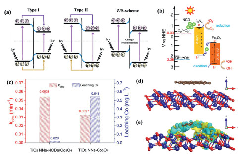
Among various heterojunctions, quantum dots have gained attention as zero-dimensional materials with tunable bandgaps, enhancing charge transfer and storage [70]. For example, carbon quantum dots show promise in improving PEC performance [71]. Dang et al. used nitrogen-doped carbon dots (NCd) to construct an NCd@g-C3N4/Fe2O3 S-scheme heterojunction, achieving 64% methoxyamphetamine degradation in 60 min (Fig. 4b) [72]. Similarly, Hu et al. modified Co3O4 photocathodes with NCDS to reduce recombination and Co3+ evolution. The NCDS/Co3O4 composite achieved significant degradation, with Co leaching reduced from 0.543 mg/L to 0.020 mg/L (Fig. 4c) [73]. The enhanced electron transfer between Co3O4 and NCDS improved degradation efficiency, achieving over 98% sulfadiazine removal in 80 min, with reaction rates 9.78 and 24.45 times higher than electrocatalysis and photocatalysis, respectively (Figs. 4d and e) [73–75].
Similar to heterojunctions, homojunctions are formed using semiconductors with the same chemical composition but different band structures or crystal phases. Semiconductor photoelectrocatalysts from a single precursor with varied crystal forms ensure strong interfacial contact. Unlike heterojunctions, this approach avoids interfacial lattice distortions and bonding discontinuities, reducing charge carrier recombination and improving photoquantum efficiency and active component generation [76].
Studies suggest that photoelectrocatalytic activity can be affected by charge recombination at the particle surface, regardless of phase arrangement. By adjusting crystal form order, charge transfer direction can be controlled to promote efficient separation of photogenerated electron-hole pairs. Thus, rational design of homojunctions in photoelectrodes is crucial. Ma and colleagues sequentially grew monoclinic and hexagonal crystal forms of WO3 on a W wire through a two-step hydrothermal method (Fig. 5a) [77]. Under 1.2 V vs. RHE, the photocurrent density of the hm-m-WO3/W mesh electrode is approximately 5.6 mA/cm2, which is 3.3 times and 9.3 times that of the m-WO3 (1.7 mA/cm2) and h-WO3 (0.6 mA/cm2) electrodes, respectively. Moreover, it achieved complete degradation of bisphenol A and 84.5% mineralization. As shown in Fig. 5b, the superior performance can be attributed to the rational band alignment and formation of a Schottky junction in hm-m-WO3/W. The built-in electric field of the homojunction, aligned with the external bias, promotes efficient migration of photogenerated charge carriers in opposite directions. The network structure also enhances the mass transfer of pollutants to the photoelectrode surface.
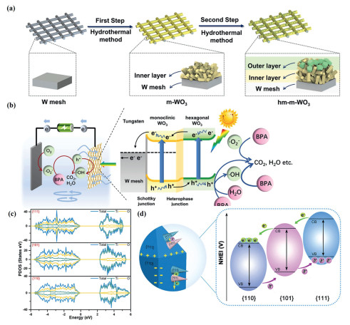
According to some research reports, homojunctions exposing different crystal facets, known as facet heterojunctions, can effectively facilitate the separation of photogenerated charge carriers. Hu and colleagues constructed a three-dimensional multi-level TiO2 homojunction exposing {110}, {101}, and {111} facets [78,79]. Analysis of the PDOS in Fig. 5c reveal that the {111} facet exhibits the highest PDOS intensity near the valence band maximum (VBM), indicating superior electron activity compared to other facets. Furthermore, the PDOS distribution on the CB of the {110} facet is broader, allowing photo-induced electrons to flow in a wider CB. The highest electron density at the bottom of the CB on the {110} facet indicates the accumulation of photogenerated electrons. As illustrated in Fig. 5d, photogenerated h+ and e- accumulate on the {111} and {110} facets, respectively [80]. Ultimately, electrons on the {110} facet migrate along the nanorods to the substrate, achieving more complete separation of photogenerated charges.
Reactive species generated during photoelectrocatalysis are critical for catalytic degradation. These processes can produce both photocatalytic and electrocatalytic reactive species, with the predominant species depending on the photoelectrode materials and small molecule additives (e.g., Cl-, KHSO5, H2O2). The degradation process is primarily classified into radical- and non-radical-type degradation.
•OH is a powerful oxidant (2.8 V) essential for pollutant degradation. In photocatalysis, •OH is generated by the oxidation of water or OH- by photogenerated holes in the valence band. In electrocatalysis, •OH is formed by converting adsorbed water or OH- on the anode surface under external voltage. These oxidation reactions require high activation energies and overpotentials.
Recent research has found that oxygen can be activated to produce reactive oxygen species, yielding H2O2, which is subsequently converted into •OH through a one-electron reduction pathway [81]. However, the steady-state concentration remains low, leading to a relatively sluggish apparent reaction rate [82]. To address this issue, a photoelectrocatalytic approach has been utilized to modulate the electrocatalytic selectivity of the oxygen reduction reaction (ORR). Initially, O2 is reduced to H2O2 as an intermediate, followed by the reduction of H2O2 to •OH by photogenerated electrons in the conduction band. Zhang and his team anchored single-atom Pd on fluorine-doped TiO2 for the rapid generation of •OH through photoelectrochemical reduction of O2, with a selectivity as high as 99% (Fig. S8a in Supporting information) [83]. The formation of a new HO‒O···Pd‒F‒TiO2 chemical bond facilitates the transfer of photogenerated electrons from the conduction band to the single-atom Pd, leading to the reduction of Pd··O‒OH to •OH (Fig. S8b in Supporting information). The optimized •OH production rate reaches 9.18 µmol L-1 min-1, surpassing traditional advanced oxidation processes by a factor of 2.6–52.5 (Fig. S8c in Supporting information) [83].
The Fenton reaction is a key pathway for •OH generation. Recent studies show that Cu-based catalysts outperform Fe-based ones, offering higher reaction rates and better performance under alkaline conditions [84]. However, traditional Fenton reactions often lead to the formation of hydroxide precipitates. Drawing upon prior research findings, Zhang and colleagues anchored single-atom copper on oxygen-vacancy-rich anatase (Cu-SA/TiO2-x) to effectively generate •OH in alkaline solutions. The formation of O‒Cu on the electrode surface promotes the electrocatalytic conversion of H2O2 into •OH (Fig. S8d in Supporting information) [85]. During the photoelectrochemical reduction of O2 at pH 9, the optimal concentration of accumulated •OH was 276.23 µmol/L (Fig. S8e in Supporting information). Using a Cu-SA/TiO2–x electrode with an apparent kinetic constant (kobs) of 0.311 min-1, the removal of sulfamethoxazole reached as high as 96.3% within 10 min (Fig. S8f in Supporting information).
O2•- are primarily produced through semiconductor photocatalysis, where oxygen undergoes reduction into O2•- by photoexcited electrons on the surface of the semiconductor [86], and then these radicals disjoint into the solution to participate in the degradation process of pollutants. Metal oxide photoanode materials are typically capable of generating O2•-. Ma and colleagues fabricated a core-shell structured Ti/Co3O4−MnWO4 photoanode through a two-step hydrothermal method [87]. Due to the conduction band of the composite electrode being at −0.63 V vs. NHE, which has a stronger reducing capability for photogenerated electrons compared to O2, aq/O2•- (−0.16 V vs. NHE) and O2, g/O2•- (−0.33 V vs. NHE), O2 present in both the air and solution is reduced to O2•-. The Ti/Co3O4−MnWO4–5 photoanode demonstrates a remarkable removal of approximately 91.2% for Remazol Brilliant Blue R (KN-R) within 2 h, concurrently achieving an impressive electrode lifetime of 9100 s at a current density of 50 mA/cm2. In another study, Yang and colleagues found that the steady-state concentration of O2•- in the PEC system was significantly higher than that of •OH [87], underscoring the vital role played by O2•- in the degradation of perfluorooctane sulfonic acid.
Additionally, Xie et al. studied the effect of external bias on reactive oxygen species (ROS) generation during photoelectrocatalysis using a TiO2 nanotube (NT) photoanode and Pt cathode [88]. Photogenerated electrons on TiO2 NTs react with O₂ to form O2•-, aiding methyl orange removal. Increasing bias enhances O2•- production, but above 0.2 V vs. SCE, O2•- levels stabilize, indicating equilibrium of electron accumulation on TiO2 NTs. Quenching experiments revealed O2•- dominance in atrazine removal, increasing with anodic bias due to improved electron-hole separation and electron transfer to the cathode. However, hydrogen evolution at the Pt cathode limits this process, causing excess electrons on TiO2 NTs to react with O2. The nucleophilic O2•- reduces atrazine, forming dechlorinated intermediates [89].
Among various reactive radicals, the sulfate radical (SO4•-) has a higher oxidation potential (2.5–3.1 eV) compared to •OH (oxidation potential: 1.8–2.7 eV, half-life: 20 ns) and a longer half-life (30–40 µs), and it can effectively degrade pollutants within a broad pH range (pH 2–8). Therefore, it has attracted widespread attention due to its strong oxidizing power and mineralization efficiency [90]. Peroxymonosulfate (PMS) or peroxydisulfate (PDS) is commonly used to generate SO4•- and •OH [91]. Various semiconductor materials serve as effective activators of peroxysalts, such as transition metal oxides, metal-organic framework nanoparticles, and graphitic carbon nitride. Combining the PEC process with PMS activation for organic pollutant treatments showcases excellent stability and robust oxidizing potential. Dong and his team prepared a hollow structured Pt@CeO2@MoS2 photoanode [92]. Material characterization pre- and post-reaction reveal that PMS molecules react with Ce3+ and Mo4+ on the surface of the photoanode to produce SO4•- (Fig. S8g in Supporting information). Furthermore, Ce4+ and Mo6+ ions participate in the generation of SO5•- radicals. Ultimately, photogenerated electrons reduce Ce4+ and Mo6+. The reaction process for the PMS activation is shown in Eqs. S9-S13 (Supporting information) [92].
MoS2, with its narrow bandgap (1.8 eV), can absorb visible light and provides abundant Mo4+/Mo6+ active sites to facilitate the PMS activation [93]. Additionally, it has been found that the 1T phase (octahedral symmetry) of MoS2 possesses higher electronic conductivity compared to its polycrystalline counterparts, offering more catalytic reaction sites. Zheng and colleagues synthesized a 1T/2H-MoS2@C/CC (carbon cloth) photoanode for the removal of norfloxacin from water [94]. Experimental analyses involving h+ and e- scavengers reveal that e- participate in part in the Mo4+/Mo6+ cycle to activate PMS at the photoanode surface [95]. Simultaneously, a portion of the electrons migrate to the cathode to directly activate PMS, generating •OH. The suppression of h+ quenching enhances the separation of photogenerated electrons, leading to a higher yield of photogenerated electrons and promoting both direct and indirect activation of PMS. Under the synergistic action of photoelectrocatalysis and PMS, the 1T/2H-MoS2@C/CC photoanode completely removed 2 mg/L norfloxacin within 30 min (1.5 V, visible light, 40 mg/L PMS).
In wastewater and natural water bodies, a large amount of chloride ions (Cl-) convert to perchlorate during the electrochemical process [96]. Meanwhile, chloride anions in water may also participate in (photo)electrochemical reactions, generating chlorine-based radicals (such as HOCl/OCl- and •Cl), which affect the degradation rate of pollutants and the subsequent degradation pathways [97]. In the presence of •OH, Cl- in water undergo the following reactions, Eqs. S14-S20 (Supporting information), on the photoanode surface to generate chlorine-based radicals [86].
Zheng et al. fabricated MoS2–3@BiVO4 photoanode materials for the photocatalytic degradation of bisphenol A (BPA) in a solution with NaCl as the electrolyte. Quenching experiments and EPR characterization reveal that •ClO and •Cl serve as the primary reactive species generated on the photoanode surface during the photocatalytic degradation process, completely degrading 10 mg/L of BPA within 75 min under a bias of 1.5 V and visible light irradiation [93]. In a recent study, Zhou investigated the photocatalytic degradation of organic matter in water under high Cl- concentrations using high-NaCl waste liquid from the glyphosate industry. Using TiO2 nanotubes as the photoanode, after PEC deep treatment, the total organic carbon (TOC) of the waste salt was reduced to below 20 mg/L, meeting the requirements of the chlor-alkali industry for refined salt [98]. Studies on the photocatalytic mechanism indicate that •OH can be generated at low Cl- concentrations, while high Cl- concentrations suppress the generation of •OH [98]. Under high Cl- concentration conditions, the main oxidative substances responsible for degradation are holes and chlorine-active species other than •Cl. During the chlor-alkali electrolysis process, organic impurities in the waste salt are toxic to both the electrode and the membrane, leading to increased voltage. Photocatalytic treatment can remove most of the organic impurities, thus allowing the waste salt to be used as a raw material for chlor-alkali electrolysis. EIS analysis shows that when waste salt is used as a raw material for chlor-alkali electrolysis, and the organic impurities in the waste salt are toxic to both the electrode and the membrane, leading to increased voltage and reduced electrolysis efficiency [98]. After photocatalytic treatment, most of the organic impurities are removed, enabling the waste salt to be used for chlor-alkali electrolysis.
Non-free radical species have longer lifetimes than radicals, allowing prolonged interactions with pollutants. They also show greater resistance to environmental interferents, such as inorganic anions and high organic matter concentrations, making them effective for treating complex or high-pollutant waters. Additionally, non-free radical pathways offer higher selectivity, enabling targeted pollutant degradation while minimizing side reactions and energy consumption.
1O2 is a typical non-free radical reactive species, characterized by a relatively long lifetime and strong resistance to interference. 1O2 can be directly produced from peroxides, such as peroxymonosulfate (PMS) and hydrogen peroxide (H2O2), using catalysts that contain metal and carbon, like metal-organic frameworks (MOFs) [99]. Sun et al. designed a PEC system with an S-type MgO/g-C3N4 photoanode and modified carbon fiber felt (MCF) cathode for effective tetracycline degradation. The photoanode activates H2O2 produced by the MCF cathode [7]. Experimental and DFT studies (Fig. S9a in Supporting information) show that Mg-N coordination is key to activating H2O2 to generate 1O2 and •OH. In the PEC activation of PMS, 1O2 generation occurs through PMS self-decomposition, O2•- transformation, and activation by carbon materials [100]. Fig. S9b (Supporting information) suggests that 1O2 is produced via two pathways: the reaction of O2•- with •OH and electron transfer to PMS via carbon cloth [94]. Feng et al. proposed selective regulation of •OH and 1O2 production for removing dimethyl phthalate and atrazine (ATR) using a copper-coordinated carbon nitride electrode (CuCN) [101]. Experimental characterization and DFT calculations (Fig. S9c in Supporting information) show that Cu atoms near N (Cu-N2C) activate oxygen to produce •OH and 1O2. Fig. S9d (Supporting information) shows ATR degradation via GC–MS, where 1O2 reacts with the N adjacent to the alkyl side-chain in ATR, initiating alkyl oxidation. The C–Cl bond of the intermediate can be attacked by 1O2, leading to dechlorination and hydroxylation. Finally, 1O2 attacks the amino group of the intermediate, forming the end product [101].
In mediated electron transfer, electrons are transferred from one adsorbate to another via a catalyst. This occurs in carbon-based photoelectrodes, where electrons move from pollutants to PMS, activating PMS photocatalytically. Despite its importance, mediated electron transfer in photocatalysis is still underexplored. In 2021, Nnamdi et al. prepared a visible-light-responsive TiO2-graphene oxide nanosheets-Zn phthalocyanine (TiO2@GONS@ZnPc) ternary heterojunction photocathode for the photoelectrochemical degradation of orange G azo dye. They demonstrated the non-free radical activation of PMS using the ZnPc-GONS catalyst (Fig. S10a in Supporting information), with GONS and ZnPc mediating charge transfer in PMS activation [102]. Zuo et al. found that positively charged CuO in CuO–CN interacts with anionic PMS, forming reactive complexes that enhance PMS reactivity for diclofenac degradation. DFT calculations suggest that the CuO–CN heterojunction, with its polarized electric field, promotes non-free radical activation by coupling with negatively charged HSO5 (Fig. S10b in Supporting information). CuO–CN outperforms CuO, improving diclofenac degradation by 29 times [103].
Photogenerated holes, as active components generated in situ on the surface of semiconductor material photoanodes, can undergo direct redox reactions with target pollutants adsorbed on the photoanode surface, thus constituting a non-free radical degradation pathway.
Shao et al. introduced PMS into a PEC system with a bismuth vanadate (BiVO4) photoanode to enhance the degradation of bisphenol A (BPA). The degradation efficiency significantly increases from 24.2% to 100.0% with the addition of 5 mmol/L PMS at a low voltage of 0.25 V. Mechanistic investigation results indicate that SO4•- and •OH are not the primary reactive species responsible for BPA degradation. PMS can act as an electron acceptor for photogenerated electrons through a two-electron reduction process (E0 (HSO5-/SO42-) = 1.75 V vs. NHE), facilitating the separation of photogenerated charges on the BiVO4 photoanode and thereby generating more photogenerated holes to enhance BPA degradation (Figs. S11a and b in Supporting information) [104]. Li et al. combined photocatalysis, ozonation, and electrocatalysis using rGO/BiOCl nanocomposite materials as the photoanode. The removal rate of PFOA reaches an unprecedented 95.4% within 3 h, which is superior to the processes of photocatalytic ozonation (80.5%) and photoelectro-Fenton (56.1%). The synergistic effect of the oxidation by photogenerated holes and the accelerated formation of •OH by H2O2 generated at the cathode contributes to the degradation. By identifying the degradation intermediates (Figs. S11c and d in Supporting information), it is found that the decarboxylation of PFOA was initiated by the strong oxidative h+, forming an unstable perfluorooctyl group, which further transformed into short-chain perfluorocarboxylic acids through reaction with •OH [105].
Photoelectrocatalysis, as an efficient and environmentally friendly water treatment technology, has demonstrated significant potential for degrading recalcitrant organic pollutants. By modifying the micro-interface of the photoanode, the generation of active species can be effectively enhanced. The synergistic action of different active species improves the overall efficiency of the photoelectrocatalytic process. Strategies such as morphology control, element doping, surface oxygen vacancy creation, and heterostructure construction have proven to be effective in enhancing the performance of photoelectrocatalysts. These strategies improve organic pollutant degradation by enhancing photogenerated charge separation, increasing active sites, adjusting the band structure, and promoting charge carrier migration. Future research should focus on exploring new photoelectrocatalytic materials and optimizing control strategies to enhance the practical application and economic feasibility of photoelectrocatalysis in environmental management.
The authors declare that they have no known competing financial interests or personal relationships that could have appeared to influence the work reported in this paper.
Yuhao Ma: Writing – original draft. Yufei Zhou: Writing – review & editing. Hongli Li: Writing – review & editing. Cheng Fang: Writing – review & editing. Mingchuan Yu: Writing – original draft. Shaoxia Yang: Writing – review & editing. Junfeng Niu: Supervision.
This study was financially supported by the National Natural Science Foundation of China (No. 52100076) and the Fundamental Research Funds for the Central Universities (No. 2023MS064).
Supplementary material associated with this article can be found, in the online version, at doi:
K. Vikrant, B.S. Giri, N. Raza, et al., Bioresour. Technol. 253 (2018) 355–367. doi: 10.1016/j.biortech.2018.01.029
Q. Liu, IOP Conf. Ser.: Earth Environ. Sci. 514 (2020) 052001. doi: 10.1088/1755-1315/514/5/052001
R. Khan, Z. Haram, W. Ahmad, et al., Sci. Rep. 14 (2024) 17236. doi: 10.1038/s41598-024-66429-8
B. Aslam, J. Hu, S. Ali, T.S. AlGarni, M.A. Abdullah, Int. J. Environ. Sci. Technol. 19 (2022) 3189–3200. doi: 10.1007/s13762-021-03279-1
C. Fu, B. Xu, H. Chen, et al., Sci. Total Environ. 807 (2022) 151011. doi: 10.1016/j.scitotenv.2021.151011
H. Du, W. Ma, J. Qian, et al., J. Environ. Chem. Eng. 12 (2024) 112269. doi: 10.1016/j.jece.2024.112269
J. Sun, H. Wu, C. Fu, et al., Appl. Catal. B 351 (2024) 123976. doi: 10.1016/j.apcatb.2024.123976
W. Shen, B. Wang, L. Wang, et al., Sep. Purif. Technol. 359 (2025) 130516. doi: 10.1016/j.seppur.2024.130516
D. Zhang, Y. Li, X. Chen, et al., Sep. Purif. Technol. 287 (2022) 120521. doi: 10.1016/j.seppur.2022.120521
Q.R. Zeng, Z.A. Jia, X. Liu, B.W. Xiu, J.P. Cheng, Appl. Catal. B 327 (2023) 122460. doi: 10.1016/j.apcatb.2023.122460
Q. Wang, A. Liu, B. Shen, et al., Chem. Eng. J. 502 (2024) 157806. doi: 10.1016/j.cej.2024.157806
H. Deng, Y. Wu, L. Li, et al., Sep. Purif. Technol. 354 (2025) 129455. doi: 10.1016/j.seppur.2024.129455
H. Deng, Y. Hui, C. Zhang, et al., Chin. Chem. Lett. 35 (2024) 109078. doi: 10.1016/j.cclet.2023.109078
M. Deng, J. Guo, X. Ma, et al., Sep. Purif. Technol. 326 (2023) 124786. doi: 10.1016/j.seppur.2023.124786
S. Wu, Y.H. Hu, Chem. Eng. J. 409 (2021) 127739. doi: 10.1016/j.cej.2020.127739
R. Tang, S. Zhou, Z. Zhang, R. Zheng, J. Huang, Adv. Mater. 33 (2021) 2005389. doi: 10.1002/adma.202005389
L. Zhang, R. Djellabi, P. Su, Y. Wang, J. Zhao, J. Environ. Sci. 124 (2023) 300–309. doi: 10.1016/j.jes.2021.08.054
M. Kumar, C.C. Ghosh, B. Meena, T. Ma, C. Subrahmanyam, Sustain. Energy Fuels 6 (2022) 3961–3974. doi: 10.1039/d2se00600f
D. Ma, H. Yi, C. Lai, et al., Chemosphere 275 (2021) 130104. doi: 10.1016/j.chemosphere.2021.130104
Y. Li, H. Dong, L. Li, et al., Water Res. 192 (2021) 116850. doi: 10.1016/j.watres.2021.116850
X. Bai, W. Chen, B. Wang, et al., Int. J. Mol. Sci. 23 (2022) 8130. doi: 10.3390/ijms23158130
Y. Fang, H. Wang, X. Wang, et al., Sep. Purif. Technol. 307 (2023) 122771. doi: 10.1016/j.seppur.2022.122771
Y. Feng, X. Su, Y. Chen, et al., Mater. Res. Bull. 162 (2023) 112207. doi: 10.1016/j.materresbull.2023.112207
S. Singh, R. Patidar, V.C. Srivastava, S.L. Lo, P.V. Nidheesh, J. Environ. Chem. Eng. 11 (2023) 111277. doi: 10.1016/j.jece.2023.111277
Y. Cai, Z. Chen, S. Wang, et al., Sep. Purif. Technol. 308 (2023) 122862. doi: 10.1016/j.seppur.2022.122862
Z. Wang, S. Xu, J. Cai, J. Ma, G. Zhao, Environ. Sci. Technol. 2 (2022) 1001–1014. doi: 10.1021/acsestengg.1c00443
J. Wang, S. Wang, Chem. Eng. J. 401 (2020) 126158. doi: 10.1016/j.cej.2020.126158
L. Wang, H. Wang, Q. Bu, et al., Chin. Chem. Lett. 36 (2025) 110139. doi: 10.1016/j.cclet.2024.110139
M. Cui, Q. Li, R. Bao, J. Xia, H. Li, Cryst. Res. Technol. 58 (2023) 2200195. doi: 10.1002/crat.202200195
J. Ji, J. Wen, Y. Shen, et al., J. Am. Chem. Soc. 139 (2017) 11698–11701. doi: 10.1021/jacs.7b06708
R. Song, H. Chi, Q. Ma, et al., J. Am. Chem. Soc. 143 (2021) 13664–13674. doi: 10.1021/jacs.1c05008
H. Dotan, K. Sivula, M. Grätzel, A. Rothschild, S.C. Warren, Energy Environ. Sci. 4 (2011) 958–964. doi: 10.1039/C0EE00570C
M. Sun, H. Liu, Z. Sun, W. Li, J. Environ. Chem. Eng. 8 (2020) 104168. doi: 10.1016/j.jece.2020.104168
M.R.D. Khaki, M.S. Shafeeyan, A.A.A. Raman, W.M.A.W. Daud, J. Environ. Manage. 198 (2017) 78–94. doi: 10.1016/j.jenvman.2017.04.099
R. Guo, K. Zhang, S. Ji, Y. Zheng, M. Jin, Chin. Chem. Lett. 32 (2021) 2679–2692. doi: 10.1016/j.cclet.2021.03.041
W. Wang, M.O. Tadé, Z. Shao, Prog. Mater. Sci. 92 (2018) 33–63. doi: 10.1016/j.pmatsci.2017.09.002
H.M. Jeong, J.W. Lee, W.H. Shin, et al., Nano Lett. 11 (2011) 2472–2477. doi: 10.1021/nl2009058
T. Shu, P. Xiang, Z.M. Zhou, et al., Electrochim. Acta 68 (2012) 166–171. doi: 10.1016/j.electacta.2012.02.068
Y. Sun, Z. Zhang, A. Xie, et al., Nanoscale 7 (2015) 13974–13980. doi: 10.1039/C5NR03402G
S. Li, C. Liu, P. Chen, W. Lv, G. Liu, J. Catal. 382 (2020) 212–227. doi: 10.1016/j.jcat.2019.12.030
G. Zhang, G. Huang, C. Yang, et al., J. Environ. Chem. Eng. 9 (2021) 104742. doi: 10.1016/j.jece.2020.104742
D. Liu, H. Li, R. Gao, et al., J. Hazard. Mater. 406 (2021) 124309. doi: 10.1016/j.jhazmat.2020.124309
E. Pastor, M. Sachs, S. Selim, et al., Nat. Rev. Mater. 7 (2022) 503–521. doi: 10.1038/s41578-022-00433-0
Y. Zhao, Z. Han, G. Gao, et al., Adv. Funct. Mater. 31 (2021) 2104976. doi: 10.1002/adfm.202104976
Z. Shen, H. Li, H. Hao, et al., J. Photochem. Photobiol. A: Chem. 380 (2019) 111864. doi: 10.1016/j.jphotochem.2019.111864
R. Chen, W. Wang, D. Jiang, et al., J. Phys. Chem. Solids 117 (2018) 28–35. doi: 10.1016/j.jpcs.2018.02.010
O.V. Nkwachukwu, C. Muzenda, B.O. Ojo, et al., Catalysts 11 (2021) 1069. doi: 10.3390/catal11091069
Z. Li, Q. Li, X. Liu, C. Yang, Y. Zhou, Mater. Res. Bull. 156 (2022) 111980. doi: 10.1016/j.materresbull.2022.111980
X. Jiang, Y. Gao, C. Li, et al., Mater. Res. Express 6 (2019) 065510. doi: 10.1088/2053-1591/aafd51
Y. Chen, L. Liu, L. Zhang, et al., Appl. Catal. B 333 (2023) 122775. doi: 10.1016/j.apcatb.2023.122775
W. Jiang, H. Loh, B.Q.L. Low, et al., Appl. Catal. B 321 (2023) 122079. doi: 10.1016/j.apcatb.2022.122079
M. Song, L. Wang, J. Li, et al., J. Colloid Interface Sci. 602 (2021) 748–755. doi: 10.1016/j.jcis.2021.06.055
S. Zhao, S.S. Shen, L. Han, et al., Rare Met. 43 (2024) 4038–4055. doi: 10.1007/s12598-024-02847-x
X. Li, Y. Hu, F. Dong, et al., Appl. Catal. B 325 (2023) 122341. doi: 10.1016/j.apcatb.2022.122341
X. Li, B. Kang, F. Dong, et al., Appl. Surf. Sci. 593 (2022) 153422. doi: 10.1016/j.apsusc.2022.153422
X. Li, B. Kang, F. Dong, et al., Nano Energy 81 (2021) 105671. doi: 10.1016/j.nanoen.2020.105671
Y. Huang, Y. Yu, Y. Yu, B. Zhang, Sol. RRL 4 (2020) 2000037. doi: 10.1002/solr.202000037
L. Cheng, X. Yang, X. Chen, et al., Sep. Purif. Technol. 303 (2022) 122174. doi: 10.1016/j.seppur.2022.122174
H. Li, J. Li, Z. Ai, F. Jia, L. Zhang, Angew. Chem. Int. Ed. 57 (2018) 122–138. doi: 10.1002/anie.201705628
Y. Cao, S. Zhang, B. Zhang, et al., Adv. Mater. 35 (2023) 2208514. doi: 10.1002/adma.202208514
Y. Qin, L. Qin, Z. Zhu, et al., Sep. Purif. Technol. 325 (2023) 124602. doi: 10.1016/j.seppur.2023.124602
T. Zhou, J. Wang, Y. Zhang, et al., Chem. Eng. J. 431 (2022) 133414. doi: 10.1016/j.cej.2021.133414
W. Chen, S. Liu, Y. Fu, et al., Coord. Chem. Rev. 454 (2022) 214341. doi: 10.1016/j.ccr.2021.214341
H. Abdullah, H. Shuwanto, J. Lie, M. Sillanpää, J. Environ. Chem. Eng. 11 (2023) 109356. doi: 10.1016/j.jece.2023.109356
X. Li, T. Han, Y. Zhou, et al., Appl. Catal. B 350 (2024) 123913. doi: 10.1016/j.apcatb.2024.123913
S. Shen, X. Li, Y. Zhou, et al., J. Mater. Sci. Technol. 155 (2023) 148–159. doi: 10.1016/j.jmst.2023.03.006
F. Deng, J. Peng, X. Li, et al., J. Cleaner Prod. 416 (2023) 137957. doi: 10.1016/j.jclepro.2023.137957
J. Xiong, X. Li, J. Huang, et al., Appl. Catal. B 266 (2020) 118602. doi: 10.1016/j.apcatb.2020.118602
Y. Yuan, J. Pan, W. Yin, et al., Chin. Chem. Lett. 35 (2024) 108724. doi: 10.1016/j.cclet.2023.108724
P. Sun, Z. Xing, Z. Li, W. Zhou, Chem. Eng. J. 458 (2023) 141399. doi: 10.1016/j.cej.2023.141399
K. Akbar, E. Moretti, A. Vomiero, Adv. Opt. Mater. 9 (2021) 2100532. doi: 10.1002/adom.202100532
V. Dang, T. Annadurai, A. Khedulkar, et al., Appl. Catal. B 320 (2023) 121928. doi: 10.1016/j.apcatb.2022.121928
Z. Hu, M. Zhou, H.A. Maitlo, et al., Appl. Catal. B 331 (2023) 122676. doi: 10.1016/j.apcatb.2023.122676
J. Wu, Y. Han, Y. Bai, et al., Adv. Funct. Mater. 32 (2022) 2203647. doi: 10.1002/adfm.202203647
T. Zhou, S. Chen, L. Li, et al., Appl. Catal. B 269 (2020) 118776. doi: 10.1016/j.apcatb.2020.118776
M. Li, H. Liu, Y. Song, J. Gao, Int. J. Energy Res. 42 (2018) 4625–4641. doi: 10.1002/er.4204
Q. Ma, R. Song, F. Ren, et al., Appl. Catal. B 309 (2022) 121292. doi: 10.1016/j.apcatb.2022.121292
Y. Hu, Y. Jin, P. Zhang, Y.N. Zhang, G. Zhao, Appl. Catal. B 322 (2023) 122102. doi: 10.1016/j.apcatb.2022.122102
X. Gu, N. Qin, P. Zhang, Y. Hu, Y.N. Zhang, et al., Chem. Eng. J. 422 (2021) 129980. doi: 10.1016/j.cej.2021.129980
Y. Hu, X. Gu, G. Zhao, Y.N. Zhang, Chem. Commun. 57 (2021) 7633–7636. doi: 10.1039/d1cc02776j
J. Xie, C. Zhang, T.D. Waite, Water Res. 217 (2022) 118425. doi: 10.1016/j.watres.2022.118425
Y. Lei, Y. Yu, X. Lei, et al., Environ. Sci. Technol. 57 (2023) 5433–5444. doi: 10.1021/acs.est.2c09338
J. Zhang, Z. Zhou, Z. Feng, H. Zhao, G. Zhao, Environ. Sci. Technol. 56 (2022) 1331–1340. doi: 10.1021/acs.est.1c06368
A.D. Bokare, W. Choi, J. Hazard. Mater. 275 (2014) 121–135. doi: 10.1016/j.jhazmat.2014.04.054
J. Zhang, J. Sun, H. Zhao, G. Zhao, Environ. Sci. Technol. 2 (2022) 1953–1963. doi: 10.1021/acsestengg.2c00119
Y.J. Liu, C.Y. Hu, S.L. Lo, J. Hazard. Mater. 366 (2019) 592–605. doi: 10.1016/j.jhazmat.2018.12.037
H. Ma, L. Xiaohui, X. Luo, et al., Chemosphere 354 (2024) 141648. doi: 10.1016/j.chemosphere.2024.141648
S. Xie, C. Tang, H. Shi, G. Zhao, J. Hazard. Mater. 415 (2021) 125681. doi: 10.1016/j.jhazmat.2021.125681
M. Hayyan, M.A. Hashim, I.M. AlNashef, Chem. Rev. 116 (2016) 3029–3085. doi: 10.1021/acs.chemrev.5b00407
R. Yin, B. Jing, S. He, et al., Water Res. 190 (2021) 116720. doi: 10.1016/j.watres.2020.116720
H. Hu, D. Chen, Y. Liang, et al., Environ. Sci.: Nano 11 (2024) 1368–1393. doi: 10.1039/d3en00988b
C. Dong, Z. Zheng, M.A.H. Badsha, J. He, I.M.C. Lo, Environ. Int. 154 (2021) 106572. doi: 10.1016/j.envint.2021.106572
Z. Zheng, Y.H. Ng, Y. Tang, et al., Chemosphere 263 (2021) 128279. doi: 10.1016/j.chemosphere.2020.128279
Z. Zheng, Z. Zhang, K.C.J. Wong, et al., Chem. Eng. J. 452 (2023) 139591. doi: 10.1016/j.cej.2022.139591
Y. Zhou, X. Fan, G. Zhang, W. Dong, Chem. Eng. J. 356 (2019) 1003–1013. doi: 10.1016/j.cej.2018.09.097
C.E. Schaefer, C. Andaya, A. Urtiaga, E.R. McKenzie, C.P. Higgins, J. Hazard. Mater. 295 (2015) 170–175. doi: 10.1016/j.jhazmat.2015.04.024
J. Yang, W. Lai, S.C. Panchangam, A. Lin, J. Hazard. Mater. 391 (2020) 122247. doi: 10.1016/j.jhazmat.2020.122247
H. Zhou, H. Zhou, L. Tang, X. Hong, J. Appl. Electrochem. 53 (2023) 963–975. doi: 10.1007/s10800-022-01821-8
Q. Wang, J. Lu, Y. Jiang, et al., Chem. Eng. J. 443 (2022) 136483. doi: 10.1016/j.cej.2022.136483
X. Zhou, Q. Zhao, J. Wang, Z. Chen, Z. Chen, Chem. Eng. J. 410 (2021) 128312. doi: 10.1016/j.cej.2020.128312
Z. Feng, Q. Tian, Q. Yang, et al., Appl. Catal. B 286 (2021) 119908. doi: 10.1016/j.apcatb.2021.119908
N. Nwahara, O. Adeniyi, P. Mashazi, T. Nyokong, J. Photochem. Photobiol. A: Chem. 414 (2021) 113291. doi: 10.1016/j.jphotochem.2021.113291
S. Zuo, Z. Guan, D. Xia, et al., Chem. Eng. J. 420 (2021) 127619. doi: 10.1016/j.cej.2020.127619
H. Shao, Y. Wang, H. Zeng, et al., J. Hazard. Mater. 394 (2020) 121105. doi: 10.1016/j.jhazmat.2019.121105
Z. Li, S. Li, Y. Tang, et al., Chem. Eng. J. 391 (2020) 123533. doi: 10.1016/j.cej.2019.123533

Figure 4 (a) Schematic of heterojunction band alignment configurations, Copied with permission [64]. Copyright 2023, Elsevier. (b) Mechanism of the photoelectrocatalytic process for NCd@g-C3N4/Fe2O3. Copied with permission [72].Copyright 2023, Elsevier. (c) Degradation rate of sulfadiazine and leaching concentration of Co for the TiO2NNS-NCDS/Co3O4 and TiO2NNS-Co3O4 systems after a 120 min reaction at 0.4 V. (d) Crystal models of NCDS and Co3O4 before contact. (e) Distribution of charge difference between NCDs and Co3O4 after contact (charge accumulation is indicated in blue, depletion in yellow). Copied with permission [73]. Copyright 2023, Elsevier.

Figure 5 (a) Schematic diagram of the preparation of hm-m-WO3 on a W wire. (b) Mechanism of the PEC degradation process of Hm-m-WO3/W mesh. Copied with permission [77]. Copyright 2022, Elsevier. (c) PDOS of Ti and O elements on the {111}, {101}, and {110} facets of FH-TiO2/Ti. (d) Schematic diagram of charge transfer between the {111}, {101}, and {110} facets on the FH-TiO2/Ti photoelectrode. Copied with permission [78]. Copyright 2023, Elsevier.

 扫一扫看文章

扫一扫关注我们
 DownLoad:

 下载:
下载:


 下载:
下载: