Key Laboratory of Chemical Biology & Traditional Chinese Medicine Research (Ministry of Education of China), National and Local Joint Engineering Laboratory for New Petrochemical Materials and Fine Utilization of Resources, Key Laboratory of the Assembly and Application of Organic Functional Molecules of Hunan Province, Key Laboratory of Light Energy Conversion Materials of Hunan Province, Hunan Normal University, Changsha 410081, China
b.
Key Laboratory of Colloid and Interface Chemistry, Ministry of Education, School of Chemistry and Chemical Engineering, Shandong University, Ji’nan 250100, China
c.
Minmetals New Energy Materials (Hunan), Co., Ltd., Changsha 410205, China
Received Date:
25 February 2025 Accepted Date:
16 April 2025 Revised Date:
10 April 2025 Available Online:
15 August 2026
Abstract:
The nickel-rich layered cathode materials (LiNixCoyMn1-x-yO2) in lithium-ion batteries suffer from labile surface reactivity, leading to the formation of residual lithium impurities and the induction of interfacial side reactions, ultimately degrading battery performance. Here, a controlled reaction between residual lithium and the glassy material H3BO3 on the surface of commercial LiNi0.82Co0.12Mn0.06O2 cathode materials converts into a protective fast ionic conductor layer. It was observed that sintering temperatures distinctly influenced the composition and structure of interface coating, subsequently affecting electrochemical properties of cathode. Notably, upon treatment at a relatively low temperature of 300 ℃, the surface of sample was enveloped in an amorphous LiBO2 layer, which effectively alleviates interfacial side reactions, stabilizes the crystal structure and enhances lithium-ion transport kinetics. Furthermore, during cycling, the amorphous LiBO2 coating facilitates the formation of a stable cathode electrolyte interphase layer enriched with LiF. Consequently, the material exhibits exceptional electrochemical performance, balancing high capacity and excellent cycling stability. This interfacial engineering strategy, compatible with industrial-scale processing, provides a viable pathway to enhance the durability of nickel-rich cathodes for high-energy-density batteries.
The burgeoning electric vehicle market has catalyzed the advancement of high-performance cathode materials. The nickel-rich layered cathode LiNixCoyMn1-x-yO2 (NCM) is distinguished by its high energy density, exemplary performance, and cost-effectiveness, presenting considerable benefits in electric vehicle (EV) applications [1–4]. However, nickel-rich materials are inherently prone to substantial surface residual lithium (LiOH, LiHCO3, and Li2CO3) due to lower calcination temperatures and sensitivity to atmospheric CO2 and H2O [5–7]. This residual lithium leads to lattice oxygen and active lithium depletion, expediting the emergence of rock-salt phases at the surface/subsurface of particle [8,9]. Furthermore, the highly oxidative Ni4+ tends to react severely with the electrolyte, forming a loose and fragile cathode electrolyte interphase (CEI) layer [10]. Consequently, this diminishes the electronic and ionic conductivities of the electrode materials, escalating impedance and impairing rate capabilities [11,12]. Alarmingly, at a charging voltage of 4.2 V, Li2CO3 decomposition releases gas, posing severe battery safety risks [13–15].
Addressing the issues inherent in nickel-rich materials, researchers have found success with surface cleansing and coating approaches [16–19]. Washing with water and ethanol solutions effectively removes surface residual alkali from nickel-rich materials. Economical and straightforward water-washing techniques have already been integrated into production processes [20]. Applying a surface coating creates a protective barrier, reducing adverse side reactions. Solid-state methods, wet chemical methods, and atomic layer deposition are commonly used to apply coating layers on cathode material particles. Simple solid-state methods can coat nickel-rich layered cathode materials with layers such as Al2O3 [21], LiAlO2 [22], ZrO2 [23], B2O3 [24], isolating them from environmental moisture and CO2, preserving stability during storage and greatly mitigating negative interface reactions, thereby improving cycle stability [25–30]. Compared to crystalline coatings, the amorphous layer characterized by short-range order and long-range disorder enhances Li+ transport. Moreover, its intimate adhesion to the cathode material surface helps mitigate the formation of interfacial microcracks [31]. The coating layer prevents direct contact between the cathode material and the electrolyte, significantly influencing the composition of species in the inner Helmholtz layer (IHL) at the cathode surface. thereby affecting the formation of the CEI during cycling. Liu et al. [32] adjusted the materials to construct a spinel phase coating layer, enabling robust LiF-rich CEI. Zhang et al. [23] demonstrated that uniformly dispersed ZrO2 nano-rivets and the rich phase boundaries between ZrO2 and LCO act as nucleation sites, promoting the formation of a uniform, dense CEI. This effectively suppresses continuous interfacial side reactions and CEI degradation, thereby enhancing interfacial stability during the entire cycling process. Li et al. [33] reconfigured an island-shaped AlPO4/Li3PO4 coating on the surface of LiCoO2 and observed that the coating transformed into a dense, ion-conductive LiAlF6-rich CEI layer. This layer effectively mitigates HF corrosion, suppresses surface degradation, enhances Li+ transport kinetics, and improves thermal stability.
Borate coatings are widely recognized in academia and industry for significantly enhancing the electrochemical performance of layered cathode materials. The LixByOz (LBO) coating layer, characterized by a robust B-O bond (809 kJ/mol), bolsters material stability and curtails lattice oxygen release [13]. Additionally, Three-dimensional framework of LBO favors Li+ diffusion [34,35]. In industrial processes, surface residual alkali is in-situ converted to an LBO coating via a straightforward solid-state high-speed mixing followed by heat treatment. This method not only enhances Li+ transport kinetics at the surface but also preserves the bulk structure of the particles. However, due to the rich compositional variability of LBO can form different phases under various reaction conditions. Therefore, to enable large-scale commercial production of LBO-coated cathode materials two critical challenges must be addressed. (1) What is the optimal temperature for forming an LBO coating with superior electrochemical performance? (2) How does the LBO surface coating affect material structure to enhance electrochemical performance?
In this work, H3BO3 was coated to the surface of 50 kg of NCM material in a production workshop using a high-speed mixer. During the calcination phase, H3BO3 underwent a reaction with the superficial residual lithium, in situ transforming into an LBO fast ion-conducting layer. This modification strategy not only diminished the quantity of surface residual lithium compounds but also established a novel protective coating on the surface of cathode material. This study presents a preliminary investigation through a series of pilot-scale experiments at different sintering temperatures to evaluate how these temperatures influence the LBO composition of the interfacial coating on NCM materials and electrochemical performance. Moreover, the study examines the role of the artificial coating layer in the formation of the subsequent CEI layer. The amorphous LiBO2 layer formed at 300 ℃, through an early-stage self-sacrificial reaction, generates trace amounts of BF4⁻ in the IHL, thereby optimizing the thickness and uniformity of the CEI and assisting the growth of a stable, robust, LiF-rich electrode interphase, which effectively mitigates the structural degradation of the cathode material.
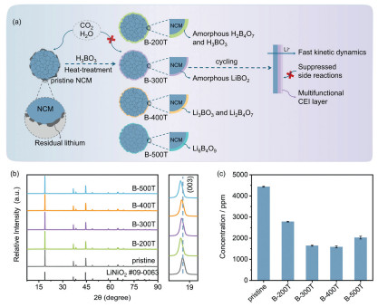
As shown in Fig. 1a, a simple solid-state method enables the in situ conversion of residual surface alkali species into a fast lithium-ion conductor (LBO) using glassy H3BO3. Furthermore, distinct lithium borate phases were obtained under varying thermodynamic conditions. X-ray diffraction (XRD) analysis revealed that all samples maintained the characteristic hexagonal layered α-NaFeO2 structure with R-3m space group (Fig. 1b). The distinct splitting of the (006)/(012) and (018)/(110) peaks in all samples indicates well-ordered layered structures [36,37]. Following heat treatment, the (003) peak shifted slightly to lower angles, which may be due to the partial extraction of Li+ from the NCM reacting with boric acid. The absence of signal peaks corresponding to boron-containing compounds in the coated samples is attributed to the minimal boron content used. The Rietveld refinement results are shown in Fig. S1 and Table S1 (Supporting information), A slight increase in the Li+/Ni2+ mixing degree was observed in B-400T and B-500T compared to the pristine and lower-temperature treated samples (B-200T and B-300T). This trend is linked to the increased disorder of transition metal lattice at higher temperatures [38]. The amount of surface residual lithium compounds (Li2CO3 and LiOH) was measured using electrochemical titration. Fig. 1c summarizes the data on residual lithium before and after H3BO3 coating at different temperatures. For the pristine sample, a certain amount of residual lithium compounds was present on the surface before treatment, with a total residual lithium content of approximately 4434 ppm. After H3BO3 surface treatment, the residual lithium content decreased to varying degrees. Notably, B-300T and B-400T exhibited significantly lower surface residual lithium contents, measuring 1645 and 1586 ppm, respectively.
Figure 1
Figure 1.
(a) Schematic illustration of various coating layers produced through heat treatment at different temperatures and the multifunctional CEI layer formed by amorphous LiBO2 on the surface of B-300T after cycling. XRD patterns (b) and the residual lithium content (c) of all cathode materials.
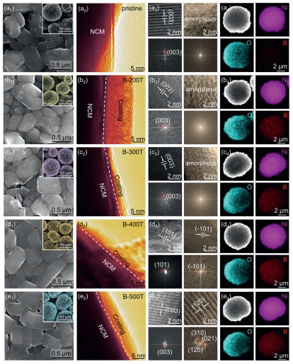
SEM analysis was employed to delineate the morphology of the samples, as depicted in Figs. 2a1-e1. Both uncoated and coated materials consisted of analogous spherical secondary particles, with the coating process preserving the granular dimensions and primary particle morphology of the polycrystalline layered materials. The bare NCM surface is rough, with many irregularly shaped residual lithium impurities on the primary particles. For B-200T and B-300T, a marked reduction in surface impurities was observed, with the primary particles acquiring a glass-like substance coating. With elevated coating temperatures, B-400T and B-500T exhibited exceptionally smooth surfaces, showcasing a uniformly distributed coating over the primary particle surfaces. To further characterize the micro-morphology and crystal structure of the pristine and coated samples, HRTEM and corresponding fast Fourier transform (FFT) analyses were conducted (Fig. 2). The pristine NCM surface contains visible fragments of amorphous Li2CO3. In contrast, the boric acid-coated material exhibits a uniform coating layer, while the intrinsic crystal structure of the bulk NCM remains intact. As the temperature rises, the melting and migration of H3BO3, coupled with its reaction with residual lithium, lead to the thinning of the coating layer. Further temperature increases cause Li+ to migrate from the bulk material to the surface, promoting the growth of the coating layer. (Figs. 2a2-e2). Specifically, B-200T and B-300T samples only showed amorphous structures on the surface. In the B-400T sample, the presence of Li3BO3 was detected, with the lattice spacings of 0.3258 nm, corresponding to the (101) crystal plane of Li3BO3. The surface of B-500T sample exhibited lattice fringes and FFT patterns consistent with Li6B4O9 (Figs. 2a3-e3). Elemental mapping (Figs. 2a4-e4), demonstrated a uniform distribution of Ni and O elements across all samples. Additionally, the uniform distribution of B in the coated samples confirmed that the solid-state method achieved a homogeneous H3BO3 coating on the NCM surface.
Figure 2
Figure 2.
SEM images, TEM images, HRTEM images and corresponding FFT calculated of (a1-a3) pristine NCM, (b1-b3) B-200T, (c1-c3) B-300T, (d1-d3) B-400T, (e1, e2, d3) B-500T. EDS mapping of Ni, O and B for corresponding cathode materials (a4, b4, c4, e4).
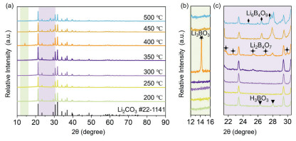
In the Li-B-O ternary system includes several possible phases such as LiBO2 (Li2O·B2O3), Li3BO3 (3Li2O·B2O3), and Li6B4O9 (3Li2O·2B2O3), which can exist in either crystalline or amorphous forms [39]. To analyze the types of interfacial coating substances at different sintering temperatures, a mixture of H3BO3 and Li2CO3 was calcined to simulate the reactions between H3BO3 and residual lithium on the surface of NCM at various temperatures. The surplus Li2CO3 in the blend serves to represent the disproportionately high lithium content within the NCM bulk relative to the H3BO3 coating content, resulting in XRD patterns dominated by Li2CO3 peaks (Fig. 3a). Magnified views in Figs. 3b and c reveal that at 200 ℃, H3BO3 did not completely decompose. Given the difficulty in crystallizing H2B4O7, it is inferred that amorphous H2B4O7 formed in the material surface treated at 200 ℃ [40]. The sample treated at 400 ℃ showed characteristic peaks of Li3BO3 and Li2B4O7. The sample treated at 500 ℃ exhibited characteristic peaks of Li6B4O9, consistent with TEM results. However, at 300 ℃, no specific Li-B-O peaks appeared, and since LiBO2 can be synthesized by melting Li2CO3 and H3BO3 at around 300 ℃ [41], it is hypothesized that the sample treated at 300 ℃ formed amorphous LiBO2.
Figure 3
Figure 3.
(a) XRD pattern of H3BO3/Li2CO3 simulated reactions under different heating temperatures. Enlargement of the XRD pattern of (b) (12.0°–16.0°) and (c) (21.5°–30.5°).
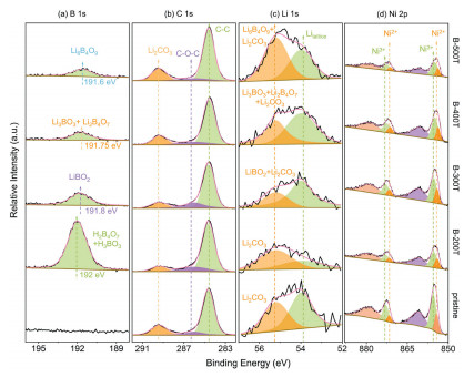
In addition, the XPS spectra (Fig. 4) were analyzed to obtain surface information of the pristine NCM and coated samples. In the B 1s spectra of the modified samples, the peak positions of B-O bonds varied with different sintering temperatures. The peak at 192.3 eV in the B-200T sample corresponds to H2B4O7 and H3BO3, while the peak at 191.8 eV in the B-300T sample is characteristic of LiBO2 [42]. Peaks indicative of Li3BO3 and Li2B4O7 were located around 191.5 [43] and 191.8 eV [44], respectively. Integrating TEM findings and XRD results of H3BO3/Li2CO3 simulated reactions at different heating temperatures, the peak for B-400T at 191.75 eV was assigned to a combination of Li3BO3 and Li2B4O7. Finally, the peak at 191.6 eV in the B-500T sample is considered to be the characteristic peak of Li6B4O9. Based on the different compositions observed in the coating layer of NCM at various calcination temperatures, we infer that as the temperature increases, the following chemical reactions and occur on the surface of material (Table S2 in Supporting information):
4H3BO3→ΔH2B4O7+5H2O
(1)
H2B4O7+2Li2CO3→Δ4LiBO2+2CO2+H2O
(2)
H2B4O7+4LiOH→Δ4LiBO2+3H2O
(3)
Figure 4
Figure 4.
XPS spectra of the pristine NCM, B-200T, B-300T, B-400T and B-500T powders in (a) B 1s, (b) C 1s, (c) Li 1s and (d) Ni 2p.
Notably, it was observed that as the sintering temperature increased, the B peaks intensity decreased, suggesting that higher temperatures accelerated the flow of H3BO3, leading to a more uniform coating on the particle surfaces. The C 1s spectra showed a peak around 289.4 eV, corresponding to O-C=O bonds, reflecting the surface content of Li2CO3. The intensity of the Li2CO3 peak decreased in 200, 300, and 400 ℃ coated samples, each for distinct reasons. For B-300T and B-400T samples, the surface Li2CO3 is transformed into LiBO2 and a coating layer of Li3BO3 and Li2B4O7, respectively. In contrast, the diminished Li2CO3 peak intensity for the B-200T resulted from H2B4O7 and H3BO3 coverage, as evidenced by the weakened intensity of both the Li2CO3 and lattice Li peaks in the Li 1s spectrum. Although the consumption of surface residual lithium during the formation of Li6B4O9 in the 500 ℃ coated sample, the intensity of the Li2CO3 peak does not diminish, suggesting that the elevated temperature prompted lithium migration from the NCM bulk, forming residual lithium impurities on the surface again. This is supported by the heightened peak intensity at 55.2 eV in the Li 1s spectrum of B-500T. In the Li 1s spectrum (Fig. 4c), the peak positions of various LBO compounds are very close to that of Li2CO3, resulting in overlap. Specifically, the peak positions of Li2CO3 and LiBO2 are at approximately 55.12 and 55.2 eV, respectively [43,45], and the significant reduction in peak intensity in the Ni 2p spectra of all coated samples (Fig. 4d) further confirms the presence of a coating layer on the surface of the NCM particles.
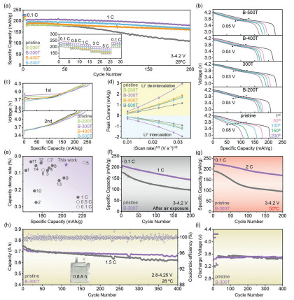
To evaluate the electrochemical performance, cyclic and rate capability were conducted within a voltage range of 2.8–4.3 V (Fig. 5a). It is evident that the surface boron coating significantly enhanced the cyclic stability of NCM cathode. After 200 cycles, the discharge capacity retention rate of the pristine NCM cathode was only 61.58%, while the retention rates for B-200T, B-300T, B-400T, and B-500T were 92.46%, 88.51%, 87.81%, and 87.42%, respectively. Fig. S2 (Supporting information) displays the initial cycle capacities and coulombic efficiencies of all cathodes. The in-situ converted LiBO2 coating on B-300T effectively reduces polarization, thereby enhancing sodium storage performance. However, its initial coulombic efficiency is slightly lower, which may be attributed to the self-sacrificial reaction of the LiBO2 coating and the formation of a uniform, dense CEI on the surface. The rate performance was evaluated at various current density from 0.1 C to 5 C (inset in Fig. 5a). The coated cathode demonstrated superior rate capabilities compared to the pristine NCM. Notably, the B-300T cathode maintained a high discharge capacity of around 183 mAh/g even at a high current rate of 5 C. Among the samples, B-300T exhibited the best electrochemical performance, balancing outstanding cycling stability, high capacity, and excellent rate performance. The discharge curves across varying cycle counts (Fig. 5b), indicate that post 200 cycles, B-300T exhibited the minimal decline in midpoint voltage (Fig. S3 in Supporting information) and retained a reversible capacity of 179.67 mAh/g, whereas the pristine NCM only provided 109.25 mAh/g. This finding further demonstrates that LiBO2 coating layer obtained by low-temperature H3BO3 treatment at 300 ℃ significantly enhances the practical performance of NCM cathode materials. The initial charging curves delineated in Fig. 5c showcase a pronounced elevation in the voltage plateau for B-300T, divergent from the other samples. Moreover, its capacity increase during charging is the slowest, resulting in a higher capacity at the end of the charge state. This suggests that the LiBO2 coating layer contributes to the suppression of polarization. The cyclic voltammetry (CV) curves at varying scan rates (Fig. S4 in Supporting information). At a scan rate of 1 mV/s, the potential differences between the oxidation and reduction peaks for B-200T, B-300T, B-400T, and B-500T electrodes are 0.268, 0.216, 0.199, and 0.301 V, respectively, which are considerably smaller than the 0.537 V of the pristine NCM. This indicates that surface boron modification enhances electrochemical reversibility and reduces interfacial polarization. Furthermore, there is a linear relationship between the peak current and the square root of the scan rate in the CV tests (Fig. 5d). The slope reflects the diffusion-controlled behavior of Li+ in the electrode material. The results indicate that the B-300T electrode has the highest Li+ diffusion coefficient, demonstrating the best Li+ kinetic. The electrochemical impedance spectroscopy (EIS) spectra fitting results (Fig. S5 in Supporting information) obtained before cycling further confirm that B-300T exhibits the lowest charge transfer impedance. This superior ion transport property is the primary reason for its excellent rate performance. Additionally, a comparative analysis of our work with previous studies on boric acid coating reveals the superior overall electrochemical performance of our samples (Table S3 in Supporting information and Fig. 5e). This comparison provides further insights into how temperature influences the composition of the coating layers. The superior electrochemical performance is attributed to the amorphous LiBO2 coating on B-300T surface. LiBO2 offers several advantages over other lithium-rich borates. Its lower viscosity reduces hygroscopicity and lithium carbonate retention [46]. Moreover, its amorphous structure facilitates the formation of a functional CEI layer during cycling, enhancing the overall electrochemical performance.
Figure 5
Figure 5.
Electrochemical performance and kinetic analysis of pristine NCM, B-200T, B-300T, B-400T and B-500T samples. (a) cycling performances during 200 cycles at 1 C rate and rate capabilities. (b) The discharge curves and midpoint voltage decay trend (1st, 50th, 100th, 150th, 200th). (c) Initial and second lap charge curves. (d) Linear fitting relationship of peak current density (Ip) and the square root of the scan rate (ν1/2) for various scan rates CV curves. (e) Electrochemical performance (capacity decay rate per cycle and discharge capacity of first cycle) comparison between this work and reported literatures (The numbers refer to the entries in Table S3). (f) cycling performance after 7 days of exposure to ambient air. (g) Cycling performance at high temperature. (h) Pouch cells cycling performances with (i) the corresponding average discharge voltage.
In order to further highlight the enhancements in material performance provided by the amorphous LiBO2 coating, we evaluated the air stability of the materials and their cycling performance under extreme conditions. Fig. S6 (Supporting information) demonstrates that after seven days of air exposure, the Li2CO3 impurities on the surface of B-300T particles were significantly reduced compared to those on pristine NCM particles. Furthermore, the value of Rct derived from EIS fitting was lower. As shown in Fig. 5f, when the exposed materials were assembled into coin cells and cycled 200 times at 1 C, B-300T achieved a reversible capacity of 143.5 mAh/g and a retention rate of 69.2%, markedly higher than the pristine NCM electrode (97.3 mAh/g and 54.9%). The amorphous LiBO2 coating effectively improves the air stability of the material, which is expected to significantly lower storage costs during large-scale production. High temperatures accelerate oxygen release and structural degradation, leading to detrimental interfacial side reactions, harmful phase transitions, and lattice oxygen release. While all materials exhibited enhanced capacity at 50 ℃ compared to room temperature, they also experienced a faster performance decline (Fig. 5g). Notably, B-300T maintained a capacity retention rate of 76.0%, significantly higher than 49.8% of the pristine NCM, further validating the protective effectiveness of the amorphous LiBO2 coating. We also assessed the cycling stability of the material in pouch full batteries relative to graphite anodes, further exploring the practical application of this interfacial modification approach (Fig. 5h and Table S4 in Supporting information). After 400 cycles at a current density of 1.5 C, the B-300T||Gr cell, with a capacity of 0.8 Ah, retained 91.12% of its capacity, significantly outperforming the commercial pristine NCM cell, which retained only 82.51%. As shown in Fig. 5i, the B-300T||Gr cell maintained a nearly stable median voltage around 3.5 V throughout the cycling process, while the pristine NCM||Gr cell exhibited more considerable voltage instability early in the cycles, with a significant drop in voltage after 400 cycles. High mass loading electrochemical measurements (Fig. S7 in Supporting information) demonstrate that B-300T delivers superior electrochemical performance relative to the pristine NCM sample. Moreover, differential scanning calorimetry (DSC) analysis was conducted to assess structural stability under high temperatures (Fig. S8 in Supporting information). When subjected to heat, materials experienced structural degradation and phase changes, leading to Me-O bond cleavage and lattice oxygen release, which produced considerable heat and posed safety risks. The exothermic onset temperature of B-300T was higher than that of the pristine NCM (240.8 ℃ vs. 220.5 ℃), with a lower heat release.
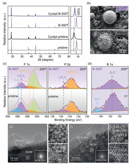
To elucidate the impact of the amorphous LiBO2 coating on the degradation mechanisms of cycling performance, we conducted further analyses of the cathode materials post-cycling. Fig. 6a presents the XRD patterns of fresh and cycled (200 times) pristine NCM and B-300T. Both materials retained their layered structure after cycling; however, the (003) peak for B-300T was stronger and narrower than that of pristine NCM, indicating reduced lattice distortion during the 200 cycles. The adjacent magnified image clearly shows that the (003) diffraction peak of B-300T shifted less than that of pristine NCM, suggesting that diminished lattice distortion facilitates more reversible phase transitions, attributed to the protective effect of the amorphous LiBO2 coating. Fig. 6b reveals noticeable microcracks in the cycled pristine NCM particles, while B-300T particles remained intact, demonstrating that the surface coating alleviates stress and suppresses particle cracking. XPS analysis was performed to explore the composition of the CEI (Figs. 6c and d, Fig. S9 in Supporting information). The C=O and O-C-O signals correspond to organic compounds generated from the decomposition of carbonate solvents, while metal salts composed of F and P primarily arise from the decomposition of LiPF6. After the initial cycle, the F 1s peak of pristine NCM was stronger than that of B-300T, indicating more severe side reactions on the pristine NCM surface during early cycling (Fig. S10 in Supporting information). After 200 cycles, Fourier transform infrared (FTIR) analysis (Fig. S11 in Supporting information) reveals that B-300T exhibits stronger RCO2Li/ROCO2Li peaks, indicating that the amorphous LiBO2 layer effectively suppresses the further decomposition of organic compounds species. No significant differences were observed in the components corresponding to P 1s between the coated material and pristine NCM. Notably, The F 1s spectrum of B-300T prominently displays a strong LiF peak, a finding further corroborated by consistent results from FTIR analysis. This indicates a high content of beneficial LiF in the CEI layer, which enhances its mechanical strength and structural stability. Further analysisof the B 1s XPS spectra of B-300T after the first and 200th cycles (Fig. 6d) reveal that, during initial cycling, direct interaction between the electrolyte and amorphous LiBO2 forms trace BF4⁻ anions in the IHL [47]. These anions facilitate the development of a robust and LiF-rich CEI [48]. As cycling progresses, the dense CEI layer gradually envelops the entire particle surface, with the XPS spectrum eventually showing only B-O peaks. The dynamic evolution mechanism of the CEI for B-300T can be summarized as follows: During the initial cycling stage, the LiBO2 coating undergoes a self-sacrificial reaction upon direct contact with the electrolyte, generating trace amounts of BF4⁻ anions within the IHL. This interfacial chemical process induces the subsequent enrichment of robust inorganic LiF. During long-term cycling, a uniform and dense LiF-rich CEI fully covers the particle surface. At this stage, the LiBO2 coating and the stabilized CEI form a dual-passivation barrier, ensuring a stable electrode interface.
Figure 6
Figure 6.
Structure characterizations and surface composition of pristine NCM and B-300T cathode materials after cycling: (a) XRD patterns, (b) SEM images and (c) XPS spectra after 200 cycles. (d) XPS spectra of B 1s for B-300T after the first and 200th cycles. HRTEM images with FFT results and local enlarged views of the 200th cycled (e) pristine NCM and (f) B-300T cathodes.
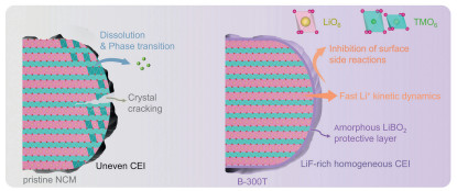
To illustrate the influence of the amorphous LiBO2 coating on CEI formation, TEM was employed to examine the interfacial conditions of the cycled materials (Figs. 6e and f). The CEI layer on pristine NCM was thick and uneven, impeding Li+ transport. In contrast, the CEI on B-300T particles was more uniform and significantly thinner, measuring just 6.6 nm. This suggests that the amorphous LiBO2 coating on B-300T promotes the uniform growth of the CEI during cycling. Additional, on the particle surface, Region Ⅰ of pristine NCM exhibits a rock-salt NiO phase, indicating the occurrence of detrimental irreversible phase transitions, which is likewise supported by the XPS results showing more Ni2+ peaks (Fig. S12 in Supporting information). In contrast, Region Ⅲ of B-300T retains a well-preserved layered structure. Fourier transform analysis of the image also revealed that while pristine NCM exhibited amorphous structural features, the coated sample retained its layered structure, further demonstrating the protective efficacy of the coating in preserving the crystal structure. Furthermore, Fig. S13 (Supporting information) presents the EIS spectra after 200 cycles, along with the equivalent circuit model and fitting results. Compared to the pristine NCM, which has an RCEI of 22.07 Ω and an Rct of 124.30 Ω, the coated samples show varying degrees of reduction in both RCEI and Rct. Among them, the B-300T sample exhibits the lowest Rct (62.70 Ω), indicating that the amorphous LiBO2 coating assists the growth of a multifunctional CEI layer during the cycling process, which lowers the energy barrier for Li+ migration, thus improving charge transfer kinetics [9]. Overall, the amorphous LiBO2 coating on the surface of B-300T facilitates the formation of a robust and uniform CEI layer through the following mechanisms (Fig. 7). First, the LiBO2 layer acts as a protective barrier and enhances Li+ kinetics, reducing side reactions between the highly oxidative nickel-rich cathode and the electrolyte during early cycling stages. This effectively suppresses excessive CEI growth. Second, when the LiBO2 surface reacts with the electrolyte, it forms BF4⁻ anions in the IHL, which promote the formation of a robust and homogeneous multifunctional CEI layer enriched with LiF.
Figure 7
Figure 7.
Failure mechanism schematic of the pristine NCM cathode and schematic diagram of the effect of amorphous LiBO2 coating on the B-300T surface.
In summary, this study utilized a solid-state method to achieve in-situ coating with H3BO3, converting residual lithium on the material surface into a mechanically robust and ionically conductive LBO coating layer. The composition of the surface LBO coating layer varies with different sintering temperatures: At 200, 300, 400, and 500 ℃, the surface coating layers consist of amorphous H2B4O7 and H3BO3, amorphous LiBO2, Li3BO3 and Li2B4O7, Li6B4O9, respectively. Notably, the amorphous LiBO2 coating layer on the surface of B-300T maintains particle integrity, mitigates irreversible phase transitions and interfacial side reactions, and induces the formation of a stable functional CEI layer during cycling. Consequently, after 200 cycles, the B-300T electrode retained a reversible capacity of 179.67 mAh/g with a discharge capacity retention rate of 88.51% and a 0.8 Ah pouch-type full cell exhibited a negligible 8.88% capacity loss after 400 cycles. This study elucidates the optimal phase of the LBO coating layer and provides insights into the impact of surface coating layers on the CEI layer. It offers a simple and effective strategy for enhancing the electrochemical performance of nickel-rich layered oxide cathodes, making it suitable for large-scale commercial production.
Declaration of competing interest
The authors declare that they have no known competing financial interests or personal relationships that could have appeared to influence the work reported in this paper.
This work was supported by the National Key Research and Development Program (No. 2022YFC3900905), the National Natural Science Foundation of China (Nos. 52234001, 52074119), the Science and Technology Planning Project of Hunan Province (No. 2018TP1017), National Innovative Entrepreneurship Training Program for Undergraduates (No. 202300078003).
Supplementary materials
supplementary material associated with this article can be found, in the online version, at doi:10.1016/j.cclet.2025.111228.
Figure 1
(a) Schematic illustration of various coating layers produced through heat treatment at different temperatures and the multifunctional CEI layer formed by amorphous LiBO2 on the surface of B-300T after cycling. XRD patterns (b) and the residual lithium content (c) of all cathode materials.
Figure 2
SEM images, TEM images, HRTEM images and corresponding FFT calculated of (a1-a3) pristine NCM, (b1-b3) B-200T, (c1-c3) B-300T, (d1-d3) B-400T, (e1, e2, d3) B-500T. EDS mapping of Ni, O and B for corresponding cathode materials (a4, b4, c4, e4).
Figure 3
(a) XRD pattern of H3BO3/Li2CO3 simulated reactions under different heating temperatures. Enlargement of the XRD pattern of (b) (12.0°–16.0°) and (c) (21.5°–30.5°).
Figure 5
Electrochemical performance and kinetic analysis of pristine NCM, B-200T, B-300T, B-400T and B-500T samples. (a) cycling performances during 200 cycles at 1 C rate and rate capabilities. (b) The discharge curves and midpoint voltage decay trend (1st, 50th, 100th, 150th, 200th). (c) Initial and second lap charge curves. (d) Linear fitting relationship of peak current density (Ip) and the square root of the scan rate (ν1/2) for various scan rates CV curves. (e) Electrochemical performance (capacity decay rate per cycle and discharge capacity of first cycle) comparison between this work and reported literatures (The numbers refer to the entries in Table S3). (f) cycling performance after 7 days of exposure to ambient air. (g) Cycling performance at high temperature. (h) Pouch cells cycling performances with (i) the corresponding average discharge voltage.
Figure 6
Structure characterizations and surface composition of pristine NCM and B-300T cathode materials after cycling: (a) XRD patterns, (b) SEM images and (c) XPS spectra after 200 cycles. (d) XPS spectra of B 1s for B-300T after the first and 200th cycles. HRTEM images with FFT results and local enlarged views of the 200th cycled (e) pristine NCM and (f) B-300T cathodes.


 DownLoad:

 下载:
下载:


 下载:
下载:

