Figure 1.
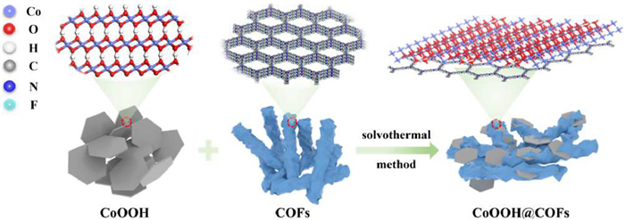
Synthesis and chemical structures of CoOOH@COFs.
CoOOH@COFs S−scheme heterojunction for efficient triclosan degradation in photocatalytic-peroxymonosulfate activation system: Enhanced interfacial electron transfer mechanism
Lu Zhang , Baohua Wang , Wei Yang , Lunan Ju , Zihan Fu , Lei Zhao , Yunqi Jiang , Hongyan Wang , Xiansheng Wang , Cong Lyu

Triclosan (TCS) as a lipid-soluble and broad-spectrum antibacterial has been extensively utilized in pharmaceuticals and personal care products (PPCPs) [1–3]. The ubiquitous use of TCS has inevitably led to its detection in surface water, groundwater, wastewater, drinking water, sediments, and even humans, which poses a serious threat to the public and ecosystems [4–6]. However, the degradation of TCS by traditional treatment is not only inefficient, but the degradation intermediates may be more toxic (e.g., dioxins and other chlorinated derivatives) [7–9]. Therefore, it is critically urgent to develop an efficient process to remove the refractory TCS from water.
The sulfate radical–based advanced oxidation processes (SR–AOPs) have become the more efficient and promising technologies for the treatment of TCS [10,11], mainly due to lower cost, greater redox potential, broader pH application range, superior oxidation selectivity, and stronger chemical stability [12,13]. According to our previous research, as a novel heterogeneous cobalt-based catalyst, cobalt oxyhydroxide (CoOOH) exhibited better catalytic performance than Co3O4 and CoFe2O4 [14,15]. In addition, the photogenerated electrons of the CoOOH photocatalyst reacted with PMS, which enhanced the electron transfer and reactive species generation, thereby improving the PMS activation and refractory organic pollutants degradation [16]. However, due to the narrow bandgap of CoOOH (about 2.1–2.5 eV), photogenerated electron-hole pairs were still easy to recombine [17,18]. Simultaneously, Co ions inevitably leached from CoOOH, causing the risk of secondary pollution and even reducing its catalytic performance [19]. Therefore, using carbon-based catalysts to form a heterojunction structure can effectively increase the specific surface area, regulate the bandgap structure, accelerate electron transfer, and improve chemical stability, thereby the photocatalytic activity will be enhanced [20,21]. In addition, N-doped carbon-based catalysts were reported to be beneficial for refractory organic pollutants degradation, which can activate PMS to generate non-radicals [22–24]. Therefore, the targeted exploration of carbon-based catalysts with an N-rich structure is inevitable.
Compared with other carbon-based catalysts (such as graphene, reduced graphene oxide), triazine-based covalent organic framework (COFs), as an ordered porous crystalline material, have shown broad prospects in the field of photocatalysis and PMS catalysis owiir many fascinating properties [25–27]. In detail, due to the advantages of adjustable pore size, orientation-designed structure, large specific surface area, and exceptional chemical stability, COFs are used to construct heterojunctions with metal materials with suitable or matching bandgaps to improve photocatalytic performance and reduce metal ion leaching [28,29]. However, owing to the intrinsic defects of the triazine structure, the absorption of visible light by COFs is still limited, and it is necessary to enhance the photogenerated carrier separation and interfacial electron transfer [30].
The introduction of halogens can adjust the electron cloud structure of the triazine-based COFs to form a donor-acceptor (D-A) type, which enhances visible light absorption, charge separation, and intramolecular electron transfer [31–34]. Among them, fluorine (F) provides sufficient hydrophobicity for COFs due to the strongest electronegativity, which is conducive to the adsorption and surface reaction of hydrophobic TCS [35]. In addition, compared to the traditional type Ⅱ heterojunction, the S−scheme heterojunction shows higher separation of photogenerated carriers and stronger redox ability [36,37]. More importantly, the performance and mechanism of the heterojunction constructed by COFs and CoOOH to activate PMS under visible light irradiation remains to be explored in depth.
Herein, we constructed the CoOOH@COFs S−scheme heterojunction to efficiently degrade TCS in the photocatalytic-PMS activation system. The morphology, crystal structure, electronic structure, and visible light photocatalytic potential of the CoOOH@COFs have been studied in detail in comparison with pristine CoOOH and COFs. Through XPS and DFT calculations, the underlying mechanism of synergistically efficient TCS degradation by the photocatalytic-PMS activation system was revealed. Additionally, the dominant reactive species and the potential TCS degradation pathways were identified. This paper sheds new perspectives on the rational design of novel S−scheme heterojunction photocatalysts for sustainable and efficient degradation of refractory organic pollutants.
The Supporting information includes the process of preparation, characterization, experimental methods, and analysis methods. The CoOOH@COFs composite was consequently synthesized by solvothermal reaction (Fig. 1), which selected COFs as the carbon carriers to support CoOOH (Fig. S1 in Supporting information). The X-ray diffraction (XRD) examined the crystalline structures of the COFs, CoOOH, and CoOOH@COFs. The diffraction peaks of CoOOH@COFs at 2.9°, 20.2°, and 38.9°, which could be assigned to the (100) facet of COFs [38], and the (003) and (012) facets of CoOOH, respectively (Fig. 2a). Therefore, CoOOH@COFs was successfully synthesized and kept the crystal structure of COFs and CoOOH.
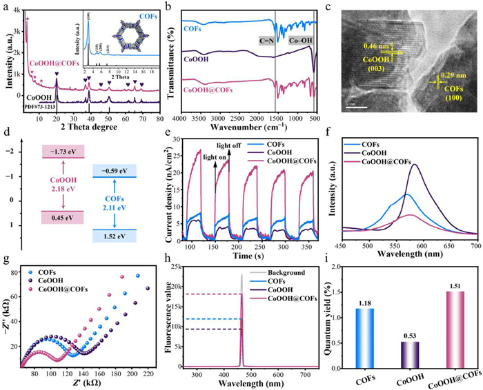
The Fourier-transform infrared spectroscopy (FTIR) spectra of CoOOH@COFs displayed the characteristic peaks corresponding to Co–OH (581 cm−1) of CoOOH (Fig. 2b). The peaks at 1577 cm−1 corresponded to the stretching vibration C=N bond, indicating the successful formation of the imine bond. Meanwhile, the decrease in the intensity of peaks at 1697 cm−1 and 3400 cm−1 arose from C=O and N–H stretching, indicating the consumption of the aldehyde and amino groups (Fig. S2 in Supporting information) [39]. Additionally, the fundamental structure of COFs was not disrupted. As a result, the above discussion verified the successful construction of CoOOH@COFs.
The morphology and structure of the photocatalysts were explored by scanning electron microscope (SEM) analysis. COFs performed the morphology of nanoclusters, while CoOOH consisted of nanosheets (Fig. S3 in Supporting information). Furthermore, the CoOOH nanosheets of CoOOH@COFs could be evenly distributed on the COFs nanoclusters and there was no obvious agglomeration (Fig. S4a in Supporting information). Also, chemical mapping showed the distribution of elements (e.g., C, N, O, F, and Co) on the CoOOH@COFs surface by colored dots, which indicated that the elements were regularly distributed on the photocatalyst surface (Figs. S4b-f in Supporting information). To further demonstrate the successful synthesis and element distribution of CoOOH@COFs, EDS analysis for the weight percentage of each element was carried out (Fig. S4g in Supporting information). High-resolution transmission electron microscopy (HRTEM) images showed the most direct evidence of the microstructure of CoOOH@COFs, which showed distinct lattice fringes (Fig. 2c). The crystal plane spacing of 0.46 nm was assigned to the (003) planes of CoOOH. Furthermore, the interplanar distance of 0.29 nm corresponded to the (100) planes of COFs. Therefore, the CoOOH@COFs possessed highly ordered structures and superior crystallinity. In addition, the sorption isotherms of CoOOH@COFs displayed type-Ⅱ isotherms, indicating the presence of abundant mesoporous in their frameworks (Fig. S5 in Supporting information). The specific surface areas of CoOOH@COFs were determined as 1094 m2/g, which possessed more specific surface areas than CoOOH [40], which was favorable for increasing photocatalytic active sites. As a result, the CoOOH@COFs exhibited larger specific surface areas and more active sites than CoOOH, both of which were favorable for PMS activation.
The ultraviolet-visible diffuse reflectance spectroscopy (UV–vis DRS) spectrum (Figs. S6a and c in Supporting information) illustrated the UV and visible light response of COFs and CoOOH. As calculated from the Kubelka-Munk function ((αhv)2 = A (hv – Eg)) [41], the band gap energies (Eg) of COFs and CoOOH were 2.11 eV and 2.18 eV, respectively. Simultaneously, the X-ray photoelectron spectroscopy-based valence band spectra (VB-XPS) revealed that the VB of COFs and CoOOH were 1.52 eV and 0.45 eV, respectively (Figs. S6b and d in Supporting information). Based on the Eg = EVB – ECB formula, the CB positions (ECB) of the COFs and CoOOH were −0.59 eV and −1.73 eV, respectively (Fig. 2d). Hence, CoOOH@COFs demonstrated suitable energy band structures and performed excellent potential for visible-light-driven photocatalysis.
More significantly, the photocurrent responses of CoOOH@COFs were roughly 5.0 and 3.3 times those of CoOOH and COFs after five on-off cycles of intermittent illumination (Fig. 2e), indicating decreased carrier recombination and increased electron mobility. The photoluminescence spectroscopy (PL) emission peak of CoOOH@COFs was much lower than that of COFs and CoOOH, indicating that CoOOH@COFs had a lower photogenerated electron-hole pairs recombination, and thus possessed an excellent visible-light-driven photocatalytic ability (Fig. 2f). The arc radius on the electrochemical impedance spectroscopy (EIS) Nyquist plot of CoOOH@COFs was smaller compared to that of CoOOH and COFs, indicating the faster interfacial electron transfer (Fig. 2g). Furthermore, the photocatalytic activity of different photocatalysts was directly assessed by the in-situ quantum yields (QY) [42]. As shown in Figs. 2h and i, CoOOH@COFs had the maximum QY, indicating the high utilization of light quantum. In summary, the CoOOH@COFs had outstanding optical-electrical characteristics and had the potential for photo-assisted PMS activation.
The CoOOH@COFs had better adsorption properties, the adsorption of TCS reached 71.1% within 20 min in the dark, whereas CoOOH can barely adsorb TCS (Fig. S7 in Supporting information). The stronger adsorption of CoOOH@COFs promoted TCS adsorption to the surface of CoOOH@COFs, which enhanced the degradation of TCS by ROS and h+. Considering that the pKa of TCS, pKa2 of PMS, and pHpzc of the CoOOH@COFs was 7.8, 9.4, and 7.8 (Fig. S8 in Supporting information), respectively, electrostatic attraction existed between the CoOOH@COFs and HSO5− in the range of 3–9, which promoted PMS activation. In a 20-min reaction, 90.1% of TCS was removed in the Vis-CoOOH@COFs system. In contrast, only 83.8% and 4.9% were achieved in Vis-COFs and Vis-CoOOH systems, respectively (Fig. 3a). It was demonstrated that the heterogeneous structure of CoOOH@COFs reduced the photogenerated carrier recombination, further improving the photocatalytic performance. Under the photocatalytic-PMS activation system, 100% of TCS was degraded by CoOOH@COFs within 8 min and the reaction rate constant reached 0.456 min–1, which was about 2.36 and 1.16 times that of a single PMS system and visible light system, respectively (Figs. 3b and c). Finally, compared with state-of-the-art catalysts in the existing literature for TCS degradation, CoOOH@COFs had remarkable degradation capabilities under similar conditions (Fig. 3d and Table S1 in Supporting information). The superior photocatalytic activity of CoOOH@COFs was attributed to the synergistic effect among photocatalyst, PMS, and visible light.
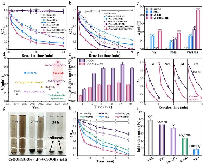
To determine the reusability of CoOOH@COFs, we performed consecutive cycle experiments. The leached Co(Ⅱ) ions from CoOOH@COFs after degradation were < 0.12 mg/L, which was lower than that from CoOOH (0.22 mg/L) (Fig. S9 in Supporting information). Meanwhile, the cumulative leaching rate of Co(Ⅱ) was 0.11 wt% after 20 min in the photocatalytic-PMS activation system (Fig. 3e). The secondary pollution caused by Co ions was smaller than in other systems (Table S2 in Supporting information). Furthermore, the TCS degradation efficiency of CoOOH@COFs remained above 91.0% after four successive cycles (Fig. 3f). The slight decrease in degradation efficiency was due to the intermediates and PMS adsorption on the CoOOH@COFs surface and the minor leaching of metal ions [43]. Compared with CoOOH, CoOOH@COFs efficiently recovered via gravity separation within 20 min (Fig. 3g). Importantly, the mass percentage of recoverable CoOOH@COFs was 94.8%, which was higher than that of CoOOH (91.6%) (Fig. S10 in Supporting information). Hence, CoOOH@COFs had excellent stability and reusability for efficient TCS degradation in the photocatalytic-PMS activation system.
To determine the role of multiple ROSs, quenching experiments were performed using p-BQ, FFA, Na2C2O4, MeOH, and TBA as scavengers of O2•−, 1O2, h+, SO4•−, and •OH, respectively (Table S3 and Fig. S11 in Supporting information) [44]. In the photocatalytic-PMS activation system, the TCS degradation rates of 86.7% and 97.5% were almost unaffected by the introduction of MeOH or TBA, indicating that neither SO4•− nor •OH were the dominant active species (Figs. 3h and i). In the presence of Na2C2O4 and FFA, the degradation rates decreased to 57.0% and 41.3%, suggesting the involvement of h+ and 1O2 in the TCS degradation. Remarkably, p-BQ significantly decreased the TCS degradation rate to only 6.5%, which indicated the dominance of O2•− in the Vis-CoOOH@COFs/PMS system. In conclusion, both non-radicals (1O2, h+, and e−) and radicals (O2•−, •OH, and SO4•−) generated in the photocatalytic-PMS activation system, of which O2•− played an influential role in TCS degradation.
The spin-trapping agents DMPO and TEMP in the electron spin resonance (ESR) method were explored to further identify the generation of various ROSs in the Vis-CoOOH@COFs/PMS system (Figs. 4a-c) [45]. The characteristic signals of DMPO−•OH, DMPO–SO4•−, DMPO–O2•− and TEMP–1O2 of CoOOH@COFs were stronger than that of CoOOH, demonstrating that abundant •OH, SO4•−, O2•−, and 1O2 were generated in the photocatalytic-PMS activation system. Overall, multiple ROSs participated in the TCS degradation corroborating the findings obtained from quenching experiments.
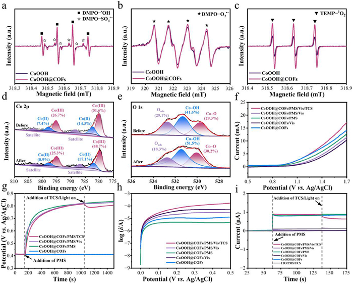
To explore the elemental chemical states of CoOOH@COFs and the potential mechanism of the photocatalytic-PMS activation system, the XPS spectra of Co 2p, O 1s, C 1s, N 1s, and F 1s were detected (Fig. S12 in Supporting information). The several major peaks located at 284.8, 286.2, 287.3, and 288.7 eV in the C 1s signal of CoOOH@COFs were ascribed to the C–C, C=N–C, C–F, and C=N, respectively, confirming the formation of imine bond (C=N), which was consistent with N 1s XPS spectra. For Co 2p spectra, the Co(Ⅲ) content of CoOOH@COFs decreased from 78.3% to 74.0% after the reaction, presumably due to the partial conversion of the Co(Ⅲ) to Co(Ⅱ) (Fig. 4d and Table S4 in Supporting information). In comparison, the relative proportion of Co(Ⅱ) increased from 21.7% to 26.0%, suggesting that the Co(Ⅲ)/Co(Ⅱ) redox cycle participated in the TCS degradation. As shown in Fig. 4e, O 1s spectra of CoOOH@COFs were fitted into lattice oxygen (Co–O), hydroxyl oxygen (Co–OH), and adsorbed oxygen (Oads). The peaks of Oads after the catalytic reaction decreased from 29.1% to 18.3%, presumably due to the participation of H2O. Particularly, the Co–OH content increased from 41.6% to 51.5% resulting from the formation of Co–OH+ species, thereby enhancing PMS activation and promoting ROS generation [46]. In summary, the synergistic TCS degradation mechanism was revealed, which involved the Co(Ⅲ)/Co(Ⅱ) redox cycle and the Co–OH+ species formation in the Vis-CoOOH@COFs/PMS system.
The electron transfer among the CoOOH@COFs, PMS, and TCS was explored to elucidate the synergistic degradation mechanism of the photocatalytic-PMS activation system. The photogenerated electrons were effectively captured by PMS adsorbed on the CoOOH@COFs surface, thus inhibiting charge recombination. The TCS degradation was facilitated by the electron transfer mechanism via a non-radical pathway [47]. In the linear sweep voltammetry (LSV) plots (Fig. 4f), a marked enhancement in current was observed by direct electron transfer when PMS, visible light, and TCS were added simultaneously [48,49]. Meanwhile, the electron transfer was further supported by the chronopotentiometry curves (Fig. 4g). The open-circuit potential of CoOOH@COFs was stabilized at 0.42 V vs. SHE when submerged in the phosphate electrolyte and immediately increased to an equilibrium value of about 0.83 V vs. SHE after the addition of PMS [50]. It was attributed that more PMS was absorbed on the surface of CoOOH@COFs, resulting in the partial electron transfer process. The equilibrium potential decreased after introducing TCS or visible light, indicating that PMS drew e− directly from adsorbed TCS or CoOOH@COFs. Subsequently, the oxidation potential of CoOOH@COFs ultimately decreased with the decomposition of PMS [51]. Meanwhile, the tangent slope of the Tafel curve in the photocatalytic-PMS activation system exhibited a pronounced increase compared to other systems (Fig. 4h), which ascribed to the substantial electron transfer among PMS, TCS, and CoOOH@COFs. Moreover, the amperometric i-t curves of CoOOH@COFs were recorded in Fig. 4i to monitor electron transfer. A positive current appeared immediately with the addition of PMS to the system, demonstrating the electron transfer from CoOOH@COFs to PMS and the CoOOH@COFs-PMS metastable reactive complex generation [52]. The decrease in positive current upon the addition of TCS or visible light suggested the electrons transfer from TCS and CoOOH@COFs to PMS [53]. Accordingly, a direct electron transfer mechanism via a non-radical pathway in the photocatalytic-PMS activation system played a role in the TCS degradation.
Meanwhile, the partial density of states (PDOS) and work function (Ф) supplied more evidence for the S−scheme charge transfer mechanism. The Ф value of COFs (5.44 eV) was higher than that of CoOOH (4.93 eV) (Figs. 5a and b). When COFs and CoOOH were in contact, the electrons spontaneously transferred from CoOOH to COFs until the balance of Fermi level (Ef) was reached (Fig. 5c), inducing the construction of an internal electric field (IEF) with the direction from CoOOH to COFs. The depletion or aggregation of electrons at the interface caused the upward and downward banding of CoOOH and COFs. Under visible light irradiation, the photogenerated electrons in CB of COFs transferred to CoOOH driven by the built-IEF and recombined with the holes in VB of CoOOH (Fig. 5d). Consequently, CoOOH@COFs S−scheme heterojunction was constructed, which could effectively enhance the photogenerated carrier separation and transfer, and maintain strong redox capacity.

In summary, TCS was synergistically degraded by CoOOH@COFs S−scheme heterojunction in the photocatalytic-PMS activation system via both non-radicals (1O2, h+, and e−) and radicals (O2•−, SO4•−, and •OH) pathways, as shown in Fig. 6 (Eqs. 1–13).
|
|
(1) |
|
|
(2) |
|
|
(3) |
|
|
(4) |
|
|
(5) |
|
|
(6) |
|
|
(7) |
|
|
(8) |
|
|
(9) |
|
|
(10) |
|
|
(11) |
|
|
(12) |
|
|
(13) |

The attack sites of TCS were calculated by the Fukui function and the degradation pathway was investigated by frontier molecular orbital (FMO) theory. The TCS molecular model optimized was shown in Fig. S13a (Supporting information). Based on FMO theory, the highest occupied molecular orbital (HOMO) and the lowest unoccupied molecular orbital (LUMO) indicated electron donating and accepting ability, respectively (Figs. S13b and c in Supporting information). The HOMO of TCS was mainly situated at the hydroxyl group, O, and Cl16, which were susceptible to electrophilic attacks. In contrast, the LUMO was majorly distributed in the benzene ring, making it prone to nucleophilic attacks. Moreover, the Fukui index of TCS and condensed density difference (CDD) were explored to predict the attacked active sites, particularly focused on the prediction of sites susceptible to electrophilic (f–), nucleophilic (f+), and radical attacks (f0) (Fig. S13d in Supporting information) [54].
The degradation intermediates of TCS identified by LC-MS/MS (Fig. S14 and Table S4 in Supporting information) and the potential degradation pathways were illustrated in correlation with the mechanism of multiple ROS generation (Fig. S15 in Supporting information). In detail, P0 at m/z 289.01 was detected as TCS. In detail, P1 at m/z 303.96 corresponded to hydroxylated products of TCS. Of them, P2 and P3 at m/z 163.06 and 142.04 arose from the cleavage of the ether bond in TCS. The O2•−, 1O2, •OH and SO4•– acted on P2 and P3 to form chlorobenzene (P4, m/z 113.01). The mineralization of TCS was effectively oxidated to carbon dioxide, water, and other byproducts through the synergistic effects of O2•−, 1O2, •OH, SO4•−, and h+ [55]. The toxicity of TCS and its degradation products were evaluated by the Toxicity Estimation Software Tool (T.E.S.T.). As shown in Figs. S16a and b (Supporting information), all intermediates had higher toxicity LD50 and smaller bioconcentration factor than the parent pollutant. Additionally, most intermediates exhibited non-toxicity and non-mutagenicity (Figs. S16c and d in Supporting information), signifying that the photocatalytic-PMS activation system was highly effective in eliminating ecotoxicity.
In summary, a novel CoOOH@COFs S−scheme heterojunction was elaborately constructed applying for efficient TCS degradation. Specifically, in the photocatalytic-PMS activation system, CoOOH@COFs completely degraded TCS within 8 min with a reaction rate constant of 1.90 times that of CoOOH. The photogenerated electrons facilitated the Co(Ⅲ)/Co(Ⅱ) redox cycle and reacted with PMS to decrease the charge combination. Meanwhile, S−scheme heterojunction greatly promoted photogenerated carrier separation, enhanced interfacial electron transfer, extended charge lifetime, and accelerated PMS activation to generate abundant ROSs. Importantly, both radicals (O2•−, •OH, and SO4•−) and non-radicals (1O2, h+, and e−) were involved in the Vis-CoOOH@COFs/PMS system, in which O2•− was the dominant ROSs in TCS degradation. Besides, the degradation intermediates had lower toxicity than TCS, indicating that CoOOH@COFs was an environmentally friendly photocatalyst. This study provides a theoretical basis and comprehensive reference for the synergetic mechanism of photocatalytic-PMS activation by S−scheme heterojunction photocatalysts for refractory organic pollutants in water environments.
The authors declare that they have no known competing financial interests or personal relationships that could have appeared to influence the work reported in this paper.
Lu Zhang: Writing – original draft, Formal analysis, Conceptualization. Baohua Wang: Writing – original draft, Resources. Wei Yang: Resources. Lunan Ju: Resources, Investigation. Zihan Fu: Resources, Investigation. Lei Zhao: Resources. Yunqi Jiang: Resources. Hongyan Wang: Resources. Xiansheng Wang: Writing – review & editing, Project administration. Cong Lyu: Writing – review & editing, Project administration, Funding acquisition.
Supplementary material associated with this article can be found, in the online version, at doi:
Y. Jiang, L. Liu, B. Jin, et al., Sci. Total Environ. 932 (2024) 173013–173028. doi: 10.1016/j.scitotenv.2024.173013
Z. Wang, X. Li, H. Liu, et al., Crit. Rev. Env. Sci. Tec. 54 (2024) 1340–1363. doi: 10.1080/10643389.2024.2309846
Y. Guo, W. Shi, Z. Liu, et al., J. Hazard. Mater. 459 (2023) 132289–132299. doi: 10.1016/j.jhazmat.2023.132289
Q.E. Yang, X. Ma, M. Li, et al., Nat. Commun. 15 (2024) 3654–3666. doi: 10.1038/s41467-024-48006-9
J.S. Lee, J.S. Lee, H.S. Kim, Sci. Total. Environ. 920 (2024) 170902–170915. doi: 10.1016/j.scitotenv.2024.170902
L. Huang, W. Zhang, D. Tong, et al., Water Res. 233 (2023) 119736–119752. doi: 10.1016/j.watres.2023.119736
X. Qian, L. Xu, Y. Zhu, et al., Chem. Eng. J. 420 (2021) 127615–127624. doi: 10.1016/j.cej.2020.127615
Z. Huang, Q. Lin, N. Cai, et al., Sep. Purif. 276 (2021) 119318–119327. doi: 10.1016/j.seppur.2021.119318
L.W. Olaniyan, N. Mkwetshana, A.I. Okoh, Springerplus 5 (2016) 1639–1655. doi: 10.1186/s40064-016-3287-x
M. Bilal, D. Barceló, H.M.N. Iqbal, Sci. Total Environ. 735 (2020) 139194–139206. doi: 10.1016/j.scitotenv.2020.139194
Z. Huang, Q. Lin, N. Cai, et al., Sep. Purif. 276 (2021) 119318–119326. doi: 10.1016/j.seppur.2021.119318
X. Li, D. Zhang, Z. Liu, et al., Chem. Eng. J. 400 (2020) 125897–125907. doi: 10.1016/j.cej.2020.125897
Z.H. Diao, W. Qian, Z.W. Zhang, et al., Chem. Eng. J. 397 (2020) 125382–125390. doi: 10.1016/j.cej.2020.125382
Q. Zhang, D. He, X. Li, et al., J. Hazard. Mater. 384 (2020) 121350. doi: 10.1016/j.jhazmat.2019.121350
C. Lyu, D. He, Y. Chang, et al., Sci. Total Environ. 680 (2019) 61–69. doi: 10.1016/j.scitotenv.2019.04.324
L. Zhang, L. Ju, X. Li, et al., J. Hazard. Mater. 460 (2023) 132403. doi: 10.1016/j.jhazmat.2023.132403
J. Huang, Q. Shang, Y. Huang, et al., Angew. Chem. Int. Ed. 55 (2016) 2137–2141. doi: 10.1002/anie.201510642
L. Shi, K. Zhao, S. Liu, Mater. Lett. 228 (2018) 121–124. doi: 10.1016/j.matlet.2018.05.134
Q. Yi, J. Tan, W. Liu, et al., Chem. Eng. J. 400 (2020) 125965–125973. doi: 10.1016/j.cej.2020.125965
M. Wang, G. Tan, H. Ren, et al., Appl. Surf. Sci. 492 (2019) 690–702. doi: 10.1016/j.apsusc.2019.06.260
R. Chong, Z. Wang, J. Lv, et al., J. Catal. 399 (2021) 170–181. doi: 10.1016/j.jcat.2021.05.006
Z. Wang, L. Huang, Y. Wang, et al., Environ. Res. 193 (2021) 110537–110547. doi: 10.1016/j.envres.2020.110537
H.B. Qiu, P.C. Guo, L. Yuan, et al., Chin. Chem. Lett. 31 (2020) 2614–2618. doi: 10.1016/j.cclet.2020.08.014
P. Sun, H. Liu, M. Feng, et al., Appl. Catal. B: Environ. 272 (2020) 119005–119015. doi: 10.1016/j.apcatb.2020.119005
Y. Gao, C. Zhi, P. Cui, et al., Chem. Eng. J. 400 (2020) 125967–125977. doi: 10.1016/j.cej.2020.125967
M. Liu, K. Jiang, X. Ding, et al., Adv. Mater. 31 (2019) 1807865–1807871. doi: 10.1002/adma.201807865
Z. Tan, P. Zhang, Q. Chen, et al., Catal. Sci. Technol. 11 (2021) 1874–1880. doi: 10.1039/d0cy02094j
G. Li, J. Ye, Y. Shen, et al., Chem. Eng. J. 421 (2021) 127784–127794. doi: 10.1016/j.cej.2020.127784
Y. He, X. Chen, C. Huang, et al., Chin. J. Catal. 42 (2021) 123–130. doi: 10.1117/12.2589522
Z. Cheng, K. Zheng, G. Lin, et al., Nanoscale adv. 1 (2019) 2674–2680. doi: 10.1039/c9na00089e
W. Chen, L. Wang, D. Mo, et al., Angew. Chem. Int. Ed. 59 (2020) 16902–16909. doi: 10.1002/anie.202006925
D. Cao, J. Guan, J. Du, et al., J. Hazard. Mater. 476 (2024) 134956–134965. doi: 10.1016/j.jhazmat.2024.134956
H. Ye, Z. Wang, F. Yu, et al., Appl. Catal. B: Environ. 267 (2020) 118577–118588. doi: 10.1016/j.apcatb.2019.118577
P.B. Pati, G. Damas, L. Tian, et al., Energy Environ. Sci. 10 (2017) 1372–1376. doi: 10.1039/C7EE00751E
C. Matei Ghimbeu, K. Guerin, M. Dubois, et al., Carbon 84 (2015) 567–583. doi: 10.1016/j.carbon.2014.12.034
Z. Zheng, J. Min, X. Wang, et al., Environ. Sci. Technol. 57 (2023) 8414–8425. doi: 10.1021/acs.est.2c09122
Y. Zhong, S. Ma, D. Chen, et al., Water. Res. 258 (2024) 121774–121785. doi: 10.1016/j.watres.2024.121774
G. Xu, L. Hou, C. Liu, et al., ACS Appl. Mater. Interfaces 13 (2021) 51535–51545. doi: 10.1021/acsami.1c15869
Q. Liao, C. Ke, X. Huang, et al., J. Mater. Chem. A 7 (2019) 18959–18970. doi: 10.1039/c9ta06214a
J. Liu, H. Liu, Q. Pan, et al., Colloids. Surf. 655 (2022) 130314–130324. doi: 10.1016/j.colsurfa.2022.130314
D.E. Zhang, L.Z. Ren, X.Y. Hao, et al., Appl. Surf. Sci. 355 (2015) 547–552. doi: 10.1016/j.apsusc.2015.04.018
X. Li, L. Zhang, S. Niu, et al., J. Hazard. Mater. 444 (2023) 130366–130377. doi: 10.1016/j.jhazmat.2022.130366
M. Yao, M. Xie, S. Zhang, et al., Sep. Purif. 302 (2022) 122145–122155. doi: 10.1016/j.seppur.2022.122145
H. Zeng, H. Zhu, J. Deng, et al., Chem. Eng. J. 442 (2022) 136251–136261. doi: 10.1016/j.cej.2022.136251
Z. Zhang, X. Zhan, B. Hong, et al., J. Colloid. Interf. Sci. 663 (2024) 909–918. doi: 10.1016/j.jcis.2024.03.010
M. Xiong, B. Chai, G. Fan, et al., J. Colloid. Interf. Sci. 638 (2023) 412–426. doi: 10.1016/j.jcis.2023.02.002
X. Li, Z. Liu, Y. Zhu, et al., Sci. Total. Environ. 749 (2020) 141466–141478. doi: 10.1016/j.scitotenv.2020.141466
Y. d. Chen, X. Duan, C. Zhang, et al., Chem. Eng. J. 384 (2020) 123244–123254. doi: 10.1016/j.cej.2019.123244
J. Qin, L. Dai, P. Shi, et al., J. Hazard. Mater. 398 (2020) 122808–122815. doi: 10.1016/j.jhazmat.2020.122808
Y. Yang, P. Zhang, K. Hu, et al., Appl. Catal. B: Environ. 286 (2021) 119903–119913. doi: 10.1016/j.apcatb.2021.119903
W. Ren, L. Xiong, G. Nie, et al., Environ. Sci. Technol. 54 (2020) 1267–1275. doi: 10.1021/acs.est.9b06208
P. Shao, S. Yu, X. Duan, et al., Environ. Sci. Technol. 54 (2020) 8464–8472. doi: 10.1021/acs.est.0c02645
S. Li, J. Huang, X. Li, et al., Chem. Eng. J. 398 (2020) 125529–125538. doi: 10.1016/j.cej.2020.125529
J. Li, J. Chen, Y. Ao, et al., Sep. Purif. 281 (2022) 119863–119875. doi: 10.1016/j.seppur.2021.119863
S. Wang, J. Wang, Chem. Eng. J. 356 (2019) 350–358. doi: 10.1016/j.cej.2018.09.062

Figure 2 Physic-chemical characterization of the COFs, CoOOH, and CoOOH@COFs: (a) XRD, (b) FTIR, and (c) HRTEM images. Photo-electro-chemical characterization of the COFs, CoOOH, and CoOOH@COFs: (d) band alignment, (e) TPR, (f) PL, (g) EIS spectra, (h) in-situ QY in the photocatalytic-PMS activation system and dark conditions, and (i) QY.

Figure 3 The catalytic performance of the COFs, CoOOH, and CoOOH@COFs in (a) visible light photocatalytic system, (b) PMS catalytic oxidation system, and the synergistic system of photocatalytic-PMS activation. (c) The reaction rate constant k of the TCS degradation in the systems. (d) Comparison of the previously reported kinetic rate constants of TCS degradation with this work. (e) The ratio of the mass of Co ions in the solution to the total mass of Co element and (f) TCS degradation efficiency after successive four cycles in the Vis-CoOOH/PMS and Vis-CoOOH@COFs/PMS systems. (g) Gravity separation (i.e., settling) of CoOOH@COFs and CoOOH. (h) The degradation efficiency and (i) inhibition rate of TCS degradation with different quenchers in the Vis-CoOOH@COFs/PMS system. Conditions: [TCS] = 10 mg/L, [Catalysts] = 0.2 g/L, [PMS] = 0.7 mmol/L, [MeOH] = [TBA] = [p-BQ] = [KBrO3] = [Na2C2O4] = [FFA] = 70 mmol/L, initial pH 6, T = 20 ± 1 ℃.

Figure 4 The ESR spectra of (a) DMPO−•OH and DMPO−SO4•–, (b) DMPO−O2•− and (c) TEMP−1O2 adducts in the Vis-CoOOH/PMS and Vis-CoOOH@COFs/PMS systems. High-resolution XPS spectra of CoOOH@COFs before and after the catalytic oxidation process: (d) Co 2p and (e) O 1s. (f) The LSV plots, (g) chronopotentiometry curves, (h) Tafel polarization curves, and (i) amperometric i-t curve measurements upon the addition of PMS and TCS or switching on the visible light using CoOOH@COFs and indium tin oxides (ITO) as the working electrode. Conditions: [TCS] = 10 mg/L, [Catalysts] = 0.2 g/L, [PMS] = 0.7 mmol/L, [Na2SO4] = 0.2 mol/L, T = 20 ± 1 ℃.

Figure 5 (a, b) The partial density of states (PDOS) diagrams of CoOOH and COFs. (c) Schematic diagram of PMS activation mechanism by CoOOH@COFs transition metal and (d) CoOOH@COFs S−scheme heterojunction with interface electric field.

 扫一扫看文章

扫一扫关注我们
 DownLoad:

 下载:
下载:

 下载:
下载: