Received Date:
25 January 2025 Accepted Date:
12 March 2025 Revised Date:
03 March 2025 Available Online:
15 July 2026
Abstract:
The direct utilization of magnesium (Mg) metal as the anode of Mg batteries is significantly susceptible to passivation in conventional electrolytes, which critically hinders Mg plating and stripping. To address this issue, a synergistic effect of the three-dimensional (3D) scaffolds’ dispersive current strategy and the gradient conductivity artificial layer effectively promotes internal reversible Mg plating and stripping. In this study, we have synthesized 3D magnesiophilic gradient conductivity scaffolds (Sn@Ni), featuring an electronic insulation layer, uniform Mg2+ transport channels, and a high specific surface area, through in situ ion-exchange reactions. It is observed that the plate-like metal chloride insulation provides the necessary potential gradient to prevent electrolyte decomposition and Mg deposition on the surface. Furthermore, the magnesiophilic metal tin (Sn) effectively lowers the nucleation barrier of Mg, enhancing the uniform diffusion of Mg. Additionally, the high specific surface area of the nickel foam skeleton effectively mitigates current density and regulates Mg deposition behavior. As a result, the Sn@Ni 3D gradient conductivity scaffolds exhibit an exceptionally low Mg nucleation overpotential (52 mV) under 500 μA/cm2. Moreover, the Sn@Ni-Mg gradient conductivity anode, produced by plating Mg onto Sn@Ni, demonstrates a symmetric cell capable of sustaining an ultra-long stable reversible cycle exceeding 2800 h (5300 cycles). Full cells with Mo6S8 cathode also show an impressive capacity retention of 95.6% after 500 cycles at 1 C. This breakthrough provides a novel approach to anode design, presenting potential advancements for next-generation Mg batteries.
Rechargeable Mg batteries (RMBs) are regarded as promising candidates for future battery technology due to their relatively low reduction potential (−2.37 V vs. SHE), exceptional theoretical volumetric capacity (3832 mAh/cm3, nearly double that of lithium), cost-effectiveness, and superior safety profile [1-5]. Mg(TFSI)2 is often heralded as the "gem" among Mg electrolytes owing to its broad electrochemical window, facile synthesis, excellent ionic conductivity, strong thermal stability, and resistance to corrosion. However, TFSI- and [Mg2+-TFSI-] ion pair can induce side reactions to produce MgO, MgSO3, and MgS, which contribute to the development of a passivation layer with poor ionic conductivity [6-8]. This limited ionic conductivity results in a substantial portion of the total current being consumed by electrolyte reduction reactions, thus leading to further electrolyte decomposition. Consequently, this process leads to a notable increase in the passivation layer thickness, rendering the Mg foil inactive—a phenomenon commonly referred to as "dead Mg" [9]. Furthermore, thicker passivation layers necessitate higher polarization voltages for driving the Mg plating and stripping, resulting in an unstable anode-electrolyte interface and uneven electric field distribution, which ultimately leading to inhomogeneous Mg plating or even short circuits [10]. The presence of passivation layers and inhomogeneous Mg deposition has been shown to result in high overpotentials for Mg plating and stripping, reduced coulombic efficiency, and limited cycle life [11,12].
In recent years, 3D magnesiophilic scaffolds have gained widespread application in Mg metal storage [13]. Various functional materials, including Mg3Bi2 whiskers [10], Ni(OH)2 nanosheet arrays [14], conjugated polyaniline pre-intercalated V2O5 frameworks [15], ZIF-8-coated carbon nanofibers [16], and MgO wrapped Zn skeletons [17], promote uniform nucleation of Mg due to their abundant active sites and strong affinity. However, the idealized anode-electrolyte interface layer should fulfill two critical functions: efficient electronic insulation to prevent electrolyte decomposition and the capacity to facilitate rapid and uniform ion movement. Lv, Zhang, Yang and colleagues developed gradient-conductive protective layers based on tin, germanium, and antimony via ion-exchange reactions to coat the surface of Mg foil [8,18,19]. These artificial gradient layers contain metal chlorides for electronic insulation and alloy components for enhanced ion transport. With the help of metal-based gradient composite artificial layer, the metal anodes are effectively protected, achieving outstanding cycling performance in their symmetrical batteries. Nonetheless, the alloying and de-alloying processes are frequently accompanied by significant volume changes (approximately 214%), potentially causing interlayer cracking and electron leakage [20].
Herein, we propose 3D gradient conductivity scaffolds that integrate a gradient conductivity interface with a current dispersion strategy. Specifically, this is achieved by growing Sn and chloride on the surface of nickel foam (referred to as "Sn@Ni"). Subsequently, Mg metal is electrochemically deposited onto the 3D gradient conductivity scaffolds as anodes (called "Sn@Ni-Mg"). This gradient conductivity anode, featuring surface electron insulation and internal electron conductivity characteristics, effectively mitigates electrolyte decomposition and passivation layer formation while promoting ion transport. The plate-like structure consisting of metal chlorides is uniformly distributed across the surface of the Sn-based metal layer, diffusing the stress and preventing interlayer cracking resulting from alloying/dealloying processes, thereby ensuring structural stability. Moreover, nickel foam with a high specific surface area enables the availability of a small local current even at large apparent currents, resulting in uniform plating morphology. Additionally, the 3D collector not only reduces the local current density to regulate Mg deposition behavior, but also minimizes the damage caused by undesirable deposits due to its large unoccupied area [21,22]. Experimental results show that, under a current density of 0.5 mA/cm2 in the 0.5 Mg(TFSI)2-DME electrolyte, the Sn@Ni 3D gradient conductive scaffold exhibits a low nucleation overpotential (52 mV), demonstrating excellent Mg affinity. Benefiting from the excellent reversibility and kinetics of the gradient electronic insulation structure, Sn@Ni-Mg symmetric cell achieves ultra-long stable cycling of over 2800 h at 0.5 mA/cm2 current density. What’s more, Sn@Ni-Mg//Mo6S8 full cell exhibits superior specific capacity (84.2 mAh/g at 1 C) and cycling stability (capacity retention of 95.6% after 500 cycle). At a higher rate of 5 C, it also displays high specific capacity over 70 mAh/g within 1000 cycles, indicating the immense potential for practical RMBs application.
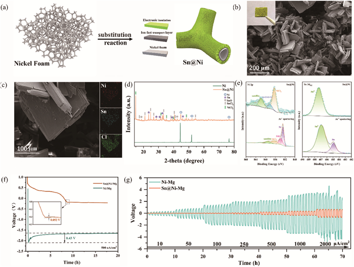
The Sn@Ni 3D gradient conductivity scaffold was prepared through a straightforward ion substitution reaction (Fig. S1 in Supporting information). Specifically, the cleaned nickel foam was immersed in a 0.5 mol/L SnCl4-DME solution, during which the metallic nickel spontaneously underwent ion exchange with SnCl4 (2SnCl4 + 3Ni → Sn + 3NiCl2 + SnCl2) to form a mixed-phase artificial solid electrolyte interphase (SEI) on the surface of the nickel foam (Fig. 1a). Scanning electron microscopy (SEM) was utilized to characterize the morphologies of both the pristine nickel foam and Sn@Ni 3D gradient conductivity scaffolds. The nickel foam is composed of interconnected skeletons approximately 100 μm in diameter, providing large specific surface areas. Energy dispersive X-ray spectroscopy (EDS) elemental distribution graph indicates that the elemental contents of O and Cl on the surface of the cleaned nickel foam are extremely low, confirming the removal of the surface oxide layer (Fig. S2 in Supporting information). In contrast to pure nickel foam, green crystals are observed covering on the entire surface of the Sn@Ni 3D gradient conductivity scaffolds (Fig. 1b), with laminates approximately 200 µm in length and width cross-distributed (Fig. 1c). Moreover, EDS mapping reveals that Sn, Ni, and Cl elements distribute uniformly on the surface of the laminates; further characterization techniques are necessary to accurately determine their composition.
Figure 1
Figure 1.
Schematic of gradient conductivity scaffolds Sn@Ni. (a) Preparation mechanism of Sn@Ni. (b) Surface SEM images of Sn@Ni (Insert: photo of Sn@Ni). (c) Enlarged SEM images and corresponding EDS analysis of Sn@Ni. (d) XRD patterns of nickel foam and Sn@Ni. (e) Ni 2p spectra and Sn 3d5/2 spectra of Sn@Ni (top), and after 200 s Ar+ sputtering (bottom), respectively. (f) Voltage profile of galvanostatic deposition of Sn@Ni//Mg and Ni//Mg cells at 500 μA/cm2. (g) Galvanostatic cycling performances of Ni-Mg and Sn@Ni-Mg anodes under different current densities (from 10 µA/cm2 to 2000 μA/cm2).
The structure and chemistry of the Sn@Ni 3D gradient conductivity scaffolds were analyzed by X-ray diffraction (XRD) (Fig. 1d), revealing the presence of crystalline NiCl2, SnCl2, and metallic Sn on the surface of nickel foam [23-25]. The extra peaks observed in the XRD patterns are attributed to the presence of SnO, a common occurrence when the sample undergoes exposure to air during XRD characterization [26]. Based on EDS mapping analysis, it can be inferred that the layer on the surface of the Sn@Ni gradient conductivity scaffolds is a combination of NiCl2 and SnCl2, indicating the successful construction of an electronic insulation layer on the nickel foam surface. X-ray photoelectron spectroscopy (XPS) was performed to analyze the composition of the Sn@Ni gradient conductivity scaffolds in greater detail. As exhibited in Fig. 1e, the Ni 2p and Sn 3d5/2 spectra of Sn@Ni can be deconvoluted into multiple component peaks, including NiCl2, mesophase Ni-Cl-O-Ni and Sn2+ (peaks located at 856.35, 858.17, and 487.32 eV, respectively) [27-29]. The internal composition of the SEI on the Sn@Ni surface was analyzed through XPS depth profiling. After 200 s of Ar+ sputtering, the amount of NiCl2 was significantly reduced, and diffraction peaks of Ni and NiO appeared at 852.87 and 853.76 eV, respectively [30]. Simultaneously, the peak of metallic Sn (located at 484.91 eV) appeared in the Sn 3d5/2 spectra, indicating the distribution of metallic Sn beneath the electronic insulation layer [31]. In summary, an artificial SEI layer with gradient conductivity has been successfully constructed on the surface of nickel foam, demonstrating the effective integration of both electronic insulation and internal electron conductivity characteristics.
To further investigate the formation process of the surface electronic insulation layer, a series of Sn@Ni gradient conductivity scaffolds were prepared with different reaction times (nickel foam immersed in the 0.5 mol/L SnCl4-DME solution for 12, 24, 36, and 60 h, respectively). SEM images of Sn@Ni at various reaction times reveal that the surface electronic insulation layer consists of two parts: a film structure that grows horizontally on the surface of the nickel foam and a laminate structure that grows vertically atop the substrate (Figs. S3a-c in Supporting information). EDS mapping of the Sn@Ni for 36 h reveals the distribution of Sn, Ni, and Cl, suggesting that the film structure predominantly consists of metallic Sn mixed with SnCl2 (Fig. S3d in Supporting information). It is concluded that the structural arrangement of Sn@Ni is predicated on the framework of nickel foam, specifically forming a dense protective layer consisting of mixed phases of Sn and SnCl2 on its surface. Above the protective layer, laminates composed of NiCl2 and SnCl2 are arranged in a staggered manner and functions as an electronic insulator. To assess the reliability of the assumption, we conducted direct current (DC) tests to measure the conductivity of Sn@Ni-Mg and Sn@Ni at various reaction times. The Sn@Ni-Mg gradient conductivity anode with a 48-h reaction time exhibits notably higher response voltages (56 mV) at a current density of 5 mA/cm2, compared to Ni-Mg (2 mV) and metal Mg (4 mV) (Fig. S4 in Supporting information). The electronic insulation properties of the electrode surface are crucial for its electrochemical properties, with improved electronic insulation indicated by a higher response voltage [32]. The response voltage progressively increases with reaction time rising, ranging from 4 mV to 8, 25, 57, and 59 mV. These results clearly demonstrate that Sn@Ni is a 3D gradient conductivity scaffold with a gradual increase in electronic insulation properties from the inside out. Meanwhile, it is worth noting that the response voltage of the Sn@Ni gradient conductivity scaffold with a 48-h reaction time remains almost unchanged before and after Mg deposition, indicating the efficacy of the gradient conductivity SEI in preventing Mg surface plating.
Fig. 1f presents the voltage profiles observed during galvanostatic plating at 0.5 mA/cm2 on both nickel foam and Sn@Ni gradient conductivity scaffolds. As depicted in the figure, the initial stage of deposition shows the Mg//Sn@Ni curve displaying a gradual decline above 0 V, which is attributed to the formation of Mg2Sn alloy through an alloying reaction (2Mg2+ + Sn + 4e- → Mg2Sn) [33]. Subsequently, the voltage decreases to approximately −0.2 V, starting the electrochemical plating of Mg. In contrast, Mg//Ni cells exhibit an initial voltage drop at the commencement of plating, followed by stabilization at −1.6 V, indicating direct Mg plating without undergoing any alloying process. It has been demonstrated that an elevated plating voltage can induce concentrated high-voltage electric fields, exacerbating the irregular plating of Mg and potentially resulting in the formation of Mg dendritic structures, ultimately causing short circuits [34,35]. Notably, the nucleating potential of Mg, defined as the difference between the bottom of the voltage dip and the plateau, is a crucial metric for assessing the kinetics of Mg plating [36]. The nucleating potential of Mg on Sn@Ni is 52 mV, significantly lower than that of Mg on nickel foam, which is 0.43 V. The disparity in plating kinetics can be ascribed to the presence of magnesiophilic sites on SEI layer, which enhances the nucleation kinetics of Mg on nickel foam. The low plating energy barrier, provided by the high-affinity Mg binding site of Sn, in conjunction with the fast Mg2+ channels and homogeneous electron flux of Mg2Sn, markedly enhances Mg plating kinetics. Ultimately, this results in reduced nucleation overpotentials and lower plating voltages.
To ascertain the optimal reaction time for Sn@Ni preparation, a comparison of the electrochemical properties of Sn@Ni with different reaction times in a 0.5 mol/L SnCl4-DME solution was conducted. The results indicate that the alloying time extends with increasing the reaction time at a given current density, implying that longer reaction times lead to higher Sn metal content (Fig. S5 in Supporting information). The augmentation in Sn content aids in mitigating nucleation overpotential and plating voltage. However, it is important to highlight that the electrochemical performance of Sn@Ni with a 60-h reaction time deteriorates. Indeed, its symmetric cell exhibits a higher polarization voltage during cycling after plating Mg compared to that of Sn@Ni-Mg for 48 h. This underscores the importance of maintaining an optimal thickness for the surface solid-electrolyte interphase, as a thin SEI may fail to resist electrolyte corrosion or adequately protect Mg, whereas an excessively thick alloy layer can adversely affect the electrode’s electrochemical behavior [37,38]. After evaluating the cycling performance of gradient conductivity anodes with various reaction time, Sn@Ni with a 48-h reaction time has been selected as the optimal gradient conductivity scaffold for this experiment. To validate the deposition stability of Sn@Ni 3D gradient conductivity scaffolds, galvanostatic plating of Sn@Ni was carried out at different current densities ranging from 0.1 mA/cm2 to 1 mA/cm2 (Fig. S6 in Supporting information). It is observed that Sn@Ni gradient conductivity scaffolds maintain low nucleation overpotentials and plating voltages at current densities of 0.1 mA/cm2 and 1 mA/cm2. In contrast, the deposition stability of nickel foam is poor, as the nucleation overpotential and plating voltage increase progressively with rising current density, culminating in a short circuit when the Mg plating content reaches about 5 mAh. These results suggest that the gradient conductivity layer favors the Mg deposition dynamics for RMBs. The Mg stripping properties on different scaffolds were investigated by cycle tests of Mg//Ni and Mg//Sn@Ni half cells at 0.5 mA/cm2. As demonstrated in Fig. S7 (Supporting information), upon the stripping of Mg from the Sn@Ni gradient conductivity scaffolds, the initial occurrence is the dealloying of Mg (Mg2Sn - 4e- → 2Mg2+ + Sn), corresponding to the 0.2 V plateau [33,39]. Following the dealloying process, the Mg is stripped from the magnesium metal, which corresponds to the 2 V plateau. In contrast, although Mg//Ni undergoes a similar dealloying process at 1–2 V, it can be interpreted as a stripping process of the surface-active Mg by the charging curve of the Mg//Mg symmetric cell. The subsequent sharp rise in voltage initiates the stripping of the internal Mg (3 V). Based on the Linear scanning voltammetry (LSV) curve of Mg//Ni, the electrolyte decomposition is observed to occur at a potential of 3 V. As cycles increase, the continuous decomposition of the electrolyte triggers the accumulation of passivation, which hinders the stripping of Mg from nickel foam, ultimately resulting in a significantly lower utilisation of Mg compared to Sn@Ni. To investigate the rapid plating and stripping characteristics of Sn@Ni-Mg, symmetric cells were assembled and cycled at current densities varying from 10 μA/cm2 to 2000 μA/cm2 for 30 min each. Fig. 1g shows that the polarizing voltage of a Sn@Ni-Mg symmetric cell is merely 0.14 V at 10 µA/cm2, which is lower than Ni-Mg. Furthermore, the polarizing voltage slightly grows as the current density rises, reaching a peak value of 0.6 V at 2000 µA/cm2. In contrast, Ni-Mg symmetric cell performs poorly due to the absence of the magnesiophilic sites and the accumulation of passivation, causing the polarization voltage to exceed 4 V at 2000 µA/cm2.
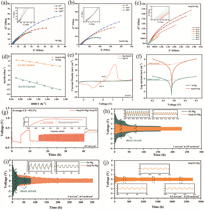
To objectively elucidate their kinetic advantages, electrochemical impedance spectroscopy (EIS) was employed to investigate the ion diffusion process at the interface of the solid electrolyte. Figs. 2a and b present the Nyquist plots of Ni-Mg and Sn@Ni-Mg symmetrical cells after various cycles. The data are fitted to corresponding equivalent circuit models to evaluate Mg2+ transport in the interfacial layer (Fig. S8 in Supporting information). Prior to cycling, the Rs values of both materials are non-zero ohms due to the presence of a gradient electronic insulation layer on Sn@Ni-Mg and a passivation layer on Ni-Mg. Furthermore, the high specific surface area of nickel foam significantly reduces the current density and partially alleviates electrolyte decomposition. As a result, both Ni-Mg and Sn@Ni-Mg initially display low interfacial impedance (RSEI) values of 113 Ω and 1.5 Ω, respectively. The absence of protection provided by an artificial layer and the accumulation of passivation materials lead to a seven-fold increase in RSEI of Ni-Mg after cycling. However, the RSEI of the Sn@Ni-Mg remains almost unchanged even after 400 cycles, indicating fast ionic conductivity and effective prevention of electrolyte decomposition. After 200 cycles, the charge transfer resistance (Rct) of Ni-Mg experiences a significant increase from 8281 Ω to 26,302 Ω, surpassing that of Sn@Ni-Mg, which remains at 1277 Ω. These results further underscore the crucial role of the electronic insulation layer and the fast ion-conducting layer in the cycling of Mg-ion batteries.
Figure 2
Figure 2.
Comparison of the kinetics and electrochemical performance between the Sn@Ni-Mg gradient conductivity anode and the Ni-Mg anode. EIS of (a) Ni-Mg and (b) Sn@Ni-Mg after different cycles. (c) EIS measurement of Sn@Ni-Mg gradient conductivity anode at different temperatures. (d) Arrhenius behavior and activation energies derived from the Nyquist plots of Sn@Ni-Mg and Ni-Mg symmetrical cells. (e) CV curves of Mg//Ni and Mg//Sn@Ni half-cells at a scanning rate of 25 mV/s. (f) Tafel plots derived from liner polarization curves of Sn@Ni-Mg and Ni-Mg symmetric cells. (g) Aurbach measurement of Mg metal CE in the Sn@Ni-Mg//Sn@Ni half-cell. Voltage-time curves of Sn@Ni-Mg and Ni-Mg symmetric cells at current densities of (h) 1 mA/cm2 and (i) 2 mA/cm2, respectively. (j) Long-term galvanostatic cycling of symmetric cell with Sn@Ni-Mg at 0.5 mA/cm2 with a capacity of 0.125 mAh/cm2.
To better understand the unique function of the Sn@Ni-Mg gradient conductivity structure, we conducted an evaluation of the apparent activation energy (Ea) using the Arrhenius formula ln(Rint-1) = lnA – (Ea/RT) [18] (where Rint is the Mg2+ transport impedance at the interface, A is the pre-factor, R is the universal gas constant and T is the absolute temperature), which reflects the desolvation barrier and Mg2+ transport kinetics. Temperature-dependent EIS between 25 ℃ and 55 ℃ was utilized to examine the activation energy required for Mg2+ diffusion through the SEI (Fig. 2c and Fig. S9 in Supporting information). Based on analysis, it is determined that Ea obtained from the slope is 51.5 kJ/mol for the Ni-Mg anode and 28.7 kJ/mol for the Sn@Ni-Mg anode, which can be interpreted as low interfacial activation energy contributing to a low Mg2+ diffusion energy barrier (Fig. 2d). Simultaneously, it demonstrates that the gradient SEI interface can suppress electronic leakage and deteriorating interfacial layers while providing a fast transport channel for Mg2+. Cyclic voltammetry (CV) was performed at a scan rate of 25 mV/s to evaluate the reversibility of Mg plating/stripping process in Mg//Ni and Mg//Sn@Ni half-cells (Fig. 2e). The results demonstrate that Mg//Ni half-cell exhibits a very low response current with a weak oxidation peak near 2 V, reflecting the poor kinetics and irreversible Mg plating and stripping behavior. In contrast, Mg//Sn@Ni exhibits a significant current response and a lower onset reduction (−0.22 V)/oxidation potential (0.12 V). What is more, Mg//Sn@Ni shows a significant current response with a pair of reduction/oxidation peaks representing magnesium plating and stripping at potentials of −1 V and 1.1 V respectively, suggesting a higher kinetic response for the Sn@Ni scaffolds. Additionally, CV curves at a low scan rate were included for more details. Compared to high scan rates, the CV curve of Mg//Sn@Ni exhibits an additional reduction peak emerging at 0.4 V, which corresponds to the alloying process of Mg (Fig. S10 in Supporting information). Owing to abundant exposed active sites and rapid transport channels for Mg2+, Sn@Ni-Mg exhibits significantly higher exchange current density of 0.582 mA/cm2 compared with the value of Ni-Mg (0.000537 mA/cm2) (Fig. 2f and Fig. S11 in Supporting information).
LSV test was conducted on Sn@Ni-Mg//Cu and Ni-Mg//Cu half-cells to assess the stability of the Mg(TFSI)2 electrolyte (Fig. S12 in Supporting information). As illustrated in the figure, the Mg(TFSI)2 electrolyte displays enhanced oxidation stability in Sn@N-Mg//Cu half-cell at 2.86 V in comparison to Ni-Mg//Cu (2.26 V) at a scan rate of 25 mV/s. The effectiveness of the Sn@Ni-Mg gradient conductivity anode was further evaluated by the Aurbach Average Coulombic Efficiency test method (Average CE) [40]. During the stripping process of Mg, when the stripping process of Mg concludes and charging continues, the voltage does not increase but instead decreases, and the voltage curve transitions from a smooth state to irregular fluctuations (Fig. 2g). This behavior suggests the onset of side reactions that hinder the voltage increase. To investigate this condition, the Sn@Ni electrode was disassembled from the Sn@Ni-Mg//Sn@Ni cell in both its normally charged and overcharged states. Surface morphologies were examined, and the composition was performed by XPS analysis. As shown in Fig. S13 (Supporting information), the surface of the over-charge Sn@Ni electrode is coated with dark passivation layers compared with normal-charge Sn@Ni electrode, indicating severe electrolyte decomposition on its surface. Furthermore, XPS results reveal that the F 1s spectrum can be fitted with two peaks at 685.5 and 688.7 eV, representing MgF2 and C-F (from residual Mg(TFSI)₂), respectively [7]. Notably, the MgF2 signal is more pronounced in the over-charge Sn@Ni. Similarly, the Mg 2p and S 2p spectra confirm the presence of SO42-, SO32-, MgO, and MgS, which are products of TFSI- anion decomposition [41,42].However, the normal-charge Sn@Ni contains minor electrolyte decomposition products on its surface. Therefore, the occurrence of voltage curve decline and irregular fluctuations during the charging process can be regarded as an indication of electrolyte decomposition. The plating/stripping of Mg on Sn@Ni-Mg gradient conductivity anode delivers an impressive CE of 93.1%, suggesting excellent reversibility. Instead, Ni-Mg cell suffers a short circuit after 17 cycles and exhibits a mere CE of 41.6%, which could be attributed to the inhomogeneous deposition of Mg (Fig. S14 in Supporting information). Due to the high nucleation barrier of Mg2+ on the non-magnesophilic nickel metal surface, a large amount of Mg metal is not plating on the nickel foam surface, but collects in the separator, resulting in a short circuit with fewer cycles.
To comprehensively assess the cyclic stability of the symmetrical Sn@Ni-Mg and Ni-Mg batteries, long cycles with a constant capacity and long cycles with a constant cycle time were conducted, respectively. Fig. 2h and Fig. S15 (Supporting information) show the constant current cycling curves at current densities of 0.25, 0.5 and 1 mA/cm2 while maintaining a fixed capacity of 0.125 mAh/cm2. During the initial stage of cycling, both Sn@Ni-Mg and Ni-Mg exhibit a process of polarizing voltage drop, known as the activation process. This phenomenon can be elucidated by the presence of inactive species adsorbed on the surface prior to the commencement of Mg plating/stripping, leading to an elevated initial polarizing voltage. After a period of cycling, the electrode becomes activated and the surface inactive materials are consumed, leading to the stabilization of polarization voltage [43]. During cycling, the voltage of the Ni-Mg symmetric cells experiences a rapid drop; however, the time-voltage curve does not show rectangular shapes, a phenomenon referred to as a soft short circuit triggered by the accumulation of Mg deposit in the separator pores [44]. When the time-voltage curves exhibit sudden drops and rectangular shapes with low overpotential, it suggests that a complete short circuit is triggered by Mg dendrite growth inside the Ni-Mg symmetric cell [45]. In comparison, the Sn@Ni-Mg symmetric cells exhibit excellent durability, achieving 1000 stable cycles at current densities of 0.25–1 mA/cm2. Surprisingly, when subjected to more demanding conditions (2 mA/cm2), the hysteresis voltage of the Sn@Ni-Mg symmetric cell increases, yet it still maintains stable Mg plating and stripping, achieving 700 stable cycles without short circuit (Fig. 2i). For practical applications, we also evaluated the cycling performance of Ni-Mg and Sn@Ni-Mg symmetrical batteries at a high areal capacity of 2 mAh/cm2. As illustrated in Fig. S16 (Supporting information), Sn@Ni-Mg exhibits stable Mg plating/stripping behavior and an exceptionally low polarization voltage of 0.4 V at 2 mA/cm2, confirming the excellent durability of the gradient-conductivity SEI layer in the Mg(TFSI)2-DME electrolyte. In contrast, the Ni-Mg symmetrical cells, lacking Mg affinity sites, experience short-circuit after only few cycles due to uneven Mg deposition. Benefiting from the exceptional durability of gradient conductivity artificial SEI, Sn@Ni-Mg symmetric battery achieves an impressively long stable cycle of 2800 h (5300 cycles) under 0.5 mA/cm2 (Fig. 2j).
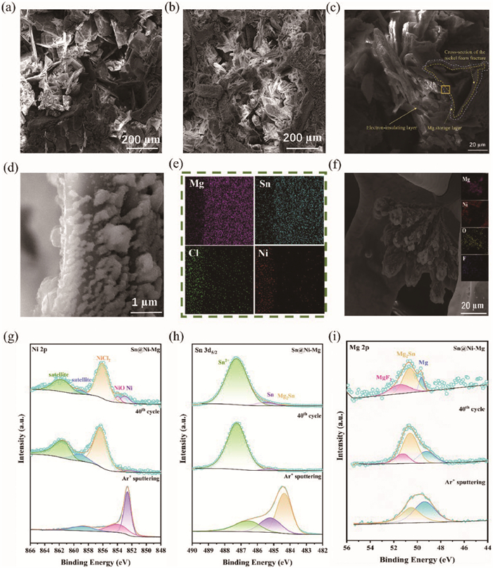
A comprehensive series of characterizations was conducted on Sn@Ni-Mg to investigate the plating performance of Mg on Sn@Ni gradient conductivity scaffolds. After electrochemical plating, the peaks corresponding to the Mg (101) plane (located at 32.1°, 34.4°, 36.6°, 47.8° and 47.1°) and the peaks of Mg2Sn are observed on the surface, consistent with the expected outcomes, indicating the successful plating of Mg on the Sn@Ni gradient conductivity scaffolds and realization of an alloying process (Fig. S17 in Supporting information). SEM was employed for the morphological characterization of the Mg plating and stripping on Sn@Ni-Mg gradient anode. Following the plating and stripping of 5 mAh/cm2 of Mg, the Sn@Ni-Mg gradient conductivity anode retains a stable morphology with cross-distributed electronic insulation laminates still evident on its surface (Figs. 3a and b). EDS elemental distribution mapping of the Sn@Ni-Mg cross-section reveal a uniform and dense distribution of Mg elements within the intermediate layer (Figs. 3c-e). These observations suggest that the electronic insulation provided by surface chlorides, combined with the uniform electron flux facilitated by the Mg2Sn alloy, enables homogeneous internal deposition of Mg. Moreover, it is important to note that the cross-distributed laminates play an essential role in mitigating surface stresses, thereby reducing the volume expansion associated with the alloying process. Consequently, this leads to a good morphology devoid of cracks, ensuring the structural integrity of the Mg storage layer. In comparison, post-plating observations reveal the formation of flower-like deposits on the Ni-Mg surface, which EDS analysis confirms to be Mg dendrites coated with substantial amounts of F and O elements, suggesting electrolyte decomposition leading to highly passivated Mg dendrites (Fig. 3f). After initial nucleation, passivation on the nickel foam electrode causes an uneven electric field distribution, which concentrates the local current density at the nucleation sites. As a result, this non-uniform electric field accelerates the convergence of Mg2+ ions toward the tips of the nucleus, exacerbating uneven deposition and harmful parasitic reactions [46]. Moreover, the passivated material coexists with deposited Mg and cannot be stripped, leading to the irreversible plating/stripping of Ni-Mg. When the flower cluster deposition passes through glass fiber separators, a short circuit is initiated, significantly diminishing the battery’s lifetime.
Figure 3
Figure 3.
SEM and XPS analysis of the Sn@Ni-Mg gradient conductivity anode. Surface view of Sn@Ni-Mg (a) after plating with 5 mAh/cm2 of Mg and (b) stripping with 5 mAh/cm2 of Mg. (c, d) Cross-sectional image for Sn@Ni-Mg plated with 5 mAh/cm2 and (e) the corresponding EDS mapping of Mg, Sn, Cl and Ni, respectively. (f) SEM image of Ni-Mg after plating with 5 mAh/cm2 and correspond EDS analysis. XPS analysis of the (g) Ni 2p, (h) Sn 3d5/2 and (i) Mg 2p spectra for Sn@Ni-Mg (top), after 40 cycles (middle) and 800 s depth Ar ion sputtering (bottom), respectively.
To investigate the stability and compatibility of the anode-electrolyte interface, a detailed analysis of the surface and internal chemical composition of the Sn@Ni-Mg gradient anode before and after cycling was carried out using XPS analysis (Figs. 3g-i). The XPS results show that the surface of the Sn@Ni-Mg anode primarily comprises electronic insulation substances NiCl2 and SnCl2 after Mg deposition. The Mg 2p spectra can be fitted to three peaks at 49.68, 50.65, and 51.49 eV, corresponding to metallic Mg, the alloy product Mg2Sn (located at 484.4 eV in the Sn 3d5/2 spectra) [31], and MgF2 [47], respectively. The lower content indicated by the weak signal in the Mg 2p spectra provides further evidence that Sn@Ni-Mg possesses excellent electronic insulation, preventing electrolyte decomposition and Mg plating on the surface. After 40 cycles, it is observed that the composition of the Sn@Ni-Mg surface remains stable, indicating the good structural stability and durability of the gradient conductive SEI layer. Besides, the signals acquired from XPS depth profiling using Ar+ ions sputtering of cycled Sn@Ni-Mg gradient conductivity anode are utilized to validate the Mg2+ transport pathway (Fig. S18 in Supporting information). As the sputtering depth increases, there is a gradual decrease in Sn2+ content and a corresponding increase in Mg2Sn content. The Mg 2p spectra reveal a progressive decline in Mg2Sn content and a simultaneous increase in metallic Mg proportion, indicating that Mg2+ diffuses towards the bottom of the Sn@Ni-Mg gradient conductivity anode, forming a predominantly Mg-dominated interface at the bottom. In contrast, the Ni-Mg anode without a gradient conductivity SEI exhibits a significantly higher percentage of surface passivation components, MgF2 and MgO (located at 50.4 eV in the Mg 2p spectra), compared to Sn@Ni-Mg under the same conditions (Fig. S19 in Supporting information). Additionally, due to the strong passivation of the Ni-Mg surface, the total amount of internal Mg after sputtering is only 50 at%. These XPS findings are in strong agreement with the anticipated Sn@Ni-Mg structure. The Sn@Ni-Mg gradient conductivity anode comprises an electronic insulation layer with NiCl2 and SnCl2, along with an intermediate electron-ion conducting layer composed of metallic Sn and Mg2Sn. Meanwhile, the XPS analysis results also confirm the excellent electronic insulation properties of NiCl2 and SnCl2, which effectively inhibit Mg deposition on the surface and reduce interface passivation. The migration and deposition of Mg2+ to the bottom of Sn@Ni-Mg effectively prevent direct contact between deposited Mg and the electrolyte, thereby suppressing the formation of "dead Mg". In summary, the excellent component stability and gradient conductivity design of Sn@Ni-Mg ensure the reversible Mg plating and stripping.
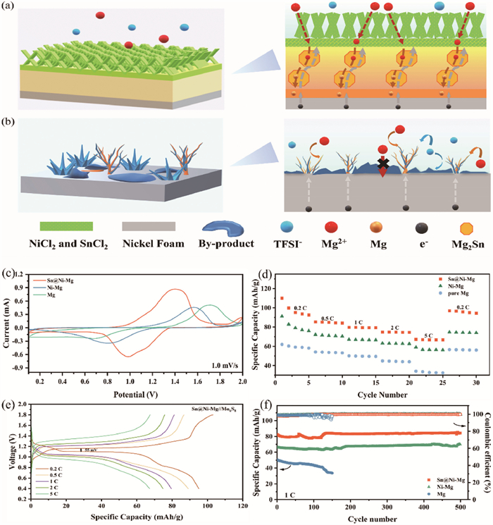
Following characterization and analysis, the deposition behavior of Mg on Sn@Ni-Mg 3D gradient conductivity anode and nickel foam is illustrated. The laminates on the Sn@Ni surface, comprised of NiCl2 and SnCl2, exhibit abundant vacancies and self-adsorbed atoms that significantly enhance the propensity for Mg deposition in these regions [48]. Moreover, the NiCl2 and SnCl2 coupled with their electronic shielding characteristics, effectively impede Mg2+ from acquiring electrons at the surface to undergo reduction to metallic Mg. Consequently, this prevents the deposition of electrolyte decomposition products plating on the Mg metal surface, inhibiting passivation due to surface electronic insulation layer. After traversing the ion-conductive-preferred electronic insulation layer, Mg2+ reach the rapid conduction layer of Mg2Sn, which exhibits metallic-level electronic conductivity [49]. This ensures a continuous and uniform electric field, leading to the uniform transmission of Mg2+. Chai et al. utilized density functional theory (DFT) to calculate the diffusion and migration barriers of Mg in alloy layer, comparing the Mg affinity of metallic Sn and the Mg-Sn alloy. It was found that Mg exhibits a low migration barrier of 0.30 eV in Mg2Sn, facilitating rapid Mg2+ migration. Additionally, the adsorption energies of Mg atoms on Sn and Mg2Sn surfaces are −1.53 eV and −1.40 eV, respectively, which are better than Mg metal (−0.76 eV). Lower adsorption energies indicate a stronger affinity for Mg, allowing the magnesiophilic Sn sites to preferentially adsorb Mg atoms, thereby significantly reducing the Mg nucleation barrier [50]. Furthermore, nickel foam, characterized by its high specific surface area, can mitigate the local electric field intensity even under high-voltage conditions, ensuring the uniform transport of Mg2+ ions and ultimately achieving uniform Mg deposition (Fig. 4a) [51].
Figure 4
Figure 4.
Schematic illustration of Mg deposition on (a) Sn@Ni-Mg gradient conductivity scaffolds and (b) nickel foam, respectively. Electrochemical performances of full cells. (c) Cyclic voltammograms with a scan rate of 1.0 mV/s. (d) Rate performances of Sn@Ni-Mg//Mo6S8, Ni-Mg//Mo6S8 and Mg//Mo6S8. (e) Galvanostatic charge–discharge profiles of Sn@Ni-Mg//Mo6S8 at different rates. (f) Cycling stabilities of Sn@Ni-Mg//Mo6S8, Ni-Mg//Mo6S8 and Mg//Mo6S8 at 1 C.
Taken together, the requirements (non-passivation, consistent electron/ion fluxes, and rapid Mg2+ diffusion) can be satisfied to ensure the extended use of Mg metal anodes in conventional electrolytes through the synergistic effect of the gradient conductivity SEI and the high specific surface area metal scaffolds of Sn@Ni-Mg. Despite the low surface self-diffusion barrier of Mg, achieving uniform Mg plating on a metal network scaffold with high specific surface area alone is insufficient under a high-voltage electric field. Nickel foam, as a non-magnesiophilic metal, lacks nucleation sites, leading to uneven charge distribution and irregular Mg2+ flux, which in turn cause local Mg deposition [52]. Furthermore, if the applied electric current surpasses a specific limit, it will promote reaction rates and reduce self-diffusion barriers, which in turn facilitate the growth of Mg at the tip and result in cluster dendrites [53]. Concurrently, violent decomposition of the electrolyte causes severe passivation on the Ni-Mg surface, leading to irreversible cycles (Fig. 4b) [54,55].
To reveal the practical application potential of the obtained anode, full cells were constructed by combining the Sn@Ni-Mg, Ni-Mg and pure Mg anodes with Chevrel phase Mo6S8 cathodes. The XRD pattern of the anode material is shown in Fig. S20 (Supporting information), indicating that we successfully synthesized Chevrel phase Mo6S8 by high temperature solid phase method [56]. In the CV curves (Fig. 4c), the full cells composed of Mo6S8 exhibit a pair of redox peaks at a sweep rate of 1.0 mV/s, which correspond to the deintercalation and intercalation of Mg2+, respectively. It is evident that Sn@Ni-Mg//Mo6S8 full cell displays higher electrochemical activity and lower polarization voltage in comparison to Mg and Ni-Mg, indicating the gradient conductivity SEI layer plays a role in the transport kinetics of Mg2+. Fig. 4d illustrates the rate performance of the full cells from 0.2 C to 5 C (1 C = 128 mA/g), demonstrating notable discrepancies in specific capacity between the three full cells. Specifically, both Ni-Mg and Sn@Ni-Mg full cells with a three-dimensional network skeleton exhibit higher specific capacities at different current densities compared to pure Mg. At current densities up to 5 C, the Sn@Ni-Mg//Mo6S8 exhibits an impressive specific capacity of 67.3 mAh/g, which is significantly higher than that of Ni-Mg and pure Mg (56.4 and 32.8 mAh/g, respectively). Further analysis of the first charge/discharge curves at different rates of the three showed that the Ni-Mg//Mo6S8 and Mg//Mo6S8 full cells charge/discharge curves exhibited a larger voltage polarization compared to Sn@Ni-Mg//Mo6S8 (55 mV for Sn@Ni-Mg, 150 mV for Ni-Mg, and 470 mV for pure Mg at 0.2 C) (Fig. 4e, Figs. S21a and b in Supporting information). This observation indicates the superior reaction kinetics and rate performance of the Sn@Ni-Mg//Mo6S8 cells. Concurrently, the discrepancy in polarization voltage impacts the capacity retention of the full cell during long cycling. As illustrated in Fig. 4d, the Sn@Ni-Mg//Mo6S8 full cell displays enhanced cycling stability, exhibiting a capacity retention of 95.6% (84.2 mAh/g) after 500 cycles at 1 C. In contrast, the inevitable passivation of pure Mg results in Mg//Mo6S8 cells significant capacity decay and eventually failed, with a capacity retention of only 66.8% (33.7 mAh/g). Furthermore, at a higher rate of 5 C, Sn@Ni-Mg//Mo6S8 full cell also exhibits higher specific capacity over 70 mAh/g and superior stability within 1000 cycles (Fig. S21c in Supporting information). It is noteworthy that the discharge specific capacity of Ni-Mg//Mo6S8 full cell exhibits greatly variability during cycling. This observation can be attributed to the potential influence of water molecules present in the electrolyte on the surface structure of Ni-Mg, which in turn affects the plating and stripping of Mg2+, resulting in significant fluctuations in the cycling performance [15,57]. In contrast, Sn@Ni-Mg ensures normal Mg2+ transport due to the presence of the surface SEI layer, significantly reducing the influence of water molecules on the anode and ultimately achieving stable cycling. Finally, at a current density of 25.6 mA/g and based on the cathode material Mo6S8, we calculated the mass energy densities of Sn@Ni-Mg and Ni-Mg to be 96.05 Wh/kg and 73.05 Wh/kg, respectively. It is proved that the combination of surface gradient conductivity SEI and 3D scaffolds has a great prospect in practical applications in RMBs.
In summary, we have successfully fabricated 3D gradient conductivity scaffolds using nickel foam via a simple displacement reaction. Subsequently, Mg was electrochemically plated onto the gradient conductivity scaffolds to create the Sn@Ni-Mg 3D gradient conductivity anode. Combined with SEM and XPS analysis, we have elucidated the deposition behavior of Mg on the Sn@Ni, and thoroughly analyzed the role of each component in the gradient SEI was analyzed. The electronic insulation chlorides impede the deposition of Mg on the surface, while the Sn-based composite intermediate layer facilitates fast transmission of Mg2+ and a uniform electron flux. Additionally, the bottom nickel foam network scaffolds effectively disperse local high-voltage electric fields. These modifications significantly enhance diffusion kinetics and address the issue related to uneven Mg deposition caused by local high current density. The composition of the gradient SEI in the Sn@Ni-Mg anode remains invariant during cycling and the symmetrical battery achieves over 2800 h (5300 cycles) of continuous charge-discharge cycling at a current density of 0.5 mA/cm2. When coupled with Mo6S8 cathodes, the full cell shows remarkable rate performance and cycling stability, with 95.6% capacity retained and 99% Coulombic efficiency at 1 C. The methodology proposed in this paper-combining a dispersive current density strategy with a gradient conductivity electrode-promotes practical applications for Mg metal batteries and paves the way for designing reversible Mg metal anodes in non-corrosive traditional electrolytes.
Declaration of competing interest
The authors declare that they have no known competing financial interests or personal relationships that could have appeared to influence the work reported in this paper.
The authors appreciate the support from National Natural Science Foundation of China (Nos. 52301282, 52072256), Key R & D program of Shanxi Province (Nos. 202102030201006, 202202070301016), Central Guide Local Science and Technology Development Funding Program (No. YDZJSX2021B005), Shanxi Province Science and Technology Program Unveiled Bidding Program (No. 20201101016), Science and Technology Innovation Base Construction Project of Shanxi Province (No. YDZJSX2022B003), Fundamental Research Program of Shanxi Province (No. 20210302124308), Shanxi Province Fundamental Research Program Youth Program (Nos. 202303021212044, 202303021212047), Teaching Reform Project of Shanxi Province (No. 2021YJJG046).
Supplementary materials
Supplementary material associated with this article can be found, in the online version, at doi:10.1016/j.cclet.2025.111080.
[1]
Y. Liang, H. Dong, D. Aurbach, et al., Nature Energy 5 (2020) 646–656. doi: 10.1038/s41560-020-0655-0
[2]
J. Muldoon, C.B. Bucur, T. Gregory, Chem. Rev. 114 (2014) 11683–11720. doi: 10.1021/cr500049y
[3]
C. Zhang, A. Wang, L. Guo, et al., Angew. Chem. Int. Ed. 61 (2022) e202200181. doi: 10.1002/anie.202200181
[4]
L. Guo, A. Chen, A. Wang, et al., J. Am. Chem. Soc. 146 (2024) 26855–26862. doi: 10.1021/jacs.4c07707
[5]
J. Zhang, Z. Chang, Z. Zhang, et al., ACS Nano 15 (2021) 15594–15624. doi: 10.1021/acsnano.1c06530
S. DeWitt, N. Hahn, K. Zavadil, et al., J. Electrochem. Soc. 163 (2016) A513. doi: 10.1149/2.0781603jes
[56]
Y. Du, Y. Chen, S. Tan, et al., Energy Storage Mater. 62 (2023) 102939.
[57]
Y. Liu, W. Zhao, Z. Pan, et al., Angew. Chem. Int. Ed. 62 (2023) e202302617.
Figure 1
Schematic of gradient conductivity scaffolds Sn@Ni. (a) Preparation mechanism of Sn@Ni. (b) Surface SEM images of Sn@Ni (Insert: photo of Sn@Ni). (c) Enlarged SEM images and corresponding EDS analysis of Sn@Ni. (d) XRD patterns of nickel foam and Sn@Ni. (e) Ni 2p spectra and Sn 3d5/2 spectra of Sn@Ni (top), and after 200 s Ar+ sputtering (bottom), respectively. (f) Voltage profile of galvanostatic deposition of Sn@Ni//Mg and Ni//Mg cells at 500 μA/cm2. (g) Galvanostatic cycling performances of Ni-Mg and Sn@Ni-Mg anodes under different current densities (from 10 µA/cm2 to 2000 μA/cm2).
Figure 2
Comparison of the kinetics and electrochemical performance between the Sn@Ni-Mg gradient conductivity anode and the Ni-Mg anode. EIS of (a) Ni-Mg and (b) Sn@Ni-Mg after different cycles. (c) EIS measurement of Sn@Ni-Mg gradient conductivity anode at different temperatures. (d) Arrhenius behavior and activation energies derived from the Nyquist plots of Sn@Ni-Mg and Ni-Mg symmetrical cells. (e) CV curves of Mg//Ni and Mg//Sn@Ni half-cells at a scanning rate of 25 mV/s. (f) Tafel plots derived from liner polarization curves of Sn@Ni-Mg and Ni-Mg symmetric cells. (g) Aurbach measurement of Mg metal CE in the Sn@Ni-Mg//Sn@Ni half-cell. Voltage-time curves of Sn@Ni-Mg and Ni-Mg symmetric cells at current densities of (h) 1 mA/cm2 and (i) 2 mA/cm2, respectively. (j) Long-term galvanostatic cycling of symmetric cell with Sn@Ni-Mg at 0.5 mA/cm2 with a capacity of 0.125 mAh/cm2.
Figure 3
SEM and XPS analysis of the Sn@Ni-Mg gradient conductivity anode. Surface view of Sn@Ni-Mg (a) after plating with 5 mAh/cm2 of Mg and (b) stripping with 5 mAh/cm2 of Mg. (c, d) Cross-sectional image for Sn@Ni-Mg plated with 5 mAh/cm2 and (e) the corresponding EDS mapping of Mg, Sn, Cl and Ni, respectively. (f) SEM image of Ni-Mg after plating with 5 mAh/cm2 and correspond EDS analysis. XPS analysis of the (g) Ni 2p, (h) Sn 3d5/2 and (i) Mg 2p spectra for Sn@Ni-Mg (top), after 40 cycles (middle) and 800 s depth Ar ion sputtering (bottom), respectively.
Figure 4
Schematic illustration of Mg deposition on (a) Sn@Ni-Mg gradient conductivity scaffolds and (b) nickel foam, respectively. Electrochemical performances of full cells. (c) Cyclic voltammograms with a scan rate of 1.0 mV/s. (d) Rate performances of Sn@Ni-Mg//Mo6S8, Ni-Mg//Mo6S8 and Mg//Mo6S8. (e) Galvanostatic charge–discharge profiles of Sn@Ni-Mg//Mo6S8 at different rates. (f) Cycling stabilities of Sn@Ni-Mg//Mo6S8, Ni-Mg//Mo6S8 and Mg//Mo6S8 at 1 C.

 DownLoad:

 下载:
下载:


 下载:
下载:
