Received Date:
04 December 2024 Accepted Date:
05 March 2025 Revised Date:
24 February 2025 Available Online:
15 July 2026
Abstract:
The design and exploitation of high-property cathode materials and the exploration of their energy storage mechanism have always been research hotspots in the area of zinc-ion hybrid capacitors (ZHCs). In this study, the new RuO2 nanodots/reduced graphene oxide (RuO2 NDs/rGO) composite is designed, and employed as a cathode for ZHC for the first time. Thanks to the synergism of nanoscale design and composite engineering, the RuO2 NDs/rGO//Zn ZHC delivers large specific capacitance (169.5 mAh/g at 0.1 A/g), splendid rate property (74.4 mAh/g at 20 A/g), eminent cyclic property (up to 10,000 cycles), and high energy and power densities (101.7 Wh/kg and 12 kW/kg). Furthermore, systematic kinetic analyses are used to confirm the rapid ion transport kinetics of the RuO2 NDs/rGO//Zn ZHC. More importantly, systematic ex-situ measurements are employed to illustrate its energy storage mechanism of the coexistence of electric double-layer capacitance (physical adsorption/desorption of SO42-) and pseudocapacitance (insertion/extraction of Zn2+ and H+ and chemical adsorption/desorption between Zn2+ and oxygen-containing functional groups). This study not only offers a good strategy for the design and exploitation of high-performance pseudocapacitive cathode for ZHCs, but also proposes an insight into energy storage mechanism of RuO2-based pseudocapacitive cathode.
Recently, with the rapid development of consumer electronics, electric vehicles, and new energy systems, the requirement for high-property energy storage equipment has shown explosive growth [1,2]. Among them, Li-ion batteries (LIBs) have become the most extensively utilized commercial energy storage systems on account of their high energy density and high energy efficiency. However, the scarcity of lithium resources and safety problems have severely limited their further exploitation and application [3,4]. Among the new energy storage systems, aqueous Zn-ion hybrid capacitors (ZHCs) have drawn extensive concern from researchers owing to their large theoretical capacity (820 mAh/g), splendid stability, and low redox potential (−0.76 V vs. SHE) [5,6]. Unfortunately, the relatively small energy density of ZHCs impedes their practical applications. Generally, the zinc anodes have high theoretical specific capacitance, while the capacitive cathode materials have lower specific capacitance. According to the short-board effect, the design and development of high-capacitance cathode materials are crucial for boosting the energy density of ZHCs.
Carbon-based capacitive cathode materials, including porous carbon [7,8], activated carbon [9], carbon nanotubes [10], metal organic framework (MOF) derived carbon [11-13], and graphene [14-16], have been widely applied in ZHCs. Among them, researchers have modified carbon-based materials through strategies such as structural design and surface modification, which significantly improve their specific surface area, electronic conductivity and electrochemical reactivity, shorten their ion transport paths, and effectively improve their electrochemical performance [17,18]. However, the ZHCs with carbon-based cathode [19] still exhibit limited energy density arising from the energy storage process dominated by the electric double-layer (EDL) capacitance. In view of this, the exploitation of pseudocapacitive cathode materials with large theoretical specific capacitance is a good strategy to further boost the energy density of ZHCs.
Various typical pseudocapacitive cathode materials, including MXenes [20,21], conductive polymers [22], and transition metal oxides [23], exhibit higher theoretical specific capacitance due to their unique Faradaic reaction mechanisms. These materials are able to undergo reversible redox reactions with zinc ions, thereby storing more charge and enhancing the energy density of ZHCs. Among various pseudocapacitive cathode materials, RuO2, especially hydrated amorphous RuO2, is regarded as an ideal energy storage material due to its large theoretical specific capacitance, splendid stability, and highly reversible electrochemical oxidation/reduction characteristics compared with other cathode materials [23]. Unfortunately, the insufficient electrochemical reaction between RuO2 and the electrolyte results in limited specific capacitance, as well as poor rate performance and cyclic lifespan. The RuO2 nanomaterials have been proved to have the characteristics of small particle size and high surface/volume ratio, which can sufficiently improve the utilization of electrode materials and enhance their electrochemical redox behavior [24]. However, the high surface energy of nanomaterials can cause severe agglomeration, resulting in the inhomogeneity and densification of morphology and structure, thereby seriously affecting their electrochemical performance. The combination of RuO2 nanomaterials and reduced graphene oxide (rGO) is a feasible method to prevent their agglomeration [25]. The introduction of rGO can reduce the proportion of RuO2 in the composite, consequently decreasing its cost. Moreover, rGO has excellent electronic conductivity and can be used as a conductive matrix to boost the conductivity and electrochemical reactivity of RuO2, thus boosting the overall electrochemical performance of the composite. Therefore, the construction of RuO2 nanodots (NDs)/rGO composite is a feasible strategy to achieve efficient energy storage of ZHCs. As we know, there is no study on the application of RuO2 NDs/rGO in ZHCs, and its energy storage mechanism of RuO2-based pseudocapacitive cathode materials in ZHCs has not been reported yet. Therefore, it is highly significant to study the electrochemical behavior and energy storage mechanism of the RuO2 NDs/rGO cathode in ZHCs.
In this work, the new RuO2 NDs/rGO composite was prepared through sol-gel method combined with low-temperature anneal treatment, and utilized as a cathode for ZHC for the first time. Thanks to the synergism of nanoscale design and composite engineering, the assembled RuO2 NDs/rGO//Zn ZHCs based on the RuO2 NDs/rGO cathode exhibits large specific capacitance (169.5 mAh/g at 0.1 A/g), superior rate property (74.4 mAh/g at 20 A/g), remarkable cyclic performance (90.4% capacity retention after 10,000 cycles at 5 A/g), large energy and power densities (101.7 Wh/kg at 60 W/kg and 41.7 Wh/kg at 12 kW/kg). More impressively, the energy storage mechanism of the EDL and pseudocapacitive reactions of electrolyte ions in the RuO2 NDs/rGO cathode was elucidated for the first time through electrochemical kinetic analyses based on kinetic analyses (cyclic voltammetry (CV) and electrochemical impedance spectroscopy (EIS)) and systematic ex-situ tests (X-ray diffraction (XRD), field emission scanning electron microscopy (FESEM) and corresponding energy-dispersive X-ray spectroscopy (EDS), EIS, and X-ray photoelectron spectroscopy (XPS)). This research not only affords a good strategy for the design and development of ZHCs pseudocapacitive cathode, but also elucidates the energy storage mechanism of the RuO2 NDs/rGO cathode for the first time.
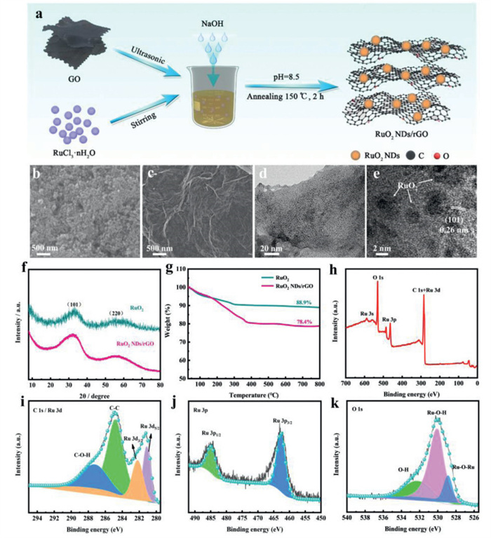
The synthesis process of the RuO2 NDs/rGO composite is presented in Fig. 1a. The RuO2 NDs/rGO composite was prepared by sol-gel method combined with low-temperature calcination treatment using RuCl3·nH2O and GO as precursors. The morphology, microstructure and elemental composition and distribution of the prepared RuO2 NDs/rGO composite were evaluated by FESEM, (high-resolution) transmission electron microscopy (TEM/HRTEM) and elemental mapping tests. As presented in the FESEM images, compared with the agglomerated pure RuO2 (Fig. 1b and Fig. S1 in Supporting information), the RuO2 NDs/rGO composite presents a rGO sheet structure with some folds and the presence of uniformly distributed RuO2 nanodots on the rGO sheet structure (Fig. 1c and Fig. S2 in Supporting information). By the further TEM test (Fig. 1d), it is observable that the RuO2 nanodots are even distributed on the rGO sheets with a size of 5–8 nm. As presented in the HRTEM image (Fig. 1e), a lattice spacing of 0.26 nm can be observed, belonging to the (101) crystal plane of RuO2, which is consistent with XRD analysis results [26]. Moreover, the co-presence and uniform distribution of Ru, O, and C elements in the RuO2 NDs/rGO composite are clearly observed in the elemental mapping test, as demonstrated in Fig. S3 (Supporting information). Besides, N2 adsorption-desorption test (Fig. S4 in Supporting information) reveals that the RuO2 NDs/rGO composite possesses a high BET surface area of 54.9 m2/g and abundant mesopores in the range of 2.7–4.2 nm, which is conducive to zinc storage and fast ion transport.
Figure 1
Figure 1.
(a) Schematic diagram of the synthesis process of the RuO2 NDs/rGO composite. FESEM images of the (b) pure RuO2 and (c) RuO2 NDs/rGO composite. (d) TEM and (e) HRTEM images of the RuO2 NDs/rGO composite. (f) XRD patterns and (g) TG curves of the pure RuO2 and RuO2 NDs/rGO composite. (h) XPS full spectrum and high-resolution (i) C 1s/Ru 3d, (j) Ru 3p, and (k) O 1s XPS spectra of the RuO2 NDs/rGO composite.
In addition, the structure of the pure RuO2 and RuO2 NDs/rGO composite was examined by XRD test. As shown in Fig. 1f, it is clear that no strong characteristic peaks of RuO2 crystal planes are observed, and two weak and broad diffraction peaks emerge at 2θ = 32.9° and 56.2°, corresponding to the (101) and (220) planes of RuO2, respectively, which indicates that the RuO2 formed during the low-temperature annealing at 150 ℃ is typically amorphous [27,28]. The TG curves of the pure RuO2 and RuO2 NDs/rGO composite are shown in Fig. 1g, from which the mass percentage of rGO in the RuO2 NDs/rGO composite is calculated to be approximately 10 wt%. In order to further investigate the elemental composition and chemical valence of the RuO2 NDs/rGO composite, XPS test was executed. As manifested in Fig. 1h, the survey spectrum of the RuO2 NDs/rGO composite confirms the existence of Ru, O, and C elements. In the high-resolution C 1s/Ru 3d spectrum (Fig. 1i), the peaks situated at 287.2, 284.8, 282.2, and 281.1 eV are indexed to the C—O-H, C—C, Ru 3d3/2, and Ru 3d5/2 [29,30], respectively, and the peak position of Ru 3d5/2 indicates the existence of Ru4+, further verifying the successful preparation of RuO2 [31]. Additionally, in the high-resolution Ru 3p spectrum (Fig. 1j), the main peaks situated at 484.8 and 462.6 eV match with Ru 3p1/2 and Ru 3p3/2, respectively, which belong to ruthenium (Ⅳ) oxide [26]. The high-resolution O 1s spectrum (Fig. 1k) shows three characteristic peaks at 532.1, 530.0, and 528.8 eV, which are relevant to bound water, Ru-O-H, and Ru-O-Ru, respectively [32,33].
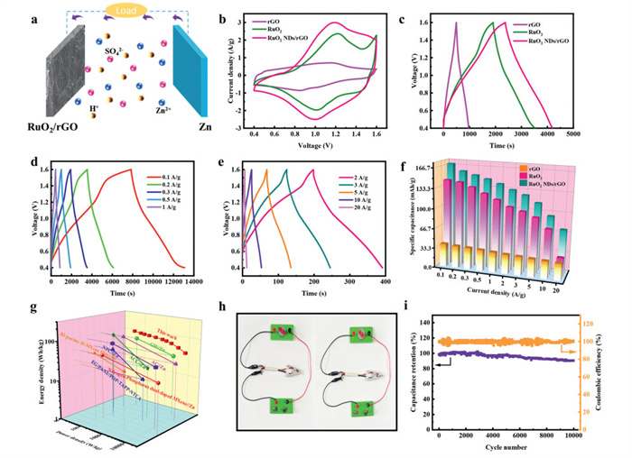
The ZHC (denoted as rGO//Zn, RuO2//Zn and RuO2 NDs/rGO//Zn ZHC) was constructed utilizing Zn foil as the anode, rGO, RuO2 and RuO2 NDs/rGO as the cathode, and 2 mol/L ZnSO4 solution as the electrolyte (Fig. 2a). Fig. S5 (Supporting information) displays the CV profiles of the RuO2 NDs/rGO//Zn ZHC at different voltages, indicating that they can operate stably in the voltage range of 0.4–1.6 V. Figs. 2b and c compare the CV profiles (5 mV/s) and GCD profiles (0.3 A/g) of the rGO//Zn, RuO2//Zn and RuO2 NDs/rGO//Zn ZHCs. Compared with rGO//Zn and RuO2//Zn ZHC, the RuO2 NDs/rGO ZHC presents larger CV curve area and higher reversible specific capacity. As presented in Figs. 2d and e and Fig. S6 (Supporting information), all GCD curves are approximately symmetric at current densities of 0.1–20 A/g, indicating that the ZHCs have good capacitive behavior. The specific capacities of the RuO2 NDs/rGO//Zn ZHC at current densities of 0.1, 0.2, 0.3, 0.5, 1, 2, 3, 5, 10, and 20 A/g are 169.5, 158.5, 153.2, 147.9, 141.4, 133.0, 126.1, 114.7, 95.0, and 74.4 mAh/g, respectively, exhibiting larger specific capacity and better rate performance compared to rGO//Zn and RuO2//Zn ZHC (Fig. 2f), which is ascribed to the synergism of nanoscale design and composite engineering on the RuO2 cathode [34]. It is worth noting that the RuO2 NDs/rGO//Zn ZHC exhibits an energy density of 101.7 Wh/kg @60 W/kg based on the RuO2 NDs/rGO cathode, and still retains an energy density of 44.7 Wh/kg even at 12 kW/kg, outperforming most of previously reported ZHCs such as GH//Zn (76.2 Wh/kg @147.6 W/kg, 39 Wh/kg @6.54 kW/kg) [35], AC//Zn (84 Wh/kg @66.6 W/kg, 30 Wh/kg @14.9 kW/kg) [9], ACC//Zn (100 Wh/kg @43.9 W/kg, 20.4 Wh/kg @1.69 kW/kg) [36], EG/PANI//POP-TAPP-NTCA (48 Wh/kg @85 W/kg, 12 Wh/kg @2.01 kW/kg) [37], NPC//Zn (82 Wh/kg @167.7 W/kg, 35 Wh/kg @12.5 kW/kg) [38], N, P-MXene//Zn (43.9 Wh/kg @117 W/kg, 19 Wh/kg @29 kW/kg) [39], and H-MXene//Zn (53.6 Wh/kg @110 W/kg, 28 Wh/kg @2.3 kW/kg) [40], as presented in Fig. 2g. Fig. 2h exhibits a small fan powered by two RuO2 NDs/rGO//Zn ZHCs in series, confirming their potential practical application, which further indicates their superior energy storage property. In addition, the cycling performance of the RuO2 NDs/rGO//Zn ZHC was tested at 5 A/g (Fig. 2i). The capacity retention of the RuO2 NDs/rGO//Zn ZHC reaches up to 90.4% after 10, 000 charge-discharge cycles, and its coulombic efficiency approaches 100% during the cycling process, demonstrating its remarkable cycling stability and reversibility.
Figure 2
Figure 2.
(a) Configuration of the RuO2 NDs/rGO//Zn ZHC. (b) CV profiles at 5 mV/s and (c) GCD profiles at 0.3 A/g of the rGO//Zn, RuO2//Zn and RuO2 NDs/rGO//Zn ZHCs. (d, e) GCD profiles at various current densities of the RuO2 NDs/rGO//Zn ZHC. (f) Rate capability of the rGO//Zn, RuO2//Zn and RuO2 NDs/rGO//Zn ZHCs. (g) Ragone plot of the RuO2 NDs/rGO//Zn ZHC in contrast with other ZHCs. (h) Digital images of a small fan driven by two ZHCs. (i) Cycle property and Coulombic efficiency of the RuO2 NDs/rGO//Zn ZHC after 10,000 cycles at 5 A/g.
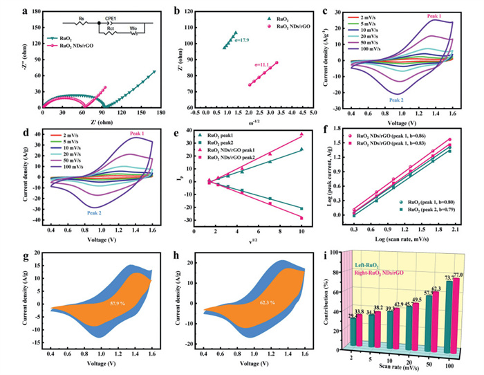
The electrochemical kinetic performance of the RuO2//Zn and RuO2 NDs/rGO//Zn ZHCs was compared by EIS and CV tests. As exhibited in the EIS spectra (Fig. 3a), the RuO2 NDs/rGO//Zn ZHC presents a smaller internal resistance (Rs, 0.84 Ω) and charge transfer resistance (Rct, 63.9 Ω) than the RuO2 electrode by fitting the equivalent circuit diagram, confirming its faster charge transfer kinetics. Meanwhile, Fig. 3b presents the linear fitting diagram of Z' vs. ω−1/2 in the low-frequency region, and the fitted Warburg coefficients (σ) are 11.1 (the RuO2 NDs/rGO//Zn ZHC) and 17.9 (the RuO2//Zn ZHC), respectively. Based on this, the calculated diffusion coefficient of the RuO2 NDs/rGO//Zn ZHC (4.36 × 10⁻¹² cm2/s) is higher than that of the RuO2//Zn ZHC (1.68 × 10⁻¹² cm2/s), which exhibits the same level of ion diffusion capability as supercapacitors, confirming its excellent ion diffusion kinetics [41]. Figs. 3c and d show the CV profiles of the RuO2//Zn and RuO2 NDs/rGO//Zn ZHCs in the voltage range of 0.4–1.6 V at sweep rates varying from 2 mV/s to 100 mV/s, and a pair of wider redox peaks in the CV profiles are clearly observed. It is noteworthy that the redox peaks still exist at a high sweep rate of 100 mV/s, implying that the RuO2 NDs/rGO//Zn ZHC has a good rate property. Furthermore, the electrolyte ion diffusion coefficient can be obtained by fitting the linear relationship between the peak current (Ip) and the sweep rate (v1/2) [42-44], as manifested in Fig. 3e. The calculated ion diffusion coefficient of the oxidation and reduction peaks is 7.58 × 10⁻¹² and 4.51 × 10⁻¹² cm2/s, respectively, which is consistent with the EIS kinetic analysis, further confirming the excellent ion diffusion kinetics of the RuO2 NDs/rGO//Zn ZHC. Furthermore, the excellent electrochemical reaction kinetics of the RuO2 NDs/rGO//Zn ZHC was further elucidated by a semi-qualitative analysis of the linear relationship between the peak current (Ip) and the sweep rate (v) [42-44]. As demonstrated in Fig. 3f, the fitted b-value of the oxidation and reduction peaks of the RuO2 NDs/rGO//Zn ZHC is 0.86 and 0.83, respectively, which is higher than that of the RuO2 electrode (0.80 and 0.79), indicating the more surface capacitive behavior and better electrochemical kinetics. Moreover, as shown in Figs. 3g-i, the RuO2 NDs/rGO//Zn ZHC exhibits higher capacitive contributions at various scan rates compared with the RuO2 electrode, indicating the faster electrochemical kinetics and enhanced rate capability of the RuO2 NDs/rGO electrode.
Figure 3
Figure 3.
(a) EIS plot, (b) linear fitting of Z' vs. ω-1/2 plot in the low-frequency region, (c, d) CV curves at various sweep rates, (e) the linear relationship between Ip and v1/2, (f) LogIpvs. logv plots, (g, h) capacitive contribution at 20 mV/s and (i) capacitive contribution ratio at diverse sweep rates of the RuO2//Zn and RuO2 NDs/rGO//Zn ZHCs.
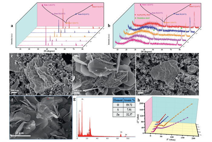
To explore the charge storage mechanism of the RuO2 NDs/rGO//Zn ZHC, various ex-situ tests (XRD, FESEM, EIS, and XPS) were executed on the RuO2 NDs/rGO cathode and Zn anode at diverse states during the charge-discharge process. As manifested in Fig. 4a, the RuO2 NDs/rGO//Zn ZHC was first charged to 1.6 V (State A), and subsequently discharged to 1.0 V (State B) and 0.4 V (State C), followed by recharging to 1.0 V (State D) and 1.6 V (State E). During the charging and discharging process, the ex-situ XRD patterns of the Zn anode show no additional diffraction peaks of other substances, except for variations in the intensity of a few diffraction peaks, indicating that only the electrochemical reaction of Zn2+ deposition/stripping occurs on the anode. For the ex-situ XRD patterns of the cathode (Fig. 4b), it is observable that the main peak position of the RuO2 NDs/rGO cathode does not change significantly during the electrochemical reaction, which indicates that the energy storage of the cathode is attributed to the insertion/extraction (or adsorption/desorption) of electrolyte ions. Meanwhile, it is observable that Zn4SO4(OH)6·4H2O (PDF #44–0673) is formed during the charge/discharge process [45]. The intensity of its characteristic peaks reaches its maximum at fully discharged state (State C), and subsequently disappears after recharging back to State E (1.6 V), suggesting a reversible precipitation/dissolution process. Furthermore, the formation and dissolution of sheet-like substances during the charging/discharging process are also directly observed by ex-situ FESEM images (Figs. 4c-e), and the corresponding EDS (Figs. 4f and g) test reveals that the ratio of Zn and S elements in this product is about 4:1, which further confirms the generation of Zn4SO4(OH)6·4H2O. It is worth noting that the generation of Zn4SO4(OH)6·4H2O contributes less to the energy storage, and its formation is mainly related to the change of H+/OH- on the surface of the RuO2 NDs/rGO cathode [46], implying that H+ or OH- is also involved in the reaction process besides the adsorption/desorption of SO42- on the cathode contributing to the EDL capacitance. In addition, as shown in Fig. 4h, the ex-situ EIS test indicates that Rct gradually increases during the discharge process and decreases during the subsequent charge process, further confirming the reversibility of the precipitation/dissolution process of Zn4SO4(OH)6·4H2O.
Figure 4
Figure 4.Ex-situ XRD patterns of the (a) Zn anode and (b) RuO2 NDs/rGO cathode at various states and corresponding GCD curves at 1 A/g, (c-e) ex-situ FESEM images at different states, (f) ex-situ FESEM image at fully discharged state and (g) corresponding EDS spectrum, and (h) EIS plots at different states of the RuO2 NDs/rGO//Zn ZHC.
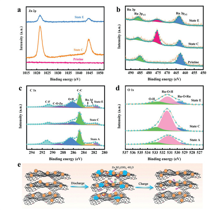
To acquire a deeper comprehension of the ion storage mechanism on the RuO2 NDs/rGO//Zn ZHC, ex-situ XPS characterization was further employed to investigate the changes in surface chemical composition of the electrode at various states. As manifested in Fig. 5a, the high-resolution Zn 2p spectra show that the electrode has a strong Zn characteristic peak at State C, which arises from the generation of Zn4SO4(OH)6·4H2O and the insertion of Zn2+ during the discharge process [47]. After charging to State E, the intensity of characteristic peak of Zn4SO4(OH)6·4H2O is significantly weakened arising from the dissolution of Zn4SO4(OH)6·4H2O and the extraction of most Zn2+. The insertion of Zn2+ is further confirmed in the high-resolution Ru 3p spectra (Fig. 5b), and a new Zn characteristic peak appears upon discharging to State C, which is significantly weakened upon recharging to State E, again confirming the possible pseudocapacitive reaction due to the insertion/extraction of Zn2+ on RuO2. As manifested in the high-resolution C 1s spectra (Fig. 5c), the presence of the characteristic peak of C—O-Zn is detected during the charging and discharging process, confirming the presence of chemical adsorption and desorption reactions between Zn2+ and the oxygen-containing functional groups of rGO, which contributes to a certain amount of pseudocapacitance [48]. As presented in the high-resolution O 1s spectra (Fig. 5d), compared with the initial State A, the characteristic peak of Ru-O-H is significantly enhanced at fully discharged state, and returns to its initial level at fully charged state, which can be attributed to the pseudocapacitance generated by the H+ insertion/extraction during the charging/discharging process, resulting in the improved specific capacitance of the electrode. In summary, the energy storage mechanism of the RuO2 NDs/rGO//Zn ZHC is shown in Fig. 5e.
Figure 5
Figure 5.Ex-situ high-resolution (a) Zn 2p, (b) Ru 3p, (c) C 1s, and (d) O 1s spectra at pristine, State C, and State E of the RuO2 NDs/rGO//Zn ZHC. (e) Schematic representation of the energy storage mechanism of the RuO2 NDs/rGO//Zn ZHC.
In summary, the RuO2 NDs/rGO composite is prepared by sol-gel method combined with low-temperature calcination treatment, and utilized as a cathode for ZHC. Thanks to the synergistic effect of nanoscale design and composite engineering, the RuO2 NDs/rGO//Zn ZHC achieves large specific capacitance (169.5 mAh/g at 0.1 A/g), excellent rate property (74.4 mAh/g at 20 A/g), long cyclic property (90.4% capacity retention after 10,000 cycles at 5 A/g), and maximum energy and power densities (101.7 Wh/kg at 60 W/kg and 41.7 Wh/kg at 12 kW/kg). Moreover, systematic kinetic analyses based on CV and EIS tests elucidate the boosted ion transport kinetics of the RuO2 NDs/rGO//Zn ZHC compared with the RuO2//Zn ZHC. More encouragingly, systematic ex-situ XRD, FESEM, EDS, EIS, and XPS tests are utilized to reveal the energy storage mechanism of the EDL and pseudocapacitive reactions of electrolyte ions in the RuO2 NDs/rGO cathode. This study provides a good strategy for the design and exploitation of high-performance ZHCs pseudocapacitive composite cathode and reveals the energy storage mechanism of RuO2-based pseudocapacitive cathode for the first time.
Declaration of competing interest
The authors declare that they have no known competing financial interests or personal relationships that could have appeared to influence the work reported in this paper.
CRediT authorship contribution statement
Yi Zhang: Writing – original draft, Formal analysis, Data curation. Meiyan Wang: Writing – original draft, Formal analysis. Yirong Zhu: Writing – review & editing, Supervision, Resources, Project administration, Funding acquisition, Conceptualization. Junjun Yao: Methodology, Investigation, Data curation. Rui Zhao: Visualization, Validation, Software. Wenbo Wang: Writing – review & editing.
Acknowledgments
The work is financially supported by Distinguished Young Scientists of Hunan Province (No. 2022JJ10024), National Natural Science Foundation of China (No. 21601057), and Key Projects of Hunan Provincial Education Department (No. 22A0412).
Supplementary materials
Supplementary material associated with this article can be found, in the online version, at doi:10.1016/j.cclet.2025.111037.
Figure 1
(a) Schematic diagram of the synthesis process of the RuO2 NDs/rGO composite. FESEM images of the (b) pure RuO2 and (c) RuO2 NDs/rGO composite. (d) TEM and (e) HRTEM images of the RuO2 NDs/rGO composite. (f) XRD patterns and (g) TG curves of the pure RuO2 and RuO2 NDs/rGO composite. (h) XPS full spectrum and high-resolution (i) C 1s/Ru 3d, (j) Ru 3p, and (k) O 1s XPS spectra of the RuO2 NDs/rGO composite.
Figure 2
(a) Configuration of the RuO2 NDs/rGO//Zn ZHC. (b) CV profiles at 5 mV/s and (c) GCD profiles at 0.3 A/g of the rGO//Zn, RuO2//Zn and RuO2 NDs/rGO//Zn ZHCs. (d, e) GCD profiles at various current densities of the RuO2 NDs/rGO//Zn ZHC. (f) Rate capability of the rGO//Zn, RuO2//Zn and RuO2 NDs/rGO//Zn ZHCs. (g) Ragone plot of the RuO2 NDs/rGO//Zn ZHC in contrast with other ZHCs. (h) Digital images of a small fan driven by two ZHCs. (i) Cycle property and Coulombic efficiency of the RuO2 NDs/rGO//Zn ZHC after 10,000 cycles at 5 A/g.
Figure 3
(a) EIS plot, (b) linear fitting of Z' vs. ω-1/2 plot in the low-frequency region, (c, d) CV curves at various sweep rates, (e) the linear relationship between Ip and v1/2, (f) LogIpvs. logv plots, (g, h) capacitive contribution at 20 mV/s and (i) capacitive contribution ratio at diverse sweep rates of the RuO2//Zn and RuO2 NDs/rGO//Zn ZHCs.
Figure 4Ex-situ XRD patterns of the (a) Zn anode and (b) RuO2 NDs/rGO cathode at various states and corresponding GCD curves at 1 A/g, (c-e) ex-situ FESEM images at different states, (f) ex-situ FESEM image at fully discharged state and (g) corresponding EDS spectrum, and (h) EIS plots at different states of the RuO2 NDs/rGO//Zn ZHC.
Figure 5Ex-situ high-resolution (a) Zn 2p, (b) Ru 3p, (c) C 1s, and (d) O 1s spectra at pristine, State C, and State E of the RuO2 NDs/rGO//Zn ZHC. (e) Schematic representation of the energy storage mechanism of the RuO2 NDs/rGO//Zn ZHC.

 DownLoad:

 下载:
下载:


 下载:
下载:
