Table 1.
Characteristics of various methods for producing H2O2.
Citation:
Junjie Wang, Shulin Gao, Sujuan Hu. Zinc-air battery-H2O2 generation system: Current progress, key challenges, optimization strategies and future developments[J]. Chinese Chemical Letters,
2026, 37(6): 111000.
doi:
10.1016/j.cclet.2025.111000

Zinc-air battery-H2O2 generation system: Current progress, key challenges, optimization strategies and future developments
English
Zinc-air battery-H2O2 generation system: Current progress, key challenges, optimization strategies and future developments
Abstract:
The zinc-air battery (ZAB)-hydrogen peroxide (H2O2) generation system produces H2O2 through a 2-electron oxygen reduction reaction (ORR) at the ZAB air cathode while simultaneously providing external electrical power. This system offers a promising, eco-friendly solution for both energy storage and chemical production. Despite its promise, a comprehensive review of this topic is still scarce. To fill this void, this review discusses the background and mechanisms of the ZAB-H2O2 generation system and covers approaches to achieving efficient and stable operation through 2e− ORR catalyst design and optimization, the regulation of the electrolyte, cathode configuration design, and electrochemical operating conditions. From the perspective of the cathode, anode, electrolyte, and their integration with energy systems, this review systematically analyzes the key challenges and optimization strategies. In addition, this review summarizes the main technical bottlenecks this system faces and proposes potential solutions and development suggestions for future research and practical applications.
-
Key words:
- Zinc-air battery
- / H2O2
- / 2e− ORR
- / Electrochemical catalysts
- / Application
-
1. Introduction
H2O2 is a chemical that plays a significant role in environmental and energy applications. As an environmentally friendly oxidant, H2O2 is widely utilized in various domains, including household, medical, agricultural, and industrial sectors [1-5]. Moreover, H2O2 serves as a sustainable energy carrier. With rapidly growing demand, the total market demand is expected to increase to 5.7 million tons by 2027 [6].
However, the current industrial production of H2O2 is almost entirely dependent on the anthraquinone process, involving continuous hydrogenation and oxidation of anthraquinone molecules [7]. H2O2 is extracted from the organic working solution, leaving the solvent/anthraquinone mixture for recycling. This process can produce an average of 50,000 tons of H2O2 per year per unit and constitutes a major portion of global H2O2 production [8]. Unfortunately, the limitations of the anthraquinone process in modern green chemistry applications are significant, with major problems including high equipment costs, high environmental impact, low reaction efficiency, and time- and energy-intensive separation and purification processes. These shortcomings make it difficult to meet the requirements of sustainable and low-carbon production [9-11].
To avoid these shortcomings of the anthraquinone method, the preparation of H2O2 through the direct reaction of H2 and O2 is more preferable. As long as an efficient catalyst is designed and applied, this partial hydrogenation reaction can be fully achieved under low-temperature conditions [12,13]. However, it should be noted that in this process, expensive palladium-based catalysts are usually selected to limit the occurrence of competitive side reactions. More critically, this method requires extremely precise control of the ratio of H2 and O2 to avoid entering the explosive range, which inevitably results in a low actual yield of direct synthesis [14-16]. Another potential route for H2O2 synthesis is to make use of the enzyme-catalyzed processes in nature. According to current reports, some oxidases, such as glucose oxidase, D-amino acid oxidase, and cholesterol oxidase, can selectively catalyze the corresponding natural substrates to produce H2O2. Nevertheless, due to the relatively weak catalytic activity of these enzymes and their low turnover frequency, the rapid development of this H2O2 biosynthesis technology has been impeded [17,18]. Therefore, there is still a need to develop a more environmentally friendly, efficient, safe, and convenient alternative process for H2O2 production.
In recent years, photocatalysis and electrocatalysis have shown great potential in the in-situ synthesis of H2O2. In the typical photocatalytic process of H2O2 synthesis, three consecutive elementary steps occur on the photocatalyst: First, the semiconductor photocatalyst absorbs excitation light with energy greater than its band gap, generating electrons (e−) in its conduction band (CB) and holes (h+) in its valence band (VB). Second, these photogenerated electrons (e−) and holes (h+) are separated and diffuse to the surface of the photocatalyst. Finally, they react with H2O and O2 to generate H2O2 through different redox pathways [19]. Electrocatalytic method uses an electrochemical reaction to directly reduce oxygen to H2O2. Compared with the traditional anthraquinone method, this method has the advantages of a simple process, low energy consumption, and strong environmental benefits [20-23]. Specifically, H2O2 is produced by 2e− ORR on the cathode, while oxidation reactions such as the oxygen evolution reaction (OER) occur on the anode [24]. This electrochemical method uses O2 and H2O as feedstocks, relies on electricity as an energy input, emits no organic waste, and has a zero-carbon footprint [25,26]. Additionally, the on-site production of dilute H2O2 is feasible with portable and distributed devices, thereby avoiding the hazards associated with the transportation and storage of bulk H2O2 [2,27,28].
With the rapid development of renewable energy technologies, electrochemical energy storage technology has gradually become a key component of the energy system. Zinc-air batteries (ZABs) are widely regarded as one of the most promising solutions for the next generation of energy storage systems due to their high theoretical energy density, low cost, high safety, portability, and rechargeability [29-31]. Traditionally, the design of ZABs has focused on electrical energy storage and release. However, if in-situ electrocatalytic H2O2 production is integrated into these systems, the dual goals of energy conversion and chemical production can be achieved [32-34]. Table 1 shows the characteristics of various methods for producing H2O2 [35-38]. The in-situ preparation of H2O2 during the energy storage process can expand the system’s function from merely storing electrical energy to simultaneously producing high value-added chemicals. This integration not only improves the economic efficiency of the system but also enhances resource utilization, aligning with the principles of modern green chemistry and circular economy. The combination of these two technologies in constructing a ZAB-H2O2 generation system exhibits the following features and advantages (Fig. 1):
Table 1
 DownLoad:
CSV
DownLoad:
CSV
Production method H2O2 selectivity Catalyst type Operating conditions Process characteristics Ref. Anthraquinone process 15%-100% Pd/Ni-based 303–353 K, > 105 Pa Industrial production [35] Direct synthesis > 60% Pd-based 273–313 K Distributed production [36] Active enzyme-catalyzed ~310 K Biomedicine [37] Electrocatalysis 30%-100% Noble Metal–based
Carbon–based
Non–Precious Transition MetalRoom temperature and atmospheric pressure Distributed productionIn-situ production [38] Photocatalysis > 90% g-C3N4, TiO2,
BiVO4, CdS, MOFVisible light or
simulated light sourceDistributed productionIn-situ production [38] ZAB-H2O2 generation system 80%-100% Carbon–based
Non–precious Transition MetalRoom temperature
and atmospheric pressureDistributed productionIn-situ production
Self-generated electricity[89,94,96,101,104,110,114,122] Figure 1
 Figure 1. Advantages and applications of the zinc-air battery-hydrogen peroxide generation system.
(1) High energy utilization efficiency: This combination not only provides a solution for power storage but also enables the production of an important chemical, H2O2, in the same system, achieving the versatility of energy storage and chemical production [39].
(2) High safety, low cost, and complexity: The electrochemical method can be operated at room temperature and pressure, avoiding the explosion risk associated with H2 and O2 gas mixtures. Preparation of dilute H2O2 on-site reduces safety hazards during transportation and storage. Compared with the traditional anthraquinone process, the electrochemical preparation of H2O2 simplifies production steps and reduces the need for large-scale equipment and infrastructure, thereby lowering production costs [7,40].
(3) Promote distributed production: The portability and adjustability of electrochemical methods enable distributed in-situ production of H2O2, especially in areas far from centralized chemical plants and in locations where urgent disinfection and environmental purification are required [41-44].
(4) In line with the principle of green chemistry: Electrochemical in-situ synthesis of H2O2 uses water and air as raw materials and renewable energy as a power source, reduces dependence on harmful chemicals and environmental pollution, and achieves zero carbon emissions [10,45].
To sum up, the combination of H2O2 production and energy storage technology is not just a simple superposition of functions, but creates an advanced technology platform through overall system optimization. The platform is characterized by efficient energy conversion, energy-efficient production, and multifunctional applications. As a representative of efficient energy storage technology, the combination of ZABs and H2O2 generation technology marks a new technological path in the energy and chemical industries. This innovation is expected to drive technological progress in this field, open up new application scenarios, and provide important support for the future development of green energy and chemical industries. Fig. 2 shows timeline of the ZAB-H2O2 generation system development. However, there is currently a lack of comprehensive review literature in this field. In order to fill this gap, this review first introduces the reaction mechanism of the ZAB-H2O2 generation system and focuses on how to achieve efficient and stable ZAB-H2O2 generation through catalyst design and optimization, electrolyte regulation, cathode configuration design, and adjustment of electrochemical operating conditions. At the same time, the current challenges and optimization strategies are discussed from the perspectives of the cathode, the anode, the electrolyte, and their integration with energy systems. Finally, we summarize the main problems faced by the ZAB-H2O2 generation system and outline the future development prospects.
Figure 2
 Figure 2. The timeline of the ZAB-H2O2 generation system development.
2. Mechanism and principles of the zinc-air battery-hydrogen peroxide generation system
2.1 Electrocatalytic mechanism of 2e− ORR to H2O2
2.1.1 Background of the 2e− ORR to H2O2
In the ZAB-H2O2 generation system, the ORR at the cathode can proceed through two main pathways: the 2e− pathway for H2O2 production and the 4e− pathway for H2O production [24,46-48]. Generating H2O2 via the 2e− pathway has important applications, especially in environmental and industrial applications [6,10,49]. However, the challenge lies in achieving high selectivity for H2O2 over H2O, as H2O is the more thermodynamically favorable product [50-52]. In order to effectively manage and enhance selectivity for the 2e− pathway, a deep understanding of the underlying electrochemical mechanisms is essential.
2.1.2 Reaction pathway
The ZAB-H2O2 generation system involves the ORR at the cathode. The main electrocatalytic oxygen reduction pathway for H2O2 production is the 2e− pathway, while the pathway for H2O production is the 4e− pathway. The specific reaction steps of these two pathways are as follows [16,46-48,53,54]:
2e− ORR pathway:
(1) Firstly, O2 are adsorbed on the catalyst surface and react with protons and electrons to form an intermediate * OOH ((1), (2)).
$\mathrm{O}_2+\left(\mathrm{H}^{+}+\mathrm{e}^{-}\right) \rightarrow {^*\mathrm{OOH}}$ (1) (2) Then, the *OOH further reacts with protons and electrons to form H2O2.
${ }{^*\mathrm{OOH}}+\left(\mathrm{H}^{+}+\mathrm{e}^{-}\right) \rightarrow \mathrm{H}_2 \mathrm{O}_2$ (2) 4e− ORR pathway:
(3) O2 are adsorbed on the catalyst surface and react with protons and electrons to form a *OOH ((3), (4), (5), (6)):
$\mathrm{O}_2+\left(\mathrm{H}^{+}+\mathrm{e}^{-}\right) \rightarrow {^*\mathrm{OOH}}$ (3) (4) The OOH* further reacts with protons and electrons to form adsorbed *O:
${ }{^*\mathrm{OOH}}+\left(\mathrm{H}^{+}+\mathrm{e}^{-}\right) \rightarrow{ }^* \mathrm{O}+\mathrm{H}_2 \mathrm{O}$ (4) (5) The adsorbed *O continues to react with protons and electrons to form adsorbed OH*:
${ }^* \mathrm{O}+\left(\mathrm{H}^{+}+\mathrm{e}^{-}\right) \rightarrow{ }^* \mathrm{OH}$ (5) (6) *OH ultimately reacts with protons and electrons to form H2O:
${ }^* \mathrm{OH}+\left(\mathrm{H}^{+}+\mathrm{e}^{-}\right) \rightarrow \mathrm{H}_2 \mathrm{O}$ (6) 2.1.3 Free energy diagram, kinetics and volcano plots for 2e− ORR to H2O2
In ORR, there is significant competition between the 4e− pathway and the 2e− pathway, as shown in Fig. 3a [55]. Since H2O is a more thermodynamically favorable product, this presents a challenge for the synthesis of H2O2 via the 2e− ORR pathway. The *OOH intermediate is a significant intermediate in the 2e−- and 4e−-ORR pathways, and the binding free energy (ΔG(*OOH)) of the *OOH intermediate plays a primary role in determining the catalytic activity and selectivity in H2O2 generation [55]. Thus, the final product of ORR is largely determined by the electrochemical catalyst used.
Figure 3
 Figure 3. (a) Schematic illustration of the reactions and the equilibrium potentials during the O2 electroreduction. Reproduced with permission [55]. Copyright 2019, ACS Publications. (b) Free energy diagram for the four-electron (blue line) and two-electron (red line) oxygen reduction. The electrochemical barrier for the *OOH to H2O2 or *O are illustrative and indicate the importance of kinetics in determining catalyst selectivity. Reproduced with permission [56]. Copyright 2018, ACS Publications. (c) Limiting potentials for individual steps in (7), (8), showing the strongly bound *OH region (solid red line) and weakly bound *OOH region (solid bule line) for the two-electron process. The color gradient indicates the strong *OH and weak *OOH binding regions. Reproduced with permission [56]. Copyright 2018, ACS Publications. (d) Operating mechanism of ZAB-H2O2 generation system.
The ideal catalyst should possess a binding energy for the *OOH intermediate that is neither excessively strong nor too weak [56-60]. According to the free energy diagram (Fig. 3b) and related scaling relations, it is crucial to prevent the dissociation of the O-O bond in the *OOH intermediate to avoid the 4e− pathway. This means that catalysts with strong oxygen binding energy, which encourage the formation of *O, are unsuitable for the 2e− ORR, favoring instead catalysts with weaker oxygen binding energy. The two-electron volcano plot in Fig. 3c illustrates the dynamics of each reaction step by plotting the limiting potential against ΔG(*OH). In particular, the red and blue lines represent the limiting potentials for the steps in Eqs. 7 and 8, respectively. Because there is only one *OOH intermediate in the catalytic process, these two lines meet at the peak of the volcano plot, corresponding to an equilibrium potential of 0.70 V. This intersection indicates the theoretical possibility of designing an ideal electrochemical catalyst with activity at the peak of the volcano plot. On the left side of the plot, a catalyst with strong *OOH (or *OH) binding energy (solid red line) may have the *OOH → H2O2 step as the limiting step, leading to a preference for the 4e− ORR over the 2e− pathway. On the other hand, a catalyst on the right side of the volcano plot with weaker *OOH binding energy (solid blue line) will have the O2 → *OOH step as the limiting step, potentially increasing H2O2 selectivity but lowering overall activity [56].
$U_{\mathrm{L} 1}=-\Delta G(^* \mathrm{OH})+1.72$ (7) $U_{\mathrm{L} 2}=\Delta G\left({ }^* \mathrm{OH}\right)-0.32$ (8) 2.2 Operational mechanism of zinc-air battery-hydrogen peroxide generation system
ZAB is electrochemical system composed of an air electrode, an electrolyte, and a zinc anode [61-63]. In this system, electrical energy is released through the dissolution process of zinc at the anode and the ORR at the cathode [64-68].
Metallic Zn at the anode reacts with OH− from the electrolyte to form ZnO, releasing electrons to the external circuit [69-71]. This reaction can be represented as Eq. 9:
(9) Concurrently, O2 from the air is reduced at the cathode (air electrode) through the 4e− ORR (Eq. 10). This process consumes electrons and generates OH− that migrate towards the anode to participate in the oxidation of Zn.
(10) While 2e− ORR to form H2O2 at the cathode can be described as Eq. 11:
(11) After analyzing the operating mechanism of the ZABs and the electrocatalytic ORR mechanism for H2O2 production, it is easy to understand the operational mechanism of the ZAB-H2O2 generation system (Fig. 3d). The overall reactions are as follows (Eqs. 12-14):
(12) (13) (14) In ZAB, 2e−-ORR is a key electrochemical process for H2O2 generation [72]. The activity and selectivity of an ideal 2e− ORR catalyst is crucial, where the activity depends on the kinetic barrier of O2 activation and the strength of *OOH binding on the catalyst surface, while the selectivity is determined by the kinetic barrier of *OOH proton-dissociation [49]. Thus, the main challenge of this system is to design and optimize the catalyst to not only enhance activity by decreasing the kinetic barriers to O2 activation and *OOH formation, but also to realize high selectivity by precisely regulating the binding strength of the intermediates. Maintaining this balance is critical to impede the over-reduction of *OOH to H2O, while ensuring efficient H2O2 generation. In addition, the stability of the catalyst under operating conditions is significant to keep long-term performance. Therefore, developing catalysts that can simultaneously solve these challenges is vital for advancing the practical application of H2O2 generation in ZABs.
3. Achieving efficient, highly selective, and stable in-situ hydrogen peroxide generation in zinc-air battery
This section focuses on strategies to improve in-situ H2O2 generation efficiency while maintaining stable battery discharge performance. Achieving this balance is crucial to the application prospects and technical optimization of ZABs. The following sections give guide strategies for the design and optimization of catalysts, electrolytes, and cathodes, as well as for electrochemical operating conditions. Table 2 shows the literature on ZAB-H2O2 generation system in the past five years.
Table 2
Table 2. The reported literatures on the ZAB-H2O2 production systems in the past five years.DownLoad:
CSV
Cathode Anode Electrolyte OCV (V) Current density (mA/cm2) Power density Duration of operation (h) Faradaic efficiency H2O2 production rate H2O2 selectivity Ref. S-NiP4Mo6 Zn plate KOH (4.0 mol/L) and Zn(OAc)2·2H2O (0.2 mol/L) - 10 - 25 83.9% 4.48 mol gcat−1 h−1 96.5%-98.3% [94] Thiophene-S doped carbon Zn foil KOH (6 mol/L) ~1.3 20 82.7 ± 0.8 mW/cm2 8 92.8% ± 0.2% 117.7 ± 0.2 mg·mgCat−1·h−1 > 90% [96] OCNTs@NF Zn rod Na2SO4 (0.5 mol/L) ~0.9667 10 ~36 - 162.5 mg L−1 h−1 92% [114] aCB Zn plate KOH (6 mol/L) and Zn(AC)2 (0.2 mol/L) ~1.3 45 41 mW/cm2 4 85% 20.3 mg cm−2 h−1 > 94% [89] Ni-LDH Zn foil KOH (1 mol/L) ~1.18 10 10 mW/cm2 > 16 95% 14.25 mg cm−2 h−1 87% [101] pTTh Zn foil KOH (6 mol/L) ~1.1 253.5 µW/cm2 > 3 - 34.8 mg L−1 h−1 80%-100% [122] HMCS-8 Zn foil KOH (6 mol/L) and Zn(AC)2 (0.2 mol/L) ~1.3 10 166 mW/cm2 - - - > 90% [104] INAD MP-Ti-ENTA/SnO2-Sb2O3 Na2SO4 (0.1 mol/L) - 100 - ~6 > 90% 7.63 mg cm−2 h−1 - [110] 3.1 Catalyst design and optimization
The ideal 2e− ORR catalyst should have high activity, high selectivity and high stability, and be able to show excellent catalytic performance under various operating conditions [21,73]. Future research should focus on developing low-cost, efficient and stable catalysts to meet the needs of large-scale applications. 2e− ORR catalyst should meet the following criteria: (1) High activity; (2) low catalyst loading; (3) appropriate electrical conductivity; (4) ideal mass transfer rate and high initial potential/limited diffusion current density; (5) high selectivity to ensure a high yield of H2O2 rather than H2O; (6) high stability to ensure long-term durability in various electrolytes (Fig. 4) [1,74-76]. For 2e- ORR catalysts, the bonding strength of O2 on the catalyst surface should be sturdy enough to facilitate the formation of *OOH, but the adsorption of *OOH should not be too strong or too weak for favor the rapid desorption of H2O2 [77]. Thus, the selectivity of ORR can be controlled by adjusting the electrocatalyst’s ability to bind to O₂ and its interaction with *OOH intermediates [78]. To effectively regulate these interactions, consider the guidelines below and incorporate relevant case studies to illustrate these principles (Fig. 5).
Figure 4
 Figure 4. Criteria for an ideal 2e− ORR catalyst.
Figure 5
 Figure 5. Design and optimization strategies for 2e− ORR catalyst. Sequentially from top to bottom. Reproduced with permission [83]. Copyright 2019, ACS Publications. Reproduced with permission [89]. Copyright 2018, ACS Publications. Reproduced with permission [96]. Copyright 2024, ACS Publications. Reproduced with permission [101]. Copyright 2020, Wiley. Reproduced with permission [104]. Copyright 2022, ACS Publications.
3.1.1 Selection of catalyst materials
Selecting the appropriate catalyst material is crucial. Different materials, such as metals, alloys, carbon-based materials, or metal oxides, have distinct electronic properties and surface activities. These characteristics directly affect their ability to bind with O2 and interact with *OOH. Precious metals like Pt and Pd usually have a strong *OOH adsorption ability, which easily promotes O-O bond cleavage, thus favoring the 4e− ORR [79]. Alloying or adjusting the particle size can mitigate this strong interaction. Alloying can introduce a second metal element, which adjusts the d-band center position of the catalyst, thereby weakening the interaction with the OOH intermediate and making the catalyst more inclined towards the 2e− ORR pathway [80,81]. For instance, alloyed Pt-Hg nanoparticles exhibit high selectivity and catalytic activity due to their unique electronic structure and lower *O adsorption energy [82]. However, the scarcity and high cost of precious metals limit their large-scale application.
Non-precious metal catalysts, such as single-atom catalysts (SACs), are prone to 2e− ORR due to their high mass activity and moderate *OOH intermediate adsorption energy. For example, Sun et al. designed a series of M-N-C catalysts with M-Nx structures (M = Mn, Fe, Co, Ni, Cu) and used density functional theory (DFT) calculations to research the relationship between the binding free energy of HO* intermediates (ΔG(HO*)) and H2O2 selectivity for different M-N-C catalysts. The results showed that the HO* binding free energy of Co-N-C catalysts is near the peak of the volcano plot for H2O2 generation. By analyzing ΔG(HO*), the research explained the high selectivity mechanism of Co-N-C catalysts in H2O2 generation, which lies in their moderate HO* binding energy. This allows for effective O2 adsorption while preventing O-O bond cleavage. In industrial applications, Co-N-C catalysts have proven efficient H2O2 production ability under strong alkaline conditions, confirming their potential for industrial use. At a current density of 50 mA/cm2, the H2O2 production rate of Co-N-C catalysts reached 4.33 mol gcatalyst−1 h−1. The pH of the electrolyte greatly influences the catalyst performance, with the highest H2O2 selectivity and production rate gained under strongly alkaline conditions. These results show their efficient production ability at high current densities [83]. However, using HO* binding energy as a descriptor in the study to replace directly calculating HOO* binding energy, while simplifying the computational process, has potential limitations. HO* binding energy is mainly related to 4e− ORR and does not directly reflect the specific reaction energy changes of the key intermediate HOO* in 2e− ORR. To overcome this issue, a multi-descriptor approach should be adopted, combining the binding energies of intermediates such as HO*, HOO*, and O*, to construct a more comprehensive reaction energy diagram. Simultaneously, experimental validation of the computational results should be conducted to guarantee their accuracy and applicability, and theoretical models and descriptors should be dynamically adjusted. Using high-throughput screening and machine learning techniques can quickly screen and optimize catalysts, guaranteeing they possess high activity, high selectivity, and high stability in actual environments [84,85].
3.1.2 Surface functionalization
Surface functionalization involves the introduction of different chemical groups on the catalyst surface [86]. These chemical groups can modulate the surface electron density and change the interactions between the catalyst and intermediates, thereby affecting the reaction pathway. On carbon-based catalysts (such as graphene and carbon nanotubes), introducing hydroxyl (OH), carbonyl (C=O), and carboxyl (COOH) groups can adjust the electronic structure by electron-donating or electron-withdrawing effects, which affects the interaction with the *OOH intermediate [87,88].
For example, Wang et al. successfully prepared a highly active oxidized carbon electrocatalyst (aCB) by annealing at 500℃ in air for 45 min. Through this simple activation process, various oxygen-containing groups were introduced onto the carbon black surface, including hydroxyl (-OH), aldehyde (-CHO), and epoxy (C-O-C) groups, which significantly impact H2O2 production. RRDE test results indicated that aCB exhibits high catalytic activity in 0.1 mol/L O2-saturated KOH, with a half-wave potential of 0.736 V and an onset potential of 0.821 V, indicating a low overpotential (< 5 mV). DFT calculations revealed the effects of different oxygen groups on H2O2 production. The results showed that C-O-C and -CHO groups show the best adsorption energies for the HOO* intermediate, with adsorption energies near the peak of the volcano plot, indicating these groups effectively promote H2O2 generation. Experimental results suggested that aCB catalysts with C-O-C and -CHO groups exhibited higher selectivity and activity for H2O2 production. Based on this design, this system achieved a power density of 360 W/m2 at a discharge potential of 0.8 V, with an H2O2 production rate of 5.93 mol m−2 h−1 [89].
3.1.3 Doping engineering
Doping is an important method to modify catalytic performance by introducing heteroatoms into materials, thereby changing their electronic structure and surface chemical properties. Doping elements such as nitrogen (N), sulfur (S), and phosphorus (P) can significantly change the electronic structure [90]. These changes include electron density, electronegativity, and the electron-donating ability, directly affecting the adsorption of *OOH intermediates.
(1) N doping: N atoms have high electronegativity, and lone pair electrons are introduced when they incorporated into carbon-based materials, forming new active sites (such as pyridinic-N and pyrrolic-N) [91]. These sites can effectively stabilize *OOH intermediates, optimizing their adsorption energy, making the reaction more inclined towards the 2e− ORR pathway and thus facilitating H2O2 production.
(2) S doping: S atom doping introduces a larger atomic radius and lower electronegativity, which increases the electron density and π-π conjugation structure of carbon materials, optimizing the adsorption energy of *OOH intermediates [92]. Sulfur doping often results in higher H2O2 selectivity because its adsorption on *OOH intermediates is relatively weak, reducing the likelihood of O-O bond cleavage.
(3) P doping: P atoms have a larger atomic radius and higher electronegativity. Doping forms C-P bonds, altering the local electron density of carbon-based materials [93]. This change can enhance the stability of *OOH intermediates, promoting the 2e− ORR pathway and enhancing the H2O2 generation.
Wang et al. S-NiP4Mo6 was synthesized by S-doped polymetallic oxides (POMs) under hydrothermal conditions, and the ORR pathway was adjusted [94]. By introducing S atoms, the electronic structure of the catalyst is altered, resulting in a precise transition from the 4e-reduction pathway to the 2e− reduction pathway. The key mechanism of this transition lies in the difference in electronegativity between oxygen and sulfur. For NiP4Mo6, tends to 4e− ORR due to the excessive adsorption of OOH*, which promotes O-O cleavage. When an O2− is replaced by S2−, sulfidation can weaken the adsorption of OOH* and hinder the cleavage of O-O, and S-NiP4Mo6 exhibits 2e− characteristics in the oxygen reduction reaction. At 0.3 V vs. RHE, the H2O2 yield was as high as 4.48 mol g cat−1 h−1, and the Faraday efficiency was as high as 83.9%. In addition, S-NiP4Mo6 also has demonstrates good photothermal effect. Under photothermal heating, H2O2 produced by 2e− ORR decomposes and regenerates ·OH free radicals, which can degrade phenol, antibiotics, pesticides and other organic pollutants. The undoped NiP₄Mo₆ catalyst remains highly effective in ZAB applications, demonstrating the versatility of POM-based materials in different applications. This comparison highlights the importance of targeted doping strategies in optimizing catalyst performance for specific reactions and applications [95].
Xie et al. utilized thiophene-S as a doping source to introduce S into carbon-based materials through a molecular weaving strategy (Figs. 6a-d), resulting in S-doped carbon materials with up to 14 wt% S content. The S atoms are mainly located at the edges or defect sites of the carbon framework, forming C-S-C bonds (Fig. 6e). This edge-doping configuration aids in creating more active sites on the surface of carbon material. Due to the higher electronegativity of S, it induces a redistribution of electron density in the carbon framework, forming regions rich in charge. The carbon atoms near the edge-doped sulfur atoms exhibit higher catalytic activity, favoring the stable adsorption of *OOH intermediates and promoting the 2e− ORR [96]. This study constructed a volcano plot based on ΔGOOH* to describe the catalytic activity of different S-doped carbon materials in the 2e− ORR (Fig. 6f). The results show that S-doped carbon materials with a thiophene-S configuration have their ΔGOOH* located near the right side of the volcano plot, close to the peak, suggesting optimal 2e− ORR activity. When ΔGOOH* is within a moderate range, the *OOH intermediates can effectively adsorb onto the catalyst surface without becoming too stable, making it easier for them to dissociate and produce H2O2. Sulfur doping optimizes the adsorption energy of *OOH intermediates, reducing the likelihood of O-O bond cleavage, thereby significantly enhancing the selectivity for H2O2. Within the potential range of 0.48–0.78 V (vs. RHE), the H2O2 selectivity of thiophene-S doped carbon material is significantly higher than that of undoped carbon materials, increasing with the S doping amount. The thiophen-S-doped carbon-based battery achieves a peak power density of 82.7 ± 0.8 mW/cm2 at a current density of 130.9 mA/cm2 (Figs. 6g and h). At a potential of 0.66 V (vs. RHE), the H2O2 selectivity of 14 wt% thiophene-S doped carbon material reaches as high as 93% (Fig. 6i).
Figure 6
 Figure 6. Synthesis and characterization of the thiophene-S-doped carbon catalysts. (a) Schematic illustration of the preparation of thiophene-S doped carbon material. (b, c) SEM and TEM images of the thiophene-S-doped carbon. (d) TEM-EDS mapping of the thiophene-S-doped carbon. (e) Simulated different S doping configurations. The carbon atom marked by a red dashed circle represents the calculated active site. (f) Calculated 2e− ORR volcano plot. The black squares display the activities of the best-performing Au, Pd, Pt, and PtHg4 alloys. (g) Schematic illustration of the Zn-air battery producing H2O2. (h) Polarization curve and power density plot. (i) Galvanostatic polarization curve at 20 mA/cm2 with a continuous supply of O2 to the cathode (O2 feed rate = 20 sccm). Reproduced with permission [96]. Copyright 2024, ACS Publications.
Doping techniques show strong potential in regulating ORR process. The electronic structure and interface properties of the catalyst were greatly modified by the introduction of heteroatoms, and the catalytic activity was enhanced [97]. Future researches could further study the effects of other doping elements and their combinations on ORR. For example, N, P, and B elements may result in different electronic structural changes. In addition, by combining two or more doping elements (such as N-S, N-O), the synergistic effect between elements may be achieved, which further optimizes the electronic structure and increases the number of active sites. Meanwhile, computational methods like DFT are suggested to be used for understanding the impacts of doping elements on the electronic structure and ORR reaction pathways, offering theoretical guidance for the design of new catalysts. In addition, machine learning (ML) methods can greatly help to understand the optimization of doping strategies and the development of new catalysts. By integrating experimental data with computational simulation data, ML models can quickly predict the effects of different doping elements and their combinations on catalytic performance. For instance, ML algorithms can use data-driven approaches to identify doping elements and combinations with optimal electronic structures and reaction activities. In summary, the integration of machine learning methods into doping research will further improve the development of efficient and cost-effective electrocatalysts.
3.1.4 Defect engineering
Defects can significantly impact the electronic structure and reaction activity of catalysts. In the 2e− ORR process, defects alter the surface electron density and the distribution of active sites, effectively regulating the adsorption and reaction pathways of intermediates [98,99]. These defects, due to incomplete atomic coordination, possess high chemical reactivity [100]. The high activity sites at edge defects can effectively stabilize *OOH intermediates, reducing the likelihood of O-O bond cleavage, thus promoting the 2e− ORR.
Huang et al. employed a "one-pot" strategy to embed high-density, ultrathin Ni-LDH (layered double hydroxide) nanosheets into in-situ grown carbon nanosheets, forming Ni-LDH/carbon nanosheets (Ni-LDH/CNSs). DFT calculations were used to explore the 2e− ORR activity mechanism. Edge defects in the Ni-LDH nanosheets alter the local electron density, creating high activity sites that significantly enhance the adsorption and stability of *OOH intermediates, thereby promoting the 2e− ORR pathway and aiding in the production of H2O2. The abundant oxygen defects in the Ni-LDH/CNSs serve as active sites, contributing to increased catalytic activity. A volcano plot based on ΔGOOH* was constructed to showcase the performance of catalysts with different defect configurations in the 2e− ORR. The results indicate that the ΔGOOH* of Ni-LDH edge defects is located near the peak of the volcano plot, demonstrating high catalytic activity [101].
The strategic incorporation of defects into catalytic materials offers a promising avenue for fine-tuning their properties to meet specific reaction requirements. By carefully designing and controlling defect types and distributions, researchers can create catalysts that are not only more active but also more selective for desired reactions. Moreover, the integration of advanced characterization techniques, such as in-situ spectroscopy, will provide deeper insights into the dynamic behavior of defects under operational conditions. This understanding will be instrumental in developing robust catalysts that maintain high performance over extended periods.
3.1.5 Microstructure regulation
Microstructure affects the ORR pathways through various mechanisms, including the mass transfer efficiency of reactants and products, the accessibility of surface active sites, the transfer of electrons and protons, adsorption behaviors, the stability of intermediates, and the chemical environment of the catalyst surface [102,103]. By rationally designing and optimizing the microstructure, it is possible to effectively regulate ORR pathways, favoring the 2e− pathway to generate in-situ H2O2 instead of the 4e− pathway that produces water. This regulation is crucial for developing efficient electrocatalysts.
Wang et al. found that in the 2e− ORR, oxygen as a reactant must be rapidly delivered to the catalyst surface for reduction. The microstructure, including pore size and morphology, directly influences the diffusion path and rate of oxygen (Figs. 7a and b). Larger pore sizes provide smoother oxygen channels, reducing diffusion resistance and thereby enhancing reaction efficiency. Additionally, H2O2, as a product of the 2e− ORR, needs to be promptly removed from the catalyst surface to prevent its further reduction to water via the 4e− reaction. Large-pore structures facilitate the rapid discharge of H2O2, reducing its residence time on the catalyst surface, thus maintaining high selectivity and yield. In practical applications, such as ZAB or wastewater treatment systems, medium-to-large pore structures (e.g., 8 nm) can provide higher power densities and faster reaction rates under high current densities (Fig. 7d), rather than solely relying on initial electrochemical test results under laboratory conditions. Additionally, the pore size and morphology within the microstructure determine the specific surface area of the catalyst. Smaller pore sizes typically provide a higher specific surface area, increasing the exposure of active sites and thereby enhancing catalytic activity. However, if the pores are too small, severe mass transfer limitations may occur at high current densities, reducing overall reaction efficiency (Fig. 7c). The microstructure can influence the ORR pathways. Appropriate pore structures help control the adsorption and reaction patterns of oxygen molecules on the catalyst surface, favoring the 2e− reduction to generate H2O2 rather than the 4e− reduction to produce water. For instance, medium pore sizes (such as 8 nm) can balance reactant mass transfer and active site exposure, thereby increasing H2O2 selectivity [104].
Figure 7
 Figure 7. (a) Diagram illustrating the role of mesoscale engineering in regulating H2O2 production in zinc-air batteries; Scheme, STEM images (scale bar: 100 nm), enlarged STEM images (scale bar: 20 nm), and pore size distribution of (b) HMCS-3 nm, HMCS-5 nm, HMCS-8 nm, HMCS-10 nm and HMCS-12 nm. (c) Simulated velocity field and flow rate at the cross-section of HMCS-3 nm, HMCS-5 nm, HMCS-8 nm, HMCS-10 nm, and HMCS-12 nm. Flow rate comparison of HMCS samples. (d) Schematic of Zn-air battery with on-site production of H2O2 for wastewater treatment. UV-vis absorption spectra of RhB solution treated by Zn-air battery with HMCS-8 nm as the cathode. Concentration evolution of RhB over treatment time. (inset) Digital photographs of the RhB solution before and after purification. Reproduced with permission [104]. Copyright 2022, ACS Publications.
Pore structures affect the local environment on the catalyst surface, including pH and local electric field strength, which significantly impact ORR pathway selection. For example, larger pore structures may help maintain lower H2O2 concentrations on the surface, reducing the chances of its further reduction to water. Catalysts with well-designed pore structures can maintain structural stability during reactions, minimizing deformation or failure caused by product accumulation or hindered reactant mass transfer. Larger pores not only provide better mass transfer channels but also alleviate catalyst surface blockage caused by product accumulation, enhancing catalyst durability [105].
The key to optimizing catalyst ORR performance is to adjust the porosity and morphology. Smaller pores increase the surface area and the number of active sites, but reduce the mass transfer rate at high current conditions. Larger pores are conducive to improving the oxygen mass transfer rate, but reduce the number of active sites. Therefore, an integrated macro pore is designed. The layered pore structure of mesoporous and microporous is a viable way to be compatible with efficient mass transfer and maintain a high density of active sites. In addition, advanced manufacturing techniques, such as 3D printing and self-assembly, provide viable solutions for complex pore structures that are related to the local reaction environment (pH and local electric field strength). Maintaining a controlled pH and local electric field strength can further affect the adsorption and stability of the intermediates, enabling the reaction to develop in the desired path [106]. Computational simulations can help better understand how different pore structures affect catalytic performance. This approach can help determine the most effective pore design for a particular reaction, thereby developing efficient and durable catalysts.
In conclusion, the regulation of microstructure is an effective strategy to optimize catalysts. By adjusting pore morphology, researchers can develop catalysts with high activity, selectivity and stability.
3.2 Regulation of electrolyte
Electrolytes can regulate the 2e− and 4e− ORR pathways by adjusting the solvation structure, mass transfer pathways of reactants, and the selectivity of electrochemical reactions (Fig. 8a). Due to the lack of specific cases of electrolyte regulation in ZAB-H2O2 generation, we will use a similar system—the sodium-air battery-hydrogen peroxide generation system—as an example to analyze practical cases of electrolyte regulation. Yang et al. proposed a strategy to control 2e−/4e− transfer by designing the solvation structure of electrolytes. The main reason electrolytes can regulate 2e− and 4e− reaction pathways lies in changes to their solvation structure and solvation energy. In low-concentration electrolytes, Na+ ions are primarily solvated by water molecules, forming a "salt-in-water" structure. In this scenario, Na+ ions form strong solvation shells with water molecules, making it difficult for Na+ to desolvate, i.e., to be released from the surrounding water molecules. This high solvation energy hinders Na+ ions from approaching the cathode surface for reactions, thus promoting the 4e− reaction. Here, free water molecules can more easily reach the cathode surface, participate in ORR, generate OH−, and eventually form NaOH. In high-concentration electrolytes, Na+ ions primarily coordinate with FSI− anions, forming a "water-in-salt" structure. In this structure, the number of water molecules is significantly reduced, and Na+ ions are mostly surrounded by FSI− anions. The solvation energy is significantly lowered, making it easier for Na+ ions to be released from their solvation shells and approach the cathode surface for reactions, thus promoting the 2e− reaction. In this case, due to the reduction in free water molecules, it is more difficult for water molecules to reach the cathode surface, thereby inhibiting the 4e− reaction (Fig. 8b) [107].
Figure 8
 Figure 8. (a) The regulation strategies of electrolytes for 2e− ORR. (b) Free energy diagram of the 4e− to 2e− reaction in SAB. The star "*" denotes the free site or the adsorption species. (c) Variation in the number of oxygen atoms from water (nO(H2O)) and FSI− anions (nO(FSI)) at the first solvation sheath of Na+ and the fraction of free water not bound to any species. (d) The structures of Na(H2O)5−x(FSI)x with x ranging from 0 to 5. The value represents the solvation energies of Na and the color indicates the electrostatic potentials. (e) The interaction energies between Na+ and ligands in various situations. (f) Reaction mechanism diagram of SABs with different concentration electrolytes. Reproduced with permission [107]. Copyright 2022, Wiley. (g) Future research strategies on electrolytes for ZAB-H2O2 generation system.
Additionally, through DFT calculations and molecular dynamics (MD) simulations, researchers have revealed how changes in solvation structure at different electrolyte concentrations affect the ORR pathways in sodium-air batteries. In low-concentration electrolytes, Na+ ions are primarily solvated by water molecules, forming strong solvation shells with a solvation energy of -5.65 eV (Figs. 8c and d). This highly solvated structure makes it difficult for Na+ ions to desolvate, hindering their contact with the cathode surface and favoring the 4e− reaction, producing NaOH. As the electrolyte concentration increases, the solvation environment around Na+ changes significantly. At moderate concentrations, the solvation structure of Na+ becomes uneven, with a solvation energy of -6.32 eV. In this scenario, Na+ ions are still mainly solvated by water molecules and a few FSI− anions, but the reduction in free water molecules starts to make the 2e− reaction possible. In high-concentration electrolytes (e.g., 27 m and 35 m), Na+ ions primarily coordinate with FSI− anions, forming a "water-in-salt" structure, with a significantly lowered solvation energy, reaching as low as +3.25 eV. This lower solvation energy makes it easier for Na+ ions to desolvate, allowing them to rapidly reach the cathode surface and react with oxygen, promoting the 2e− reaction and producing Na2O2. By adjusting the electrolyte concentration to control the solvation environment and mass transfer behavior of Na+ ions, the ORR pathways can be dynamically regulated (Figs. 8e and f).
Future research should further explore the relationship between electrolyte concentration and solvation environment to optimize the efficiency of 2e− ORR. Additionally, the potential of different types of electrolytes (such as organic electrolytes and ionic liquids) in regulating 2e− ORR should be studies, examining their effects on ion solvation structures and reaction pathways. By introducing advanced characterization techniques, such as in-situ Raman spectroscopy, electrochemical in-situ microscopy, and synchrotron X-ray analysis, real-time monitoring of solvation structure changes and reaction pathways in electrolytes can be used. Research on functionalized electrolytes should be conducted to further enhance the regulatory capability and stability of electrolytes. Ultimately, all the strategies will contribute to the development of a highly efficient and stable electrolyte for the ZAB-H2O2 generation system (Fig. 8g).
3.3 Cathode configuration design
The importance of cathode design and battery configuration in 2e− ORR performance is multifaceted, involving improvment in oxygen transport efficiency, optimization of charge transfer resistance, and appropriate control of electrode thickness and current density (Fig. 9) [108]. These optimizations can boost in-situ H2O2 production efficiency and current efficiency, reduce energy consumption, and provide theoretical foundations and design guidance for practical applications.
Figure 9
 Figure 9. The influence of oxygen transport efficiency, charge transfer resistance, and electrode thickness and current density on the 2e− ORR of H2O2. Reproduced with permission [110]. Copyright 2022, ACS Publications. Reproduced with permission [112]. Copyright 2024, Elsevier. Reproduced with permission [113]. Copyright 2009, ACS Publications.
Oxygen transport rate is one of the critical factors in 2e− ORR performance. Traditional electrolytes exhibit low oxygen transport rates, limiting reaction rates and H2O2 production efficiency [109]. Designing porous cathodes, such as Integrated Natural Air Cathodes (INAC), can significantly enhance oxygen transport rates, thereby improving reaction rates and H2O2 production efficiency [110]. The design of a three-phase interface (liquid-gas-solid) enables efficient diffusion of oxygen to the catalyst surface, increasing oxygen utilization. Compared to traditional designs immersed in liquid, facing the air (FTA) battery configurations can significantly improve oxygen transport efficiency [111].
Low charge transfer resistance can enhance electrochemical reaction efficiency. In cathode design, selecting appropriate materials and configurations can reduce charge transfer resistance. For instance, CB-PTFE cathodes, which combine carbon black and polytetrafluoroethylene, form a porous structure that provides ample reaction sites and reduces charge transfer resistance [112].
Electrode thickness impacts oxygen transport and reaction efficiency. Excessive electrode thickness can limit oxygen transport, reducing reaction efficiency, while overly thin electrodes may offer insufficient reaction sites. A well-designed electrode thickness can ensure sufficient reaction sites while maximizing oxygen transport rates [113].
3.4 Electrochemical operating conditions
Electrochemical operating conditions, such as potential and pH, significantly influence the interactions between the catalyst surface and *OOH intermediates. These conditions can optimize the reaction environment, enhancing catalyst performance and improving the selectivity and activity of the 2e− ORR (Fig. 10).
Figure 10

3.4.1 Influence of pH
The influence of pH on 2e− ORR performance primarily involves changes in the chemical state of the catalyst surface, double layer state, the impact of electrolyte acidity or alkalinity on catalyst activity and selectivity, alterations in reaction pathways, and the performance of specific catalysts under different pH conditions [106].
(1) Different pH levels can alter the chemical environment on the catalyst surface, thereby affecting the rate of ORR. For instance, when using a Co-N-C catalyst, the pH of the electrolyte significantly influences both the selectivity for H2O2 and the catalytic activity of the ORR. Under alkaline conditions (pH 13), the onset potential for the oxygen reduction reaction is 0.95 VRHE, with a higher selectivity for H2O2. Under acidic conditions (pH 0.3), the onset potential is 0.83 VRHE, and the selectivity for H2O2 increases as the potential shifts negatively. This is primarily due to the low activity of the H2O2 reduction reaction under acidic conditions, along with the favorable kinetics of the 2e− ORR pathway for H2O2 generation. Under neutral conditions (pH 7), the onset potential further decreases to 0.71 VRHE, and the selectivity for H2O2 is relatively low. This may be attributed to the less favorable electrochemical environment for the 2e− ORR pathway under neutral conditions. Experimental data indicate that oxygen reduction currents are lower, and H2O2 selectivity significantly decreases at neutral pH [83].
(2) The acidity or alkalinity of the electrolyte strongly influences the activity and selectivity of different ORR catalysts. For instance, noble metal catalysts (such as Ag(pc), Ag–Hg(pc), and Pt–Hg(pc)) more easily generate water through 4e− ORR in alkaline solutions, while in acidic solutions, they tend to produce H2O2 via 2e− ORR. In alkaline solutions, carbon-based catalysts with weakly adsorbed intermediates can maintain the O-O bond, thereby showing high selectivity for H2O2 [44].
(3) ORR pathways vary under different pH conditions. In acidic conditions, O₂ molecules first adsorb onto the catalyst surface and react with H+ ions and electrons to form *OOH intermediates, which further react to produce H2O2. In alkaline conditions, ORR primarily proceeds through the *OOH intermediate mechanism, especially for carbon-based catalysts. DFT calculations indicate significant differences in electron density and *OOH adsorption energy on the catalyst surface at different pH values, with acidic media favoring increased H2O2 selectivity. Volcano plot analysis further demonstrates that optimal pH values can fine-tune the catalyst’s ΔGOOH*, enhancing its 2e− ORR activity. The performance of the OCNTs@NF-600T catalyst under different pH conditions shows that H2O2 selectivity is significantly higher in neutral media, reaching 92%, and remains high in acidic media at 82% [114].
3.4.2 Influence of potential
Appropriate potential can control the formation and reduction rates of *OOH intermediates, thereby affecting their interaction with the catalyst [115,116]. Adjusting the potential can modify the electron density on the catalyst surface, optimize *OOH adsorption energy, and promote selective H2O2 production. In the low potential range, SACs with metal centers exhibit high H2O2 selectivity in acidic electrolytes, indicating that under these conditions, the energy barriers for *OOH intermediate formation and desorption are lower, favoring the 2e− ORR pathway.
In summary, by considering catalyst material selection, surface functionalization, doping, defects, microstructure, and electrochemical operating conditions, it is possible to precisely control the binding energy of *OOH to achieve selective regulation of the ORR pathway. These strategies provide comprehensive guidance for the development and optimization of efficient electrocatalysts. Such research lays a solid foundation for the innovation and advancement of next-generation ZAB-H2O2 generation systems, driving progress in electrochemical energy conversion technologies.
4. Challenges and optimization strategies for zinc-air battery-hydrogen peroxide production systems
ZAB, using specific electrocatalysts, can effectively produce H2O2 while storing energy, showcasing dual functionality in modern energy technology and chemical production. This integrated approach not only enhances energy utilization efficiency but also provides an environmentally friendly and cost-effective solution for on-site chemical production, such as in-situ chemical synthesis and wastewater treatment. However, several significant issues need to be addressed in the combined zinc-air battery and H2O2 production system (Fig. 11):
Figure 11
 Figure 11. Challenges for zinc-air battery-hydrogen peroxide production system.
(1) Enhancement of selectivity and activity in H2O2 production: The activity and selectivity in the production of high-value H2O2 products are key focuses of this system. Attention needs to be given to regulating the 2e− ORR process, particularly in aspects such as cathode materials.
(2) Energy efficiency and battery stability: In this system, the production of H2O2 via the 2e− ORR pathway typically results in lower energy conversion efficiency, and the inherent instability of H2O2 can affect the long-term operational stability of the battery. Addressing these factors is crucial for ensuring adequate energy conversion and the lifespan of ZAB-H2O2 generation system.
Here, we comprehensively and meticulously analyze the key factors affecting the efficiency of ZAB-H2O2 generation system from the perspectives of the cathode, anode, electrolyte, and energy system. We also provide solutions and considerations for improving the performance and efficiency of ZAB-H2O2 generation system (Fig. 12).
Figure 12
 Figure 12. Optimization strategies for zinc-air battery-hydrogen peroxide generation system.
4.1 Anode challenges and optimization strategies
In ZAB-H2O2 production systems, in-situ generated H2O2 acts as a strong oxidizing agent and poses a significant threat to the zinc anode, especially at high concentrations, where the anode is depleted by chemical and electrochemical corrosion [117].
H2O2 produced in-situ may come into direct contact with zinc and undergo oxidation. This reaction not only consumes the anode material, but also produces chemical by-products (such as zinc oxide or zinc salts) that can interfere with the internal structure of the anode and thus reduce electrochemical performance. To solve this problem, zinc anode protection technologies should be developed and applied, such as by doping the zinc anode to change its electronic structure, thereby reducing corrosion. In addition, a corrosion-resistant coating can be applied to the zinc anode to physically isolate its contact with the electrolyte. In addition, the electrochemical environment (pH or chemical stability of the electrolyte) changes during battery discharge. These changes may further affect the electrochemical behavior and efficiency of the anode. To mitigate these effects, consider using an anti-corrosion film to isolate the zinc electrode from the generated H2O2 and reduce the corrosion rate of the zinc electrode.
4.2 Cathode challenges and optimization strategies
In the ZAB-H2O2 generation system, several challenges need to be addressed to improve the in-situ H2O2 generation at the cathode: (1) Common catalysts, such as carbon-based materials or metal oxides, have poor catalytic performance in ORR and are prone to deactivation. Therefore, it is necessary to develop catalysts with high activity and stability, such as carbon materials doped with heteroatoms such as nitrogen, phosphorus and sulfur, or precious metal alloy catalysts. In addition, nanotechnology can be used to increase the surface area and active site of the catalyst. Catalysts often produce both H2O and H2O2 during oxygen reduction, resulting in low selectivity, which affects H2O2 yield and purity. Design catalysts with higher selectivity and optimize reaction conditions (e.g., potential, pH) to improve selectivity for H2O2. Furthermore, tweaking the electronic structure and surface chemistry of the catalyst can improve the in-situ H2O2 yield. (2) The electrolyte affects the wetting performance of the cathode, and both excessive and insufficient electrolyte will lead to degraded performance. Select the appropriate electrolyte and optimize its composition and concentration to improve wetting performance and conductivity. In addition, additives such as surfactants can be used to improve electrolyte performance. (3) Design electrode materials with high specific surface area and good mass transfer performance to improve catalytic performance and reaction rate, including electrodes with porous structures or three-dimensional network structures. Optimize operating parameters such as temperature, current density, and gas flow rate to improve reaction efficiency and stability. These optimization strategies can be adapted to specific experimental conditions to find the most appropriate method to improve the performance and H2O2 production efficiency of the cathode in ZAB. These optimization strategies can be adjusted based on specific experimental conditions to find the most suitable approach for enhancing the performance of the cathode in ZAB and the efficiency of H2O2 production.
4.3 Electrolyte challenges and optimization strategies
Common challenges with electrolytes for H2O2 production in ZAB-H2O2 generation system include: (1) The electrolyte may decompose or react with the electrode material during the reaction, thus shortening the service life of the battery. Choose chemically stable electrolyte materials, such as stable organic or aqueous electrolytes, and add stabilizers or buffers (e.g., phosphate buffered solutions) to maintain electrolyte stability [118]. (2) Changes in electrolyte pH can affect catalyst activity and reaction selectivity, which in turn affects H2O2 production. A buffer solution is used to maintain a stable pH in the electrolyte and prevent pH fluctuations from affecting the reaction. Choose the right electrolyte components that can maintain a stable pH during the reaction. (3) Unwanted by-products may form in the electrolyte, affecting the purity and yield of H2O2. Optimize the composition and concentration of the electrolyte to reduce side reactions. The electrolyte is purified and refined to remove impurities that may cause side reactions.
In addition, electrolytes with high oxygen solubility, such as potassium hydroxide solutions, are selected to increase the oxygen solubility during the reaction process and improve the efficiency of in-situ H2O2 production. Gas stirring or high-efficiency oxygen diffusion devices are used to improve the rate of oxygen dissolution and mass transfer in the electrolyte. Operating parameters such as temperature current density and gas flow rate are optimized to improve the electrolyte performance and reaction efficiency. Combining computational modeling and experimental data, the most suitable operating conditions and electrolyte formulation are determined [119].
4.4 Integration of energy systems and combining multiple solutions
The ZAB-H2O2 generation system can be integrated with other systems to achieve expanded applications. For example, combining this system with wastewater purification or with photothermal or photocatalytic processes can enhance the in-situ production of H2O2 and promote pollutant degradation. Herein we present two examples for illustration:
Application of the Fenton reaction: The in-situ generated H2O2 can react with Fe2+ in wastewater to produce hydroxyl radicals (•OH) with strong oxidative capabilities. These radicals can greatly degrade organic pollutants in wastewater, decomposing complex organic molecules into simpler, harmless products such as water and carbon dioxide. This method greatly improves the efficiency of pollutant removal in wastewater treatment. The application offers several advantages: (1) By integrating the ZAB-H2O2 generation system into wastewater treatment, in-situ H2O2 can be generated directly at the required location and immediately participate in the treatment process, avoiding the losses associated with storage and transportation of H2O2, while also decreasing the risk of secondary pollution; (2) Compared to the traditional purchase and use of in-situ H2O2, on-site generation reduces procurement costs and lowers energy consumption in the wastewater treatment process.
Integration with photocatalysis technology: Photocatalytic technology degrades pollutants, avoiding secondary pollution that may occur with traditional chemical treatments, enhancing treatment effectiveness and environmental friendliness [120]. ZAB can generate in-situ H2O2 assisted by photo-electrocatalytic reactions, which further decompose to produce highly oxidative radicals (such as superoxide radicals and hydroxyl radicals). These radicals can effectively degrade complex organic pollutants in wastewater [121]. The in-situ H2O2 generated by photo-enhanced ZAB can be immediately applied to pollutant degradation without relying on external chemicals. This just-in-time approach effectively avoids the risks associated with the storage and transportation of H2O2 and reduces the secondary pollution problems caused by the use of chemicals. This environmental remediation technology, characterized by its efficiency, cost-effectiveness, and environmental friendliness, represents a sustainable approach to pollution control [122]. This integrated system is used not only for power generation but also for water treatment and pollutant degradation, achieving multifunctional resource utilization.
5. Challenges and prospects
This review clarified the working principle of the ZAB-H2O2 generation system, exploring how to achieve efficient and stable H2O2 production through the design and optimization of catalysts, electrolytes, battery configurations, and so on. However, the development of ZAB-H2O2 generation system is still in its infancy. Previous studies in this area are limited, and several challenges remain in practical applications and research:
(1) Efficient, stable, and selective catalysts are crucial for the ZAB-H2O2 generation system.
(2) The integration of the zinc-air battery and H2O2 generation system requires optimization in battery design to ensure the effective combination of electrodes, separators, and electrolytes, avoiding side reactions and energy loss.
(3) Long-term cycling of the ZAB-H2O2 generation system can lead to catalyst deactivation and electrolyte degradation, resulting in performance decay.
(4) Translating high-efficiency systems from the laboratory to reliable systems in practical applications involves considerations of material costs, manufacturing processes, and system integration.
Based on the above discussion, this paper offers the following outlooks and prospects for the development of ZAB-H2O2 generation system (Fig. 13):
Figure 13
 Figure 13. Outlooks of zinc-air battery-hydrogen peroxide power generation system.
(1) The ZAB-H2O2 generation system introduces new functionalities to battery technology. Although this might sacrifice some energy efficiency, it provides additional chemical value and environmental benefits for specific applications. Future research should focus on material innovations and battery design optimizations to balance battery performance and chemical product generation.
(2) Further in-depth studies on the fundamental electrochemical mechanisms of ZAB-H2O2 generation system, including ORR and H2O2 generation reaction, are essential. Advanced analytical and computational methods, such as DFT calculations, atomic-scale modeling, and in-situ characterization techniques, should be employed to reveal detailed mechanisms during the reactions, guiding electrode material design. Fundamental mechanism research will provide theoretical foundations for developing new high-efficiency electrocatalysts, significantly improving system energy conversion efficiency and product selectivity, thus promoting their applications in renewable energy conversion and storage.
(3) Develop highly active and selective catalysts that can simultaneously facilitate ORR in ZAB-H2O2 generation system. Nanomaterials, porous materials, atomically dispersed metal catalysts, and novel carbon-based materials will play critical roles in this field.
(4) Optimize battery design by enhancing electrode structures, separator materials, and overall battery configurations. Adopting three-dimensional electrode structures, porous separators, and integrated designs can increase the specific surface area of electrodes and expose active sites, reducing internal resistance and leakage current. Optimizing battery design can improve the energy density and power density of ZAB-H2O2 generation system, extend battery lifespan, and promote their widespread application in high-energy-density storage devices and high-power output devices.
(5) Achieve system integration of ZAB-H2O2 generation systems by developing large-scale fabrication processes, reducing material and manufacturing costs, and performing system optimization designs to ensure high efficiency and stability in practical applications. System integration and commercialization will drive this technology’s broad application in power storage, emergency power supplies, mobile power supplies, and distributed energy systems.
The research on ZAB-H2O2 generation system not only expands the application field of battery technology but also provides new ideas and directions for the development of future energy and environmental technologies. Through interdisciplinary collaborative innovation, theoretical research is closely integrated with practical applications, continuously advancing the development and maturation of ZAB technology. Ultimately, through large-scale applications, this technology can replace traditional energy sources, promoting the shift towards a green, low-carbon, and sustainable society.
Declaration of competing interest
The authors declare that they have no known competing financial interests or personal relationships that could have appeared to influence the work reported in this paper.
CRediT authorship contribution statement
Junjie Wang: Writing – review & editing, Visualization, Formal analysis, Conceptualization. Shulin Gao: Supervision. Sujuan Hu: Supervision, Resources, Investigation, Funding acquisition, Formal analysis, Conceptualization.
Acknowledgments
This research was funded by the National Nature Science Foundation of China (No. 62264006), the Special Basic Cooperative Research Programs of Yunnan Provincial Undergraduate Universities’ Association (No. 202101BA070001–034), "Thousand Talents Program" of Yunnan Province for Young Talents, Innovative Research Teams (in Science and Technology) in the University of Yunnan Province (No. IRTSTYN), XingDian Talent Support Program for Young Talents, and Frontier Research Team of Kunming University 2023.
-
-
[1]
Y.H. Tian, D.J. Deng, L. Xu, et al., Nano-Micro Lett. 15 (2023) 122. doi: 10.1007/s40820-023-01067-9
-
[2]
A. Torres-Pinto, M. Sampaio, C. Silva, J. Faria, A. Silva, Catal. 9 (2019) 990. doi: 10.3390/catal9120990
-
[3]
R. Goyal, O. Singh, A. Agrawal, et al., Catal. Rev. 64 (2022) 229–285. doi: 10.1080/01614940.2020.1796190
-
[4]
A.K.D. Alsukaibi, Processes 10 (2022) 1968. doi: 10.3390/pr10101968
-
[5]
J.Y. Tang, T.S. Zhao, D. Solanki, et al., Joule 5 (2021) 1432–1461. doi: 10.1016/j.joule.2021.04.012
-
[6]
X.K. Zeng, Y. Liu, X.Y. Hu, X.W. Zhang, Green Chem. 23 (2021) 1466–1494. doi: 10.1039/d0gc04236f
-
[7]
J.M.C. Martin, G.B. Brieva, J.L.G. Fierro, Angew. Chem. Int. Ed. 45 (2006) 6962–6984. doi: 10.1002/anie.200503779
-
[8]
C. Roth, R. Wünsch, F. Dinkel, et al., J. Clean Prod. 336 (2022) 130227. doi: 10.1016/j.jclepro.2021.130227
-
[9]
Y.C. Wen, T.Z. Zhang, J.Y. Wang, et al., Angew. Chem. 134 (2022) e202205972. doi: 10.1002/ange.202205972
-
[10]
Y.Y. Sun, L. Han, P. Strasser, Chem. Soc. Rev. 49 (2020) 6605–6631. doi: 10.1039/d0cs00458h
-
[11]
Y.F. Cui, Z.B. Zhuang, Z.L. Xie, et al., ACS Nano 16 (2022) 20730–20738. doi: 10.1021/acsnano.2c07792
-
[12]
J.G. Serna, T. Moreno, P. Biasi, et al., Green Chem. 16 (2014) 2320–2343. doi: 10.1039/c3gc41600c
-
[13]
R.B. Rankin, J. Greeley, ACS Catal. 2 (2012) 2664–2672. doi: 10.1021/cs3003337
-
[14]
J.K. Edwards, B. Solsona, A.F. Carley, et al., Science 323 (2009) 1037–1041. doi: 10.1126/science.1168980
-
[15]
K. Dong, Y. Lei, H.T. Zhao, et al., J. Mater. Chem. A 8 (2020) 23123–23141. doi: 10.1039/d0ta08894c
-
[16]
H.J. Lu, X.L. Li, S.A. Monny, Z.L. Wang, L.Z. Wang, Chin. J. Catal. 43 (2022) 1204–1215. doi: 10.1016/S1872-2067(21)64028-7
-
[17]
S.C. Perry, S.M. Gateman, J. Sifakis, L. Pollegioni, J. Mauzeroll, J. Electro. Chem. Soc. 165 (2018) G3074–G3079. doi: 10.1149/2.0121812jes
-
[18]
D. Polcari, S.C. Perry, L. Pollegioni, M. Geissler, J. Mauzeroll, Chem. Electro. Chem. 4 (2017) 920–926. doi: 10.1002/celc.201600766
-
[19]
H.L. Hou, X.K. Zeng, X.W. Zhang, Angew. Chem. Int. Ed. 59 (2020) 17356–17376. doi: 10.1002/anie.201911609
-
[20]
M.G. Sendeku, T.A. Shifa, F.T. Dajan, et al., Adv. Mater. 36 (2024) 2308101. doi: 10.1002/adma.202308101
-
[21]
N. Wang, S.B. Ma, P.J. Zuo, J.Z. Duan, B.R. Hou, Adv. Sci. 8 (2021) 2100076. doi: 10.1002/advs.202100076
-
[22]
E. Jung, H. Shin, W.H. Antink, Y.E. Sung, T. Hyeon, ACS Energy Lett. 5 (2020) 1881–1892. doi: 10.1021/acsenergylett.0c00812
-
[23]
S. Siahrostami, S.J. Villegas, A.H.B. Mostaghimi, et al., ACS Catal. 10 (2020) 7495–7511. doi: 10.1021/acscatal.0c01641
-
[24]
Y.Y. Jiang, P.J. Ni, C.X. Chen, et al., Adv. Energy Mater. 8 (2018) 1801909. doi: 10.1002/aenm.201801909
-
[25]
E.K. Tetteh, M.O. Amankwa, C. Yeboah, Cleaner Mater. 2 (2021) 100020. doi: 10.1016/j.clema.2021.100020
-
[26]
M. Cheng, M.J. Liu, Y. Feng, et al., Energy Convers. Manage. 311 (2024) 118525. doi: 10.1016/j.enconman.2024.118525
-
[27]
Z. Chen, D.C. Yao, C.C. Chu, S. Mao, Chem. Eng. J. 451 (2023) 138489. doi: 10.1016/j.cej.2022.138489
-
[28]
J.Y. Zhang, C. Xia, H.F. Wang, C. Tang, J. Energy Chem. 67 (2022) 432–450. doi: 10.1016/j.jechem.2021.10.013
-
[29]
Y. Arafat, M.R. Azhar, Y.J. Zhong, et al., Adv. Energy Mater. 11 (2021) 2100514. doi: 10.1002/aenm.202100514
-
[30]
S. Ghosh, R.N. Basu, Nanoscale 10 (2018) 11241–11280. doi: 10.1039/c8nr01032c
-
[31]
S.C. Pang, J.J. Wang, B.L. Wang, et al., Carbon Energy 7 (2025) e661. doi: 10.1002/cey2.661
-
[32]
S. Tharani, D. Durgalakshmi, A.K. Kunhiraman, S. Balakumar, R.A. Rakkesh, Wires Energy Environ. 12 (2023) e472. doi: 10.1002/wene.472
-
[33]
A. Iqbal, O.M. El-Kadri, N.M. Hamdan, J. Energy Storage 62 (2023) 106926. doi: 10.1016/j.est.2023.106926
-
[34]
S.S. Ren, X.D. Duan, S. Liang, M.D. Zhang, H.G. Zheng, J. Mater. Chem. A 8 (2020) 6144–6182. doi: 10.1039/c9ta14231b
-
[35]
C.L. Miao, R.X. Zhang, T.L. Hui, G.S. Zang, J.G. Wang, Catal. Survey. Asia 27 (2023) 115–131. doi: 10.1007/s10563-022-09382-8
-
[36]
D.W. Flaherty, ACS Catal. 8 (2018) 1520–1527. doi: 10.1021/acscatal.7b04107
-
[37]
L.H. Fu, C. Qi, J. Lin, P. Huang, Chem. Soc. Rev. 4 (2018) 6454–6472. doi: 10.1039/c7cs00891k
-
[38]
Y. Guo, X.L. Tong, N.J. Yang, Nano-Micro Lett. 15 (2023) 77. doi: 10.1007/s40820-023-01052-2
-
[39]
Z.P. Deng, S.J. Choi, G. Li, X.L. Wang, Chem. Soc. Rev. 53 (2024) 8137–8181. doi: 10.1039/d4cs00412d
-
[40]
Q. Wang, L.P. Ren, J. Zhang, et al., Adv. Energy Mater. 13 (2023) 2301543. doi: 10.1002/aenm.202301543
-
[41]
F.Y. Yu, Y.J. Zhou, H.Q. Tan, Y.G. Li, Z.H. Kang, Adv. Energy Mater. 13 (2023) 2300119. doi: 10.1002/aenm.202300119
-
[42]
M.A. Alkhadra, X. Su, M.E. Suss, et al., Chem. Rev. 122 (2022) 13547–13635. doi: 10.1021/acs.chemrev.1c00396
-
[43]
J.W. Zhao, X.T. Zhang, J.J. Xu, et al., Angew. Chem. Int. Ed. 62 (2023) e202300604. doi: 10.1002/anie.202300604
-
[44]
Y.F. Bu, Y.B. Wang, G.F. Han, et al., Adv. Mater. 33 (2021) 2103266. doi: 10.1002/adma.202103266
-
[45]
J.H. Ji, Z.J. Wang, Q. Xu, Q.H. Zhu, M.Y. Xing, Chem. Eur. J. 29 (2023) e202203921. doi: 10.1002/chem.202203921
-
[46]
L.J. Zhao, R.Q. Yan, B.G. Mao, et al. Small 20 (2024) 2403029. doi: 10.1002/smll.202403029
-
[47]
J.X. Sun, P. Leng, Y.H. Xie, et al., Appl. Catal. B: Environ. 319 (2022) 121905. doi: 10.1016/j.apcatb.2022.121905
-
[48]
K. Wang, Q.B. Dai, C.G. Hu, et al., Chem. Eng. J. 416 (2021) 128338. doi: 10.1016/j.cej.2020.128338
-
[49]
X.X. Yang, Y.C. Zeng, W. Alnoush, et al., Adv. Mater. 34 (2022) 2107954. doi: 10.1002/adma.202107954
-
[50]
D.M. Tan, R. Zhuang, R.C. Chen, et al., Adv. Funct. Mater. 34 (2024) 2311655. doi: 10.1002/adfm.202311655
-
[51]
Q.F. Yi, F.J. Niu, Rare Metals 30 (2011) 332–336. doi: 10.1007/s12598-011-0393-3
-
[52]
M.H. Qiao, X.G. Zhou, Z.X. Du, P. Wu, B.N. Zong, Nati. Sci. Rev. 11 (2024) nwae243. doi: 10.1093/nsr/nwae243
-
[53]
J.K. An, Y.J. Feng, Q. Zhao, X. Wang, J. Liu, N. Li, Environ. Sci. Ecote. 11 (2022) 100170.
-
[54]
M. Mazzucato, C. Durante, Curr. Opin. Electrochem. 35 (2022) 101051. doi: 10.1016/j.coelec.2022.101051
-
[55]
X. Guo, S.R. Lin, J.X. Gu, et al., ACS Catal. 9 (2019) 11042–11054. doi: 10.1021/acscatal.9b02778
-
[56]
A. Kulkarni, S. Siahrostami, A. Patel, J.K. Nørskov, Chem. Rev. 118 (2018) 2302–2312. doi: 10.1021/acs.chemrev.7b00488
-
[57]
H. Zhao, Z.Y. Yuan, ChemSusChem 14 (2021) 1616–1633. doi: 10.1002/cssc.202100055
-
[58]
X. Zhang, C. Wang, K. Chen, et al., Adv. Mater. 35 (2023) 2211512. doi: 10.1002/adma.202211512
-
[59]
M.X. Du, D. Li, S.Z. Liu, J.Q. Yan, Adv. Funct. Mater. 33 (2023) 2301527. doi: 10.1002/adfm.202301527
-
[60]
G. Yasin, S. Ibrahim, S. Ajmal, et al., Coordin. Chem. Rev. 469 (2022) 214669. doi: 10.1016/j.ccr.2022.214669
-
[61]
X.W. Lv, Z.L. Wang, Z.Z. Lai, et al., Small 20 (2024) 2306396. doi: 10.1002/smll.202306396
-
[62]
A. Li, J.Y. Li, Y.R. He, M.C. Wu, J. Energy Chem. 83 (2023) 209–228. doi: 10.1016/j.jechem.2023.04.006
-
[63]
Z.Y. Wang, R. Liu, J.J. Wang, et al., Energy Storage Mater. 74 (2025) 103897. doi: 10.1016/j.ensm.2024.103897
-
[64]
Q.C. Wang, S. Kaushik, X. Xiao, Q. Xu, Chem. Soc. Rev. 52 (2023) 6139–6190. doi: 10.1039/d2cs00684g
-
[65]
S.L. He, J.W. Shi, B.L. Wang, S.J. Hu, Compos. B: Engin. 292 (2024) 112099.
-
[66]
R. Khezri, S.R. Motlagh, M. Etesami, et al., Chem. Eng. J. 449 (2022) 137796. doi: 10.1016/j.cej.2022.137796
-
[67]
H.F. Li, L.T. Ma, C.P. Han, et al., Nano Energy 62 (2019) 550–587. doi: 10.1016/j.nanoen.2019.05.059
-
[68]
J. Guo, J.Y. Du, W.Q. Liu, G. Huang, X.B. Zhang, Angew. Chem. Int. Ed. 63 (2024) e202406465. doi: 10.1002/anie.202406465
-
[69]
D.E. Turney, J.W. Gallaway, G.G. Yadav, et al., Chem. Mater. 29 (2017) 4819–4832. doi: 10.1021/acs.chemmater.7b00754
-
[70]
J.F. Parker, C.N. Chervin, E.S. Nelson, D.R. Rolison, J.W. Long, Energy Environ. Sci. 7 (2014) 1117–1124. doi: 10.1039/C3EE43754J
-
[71]
P.P. Wang, B. Sun, K.K. Bao, et al., Small 19 (2023) 2304896. doi: 10.1002/smll.202304896
-
[72]
C.P. Guo, Y.M. Ruan, S. Zhang, et al., Chem. Eng. J. 466 (2023) 143033. doi: 10.1016/j.cej.2023.143033
-
[73]
L.B. Li, B.Y. Huang, X.N. Tang, et al., Adv. Funct. Mater. 31 (2021) 2103857. doi: 10.1002/adfm.202103857
-
[74]
Z.Z. Liang, H.Y. Wang, H. Zheng, W. Zhang, R. Cao, Chem. Soc. Rev. 50 (2021) 2540–2581. doi: 10.1039/d0cs01482f
-
[75]
J.Y. Zhang, H.C. Zhang, M.J. Cheng, Q. Lu, Small 16 (2020) 1902845. doi: 10.1002/smll.201902845
-
[76]
B. Wu, H.B. Meng, D.M. Morales, et al., Adv. Funct. Mater. 32 (2022) 2204137. doi: 10.1002/adfm.202204137
-
[77]
S. Siahrostami, A.V. Casadevall, M. Karamad, et al., Nat. Mater. 12 (2013) 1137–1143. doi: 10.1038/nmat3795
-
[78]
R. Zhang, J.J. Warren, J. Am. Chem. Soc. 142 (2020) 13426–13434. doi: 10.1021/jacs.0c03861
-
[79]
S.K. Zhou, S.K. Huang, X.S. Wang, et al., Chem. Eng. J. 472 (2023) 145129. doi: 10.1016/j.cej.2023.145129
-
[80]
Y. Nakaya, S. Furukawa, Chem. Rev. 123 (2022) 5859–5947.
-
[81]
D. Prusty, S. Mansingh, N. Priyadarshini, K.M. Parida, Surf. Interf. 39 (2023) 102999. doi: 10.1016/j.surfin.2023.102999
-
[82]
L. Zhang, K.D. Davisa, X.L. Sun, Energy Environ. Sci. 12 (2019) 492–517. doi: 10.1039/c8ee02939c
-
[83]
Y.Y. Sun, L. Silvioli, N.R. Sahraie, et al., J. Am. Chem. Soc. 141 (2019) 12372–12381. doi: 10.1021/jacs.9b05576
-
[84]
X.R. Liu, B. Liu, J. Ding, et al., Adv. Funct. Mater. 32 (2022) 2107862. doi: 10.1002/adfm.202107862
-
[85]
J.B. Hernández, F. Dumeignil, ACS Catal. 14 (2024) 11749–11779. doi: 10.1021/acscatal.3c06293
-
[86]
S.P. Pujari, L. Scheres, A.T.M. Marcelis, H. Zuilhof, Angew. Chem. Int. Ed. 53 (2014) 6322–6356. doi: 10.1002/anie.201306709
-
[87]
C.Y. Chen, C.T. Jafvert, Carbon 49 (2011) 5099–5106. doi: 10.1016/j.carbon.2011.07.029
-
[88]
X. Feng, Y. Bai, M.Q. Liu, et al., Energy Environ. Sci. 14 (2021) 2036–2089. doi: 10.1039/d1ee00166c
-
[89]
W. Wang, Y.C. Hu, Y.C. Liu, Z.Y. Zheng, S.L. Chen, ACS Appl. Mater. Interfaces 10 (2018) 31855–31859. doi: 10.1021/acsami.8b11703
-
[90]
K. Chen, Y.J. Hao, M.R. Zhang, et al., RSC Adv. 7 (2017) 5782–5789. doi: 10.1039/C6RA21540H
-
[91]
W.H. Yu, H. Huang, Y.N. Qin, et al., Adv. Energy Mater. 12 (2022) 2200110. doi: 10.1002/aenm.202200110
-
[92]
Z. Huang, Y.K. Lou, L. Peng, Y. Peng, M.M. Wang, M. Zhang, Rare Metals 43 (2024) 51–64. doi: 10.1007/s12598-023-02413-x
-
[93]
E. Gaggero, W.N. Cai, P. Calza, T. Ohno, Surf. Interf. 48 (2024) 104143. doi: 10.1016/j.surfin.2024.104143
-
[94]
Y. Zheng, X.X. Xu, J. Chen, Q. Wang, Appl. Catal. B: Environ. 285 (2021) 119788. doi: 10.1016/j.apcatb.2020.119788
-
[95]
S.L. He, D.X. Xie, B.L. Wang, M.S. Zhu, S.J. Hu, J. Colloid Interf. Sci. 650 (2023) 1993–2002. doi: 10.1016/j.jcis.2023.07.161
-
[96]
R.H. Xie, C.Q. Cheng, R.G. Wang, et al., ACS Catal. 14 (2024) 4471–4477. doi: 10.1021/acscatal.4c00419
-
[97]
A. Zhang, Y.X. Liang, H. Zhang, Z.G. Geng, J. Zeng, Chem. Soc. Rev. 50 (2021) 9817–9844. doi: 10.1039/d1cs00330e
-
[98]
Y. Han, X.C. Yan, Q.L. Wu, et al., Small Struct. 4 (2023) 2300036. doi: 10.1002/sstr.202300036
-
[99]
Y. Sun, D.Y. Wang, Y. Yang, et al., Surf. Interf. 51 (2024) 104825. doi: 10.1016/j.surfin.2024.104825
-
[100]
T. Ling, M. Jaroniec, S.Z. Qiao, Adv. Mater. 32 (2020) 2001866. doi: 10.1002/adma.202001866
-
[101]
J.H. Huang, J.X. Chen, C.L. Fu, et al., ChemSusChem 13 (2020) 1496–1503. doi: 10.1002/cssc.201902429
-
[102]
Q. Li, R.G. Cao, J. Cho, G. Wu, Adv. Energy Mater. 4 (2014) 1301415. doi: 10.1002/aenm.201301415
-
[103]
X.X. Huang, T. Shen, T. Zhang, et al., Adv. Energy Mater. 10 (2020) 1900375. doi: 10.1002/aenm.201900375
-
[104]
Z.P. Deng, M.X. Gong, Z. Gong, X.L. Wang, Nano Lett. 22 (2022) 9551–9558. doi: 10.1021/acs.nanolett.2c03696
-
[105]
J. Shi, Y.D. Wang, W.M. Yang, Y. Tang, Z.K. Xie, Chem. Soc. Rev. 44 (2015) 8877–8903. doi: 10.1039/C5CS00626K
-
[106]
Y.Y. Pang, H. Xie, Y. Sun, M.M. Titirici, G.L. Chai, J. Mater. Chem. A 8 (2020) 24996–25016. doi: 10.1039/d0ta09122g
-
[107]
X.C. Yang, C. Peng, M.J. Hou, et al., Adv. Funct. Mater. 32 (2022) 2201258. doi: 10.1002/adfm.202201258
-
[108]
D. Higgins, P. Zamani, A. Yua, Z.W. Chen, Energy Environ. Sci. 9 (2016) 357–390. doi: 10.1039/C5EE02474A
-
[109]
X.Y. Lu, Y.N. Chang, S.S. Wang, et al., Chin. Chem. Lett. 36 (2025) 110277. doi: 10.1016/j.cclet.2024.110277
-
[110]
S.S. Guo, M. Chen, Q.T. Zeng, et al., ACS ES&T Water 2 (2022) 1647–1658. doi: 10.1021/acsestwater.2c00160
-
[111]
Y.N. Zou, J. Li, Q. Peng, et al., Chem. Eng. J. 450 (2022) 138342. doi: 10.1016/j.cej.2022.138342
-
[112]
T. Xiao, S.W. Xie, Z. Liu, et al., Colloid Surf. A 689 (2024) 133723. doi: 10.1016/j.colsurfa.2024.133723
-
[113]
F. Jaouen, J.P. Dodelet, J. Phys. Chem. C 113 (2009) 15433–15443. doi: 10.1021/jp900838x
-
[114]
W.G. Wu, L. Huang, Y.M. Li, et al., Adv. Mater. Technol. 7 (2022) 2100708. doi: 10.1002/admt.202100708
-
[115]
F. Hasché, M. Oezaslan, P. Strasser, T.P. Fellinger, J. Energy Chem. 25 (2016) 251–257. doi: 10.1016/j.jechem.2016.01.024
-
[116]
Z.Y. Hu, L. Lin, Y. Jiang, et al., Energy Storage Mater. 73 (2024) 103820. doi: 10.1016/j.ensm.2024.103820
-
[117]
X. Luo, M. Yang, W.Y. Song, et al., Adv. Funct. Mater. 31 (2021) 2101193. doi: 10.1002/adfm.202101193
-
[118]
R. Yan, J.J. Wang, S.L. He, et al., Energy Storage Mater. 71 (2024) 103656. doi: 10.1016/j.ensm.2024.103656
-
[119]
J. Guo, H.B. Chen, D.P. Wang, et al., Sci. Bull. 69 (2024) 3237–3246. doi: 10.1016/j.scib.2024.08.010
-
[120]
S.J. Hu, S.L. He, T.C. Hu, B.L. Wang, S.K. Ravi, Chem. Eng. J. 500 (2024) 157193. doi: 10.1016/j.cej.2024.157193
-
[121]
S.J. Hu, B.L. Wang, M.S. Zhu, et al., Appl. Surf. Sci. 403 (2017) 126–132. doi: 10.1016/j.apsusc.2017.01.093
-
[122]
K. Wang, Z.H. Mo, S.T. Tang, et al., J. Mater. Chem. A 7 (2019) 14129–14135 doi: 10.1039/c9ta04253a
-
[1]
-
Figure 1 Advantages and applications of the zinc-air battery-hydrogen peroxide generation system.
Figure 3 (a) Schematic illustration of the reactions and the equilibrium potentials during the O2 electroreduction. Reproduced with permission [55]. Copyright 2019, ACS Publications. (b) Free energy diagram for the four-electron (blue line) and two-electron (red line) oxygen reduction. The electrochemical barrier for the *OOH to H2O2 or *O are illustrative and indicate the importance of kinetics in determining catalyst selectivity. Reproduced with permission [56]. Copyright 2018, ACS Publications. (c) Limiting potentials for individual steps in (7), (8), showing the strongly bound *OH region (solid red line) and weakly bound *OOH region (solid bule line) for the two-electron process. The color gradient indicates the strong *OH and weak *OOH binding regions. Reproduced with permission [56]. Copyright 2018, ACS Publications. (d) Operating mechanism of ZAB-H2O2 generation system.
Figure 5 Design and optimization strategies for 2e− ORR catalyst. Sequentially from top to bottom. Reproduced with permission [83]. Copyright 2019, ACS Publications. Reproduced with permission [89]. Copyright 2018, ACS Publications. Reproduced with permission [96]. Copyright 2024, ACS Publications. Reproduced with permission [101]. Copyright 2020, Wiley. Reproduced with permission [104]. Copyright 2022, ACS Publications.
Figure 6 Synthesis and characterization of the thiophene-S-doped carbon catalysts. (a) Schematic illustration of the preparation of thiophene-S doped carbon material. (b, c) SEM and TEM images of the thiophene-S-doped carbon. (d) TEM-EDS mapping of the thiophene-S-doped carbon. (e) Simulated different S doping configurations. The carbon atom marked by a red dashed circle represents the calculated active site. (f) Calculated 2e− ORR volcano plot. The black squares display the activities of the best-performing Au, Pd, Pt, and PtHg4 alloys. (g) Schematic illustration of the Zn-air battery producing H2O2. (h) Polarization curve and power density plot. (i) Galvanostatic polarization curve at 20 mA/cm2 with a continuous supply of O2 to the cathode (O2 feed rate = 20 sccm). Reproduced with permission [96]. Copyright 2024, ACS Publications.
Figure 7 (a) Diagram illustrating the role of mesoscale engineering in regulating H2O2 production in zinc-air batteries; Scheme, STEM images (scale bar: 100 nm), enlarged STEM images (scale bar: 20 nm), and pore size distribution of (b) HMCS-3 nm, HMCS-5 nm, HMCS-8 nm, HMCS-10 nm and HMCS-12 nm. (c) Simulated velocity field and flow rate at the cross-section of HMCS-3 nm, HMCS-5 nm, HMCS-8 nm, HMCS-10 nm, and HMCS-12 nm. Flow rate comparison of HMCS samples. (d) Schematic of Zn-air battery with on-site production of H2O2 for wastewater treatment. UV-vis absorption spectra of RhB solution treated by Zn-air battery with HMCS-8 nm as the cathode. Concentration evolution of RhB over treatment time. (inset) Digital photographs of the RhB solution before and after purification. Reproduced with permission [104]. Copyright 2022, ACS Publications.
Figure 8 (a) The regulation strategies of electrolytes for 2e− ORR. (b) Free energy diagram of the 4e− to 2e− reaction in SAB. The star "*" denotes the free site or the adsorption species. (c) Variation in the number of oxygen atoms from water (nO(H2O)) and FSI− anions (nO(FSI)) at the first solvation sheath of Na+ and the fraction of free water not bound to any species. (d) The structures of Na(H2O)5−x(FSI)x with x ranging from 0 to 5. The value represents the solvation energies of Na and the color indicates the electrostatic potentials. (e) The interaction energies between Na+ and ligands in various situations. (f) Reaction mechanism diagram of SABs with different concentration electrolytes. Reproduced with permission [107]. Copyright 2022, Wiley. (g) Future research strategies on electrolytes for ZAB-H2O2 generation system.
Figure 9 The influence of oxygen transport efficiency, charge transfer resistance, and electrode thickness and current density on the 2e− ORR of H2O2. Reproduced with permission [110]. Copyright 2022, ACS Publications. Reproduced with permission [112]. Copyright 2024, Elsevier. Reproduced with permission [113]. Copyright 2009, ACS Publications.
Figure 12 Optimization strategies for zinc-air battery-hydrogen peroxide generation system.
Table 1. Characteristics of various methods for producing H2O2.
Production method H2O2 selectivity Catalyst type Operating conditions Process characteristics Ref. Anthraquinone process 15%-100% Pd/Ni-based 303–353 K, > 105 Pa Industrial production [35] Direct synthesis > 60% Pd-based 273–313 K Distributed production [36] Active enzyme-catalyzed ~310 K Biomedicine [37] Electrocatalysis 30%-100% Noble Metal–based
Carbon–based
Non–Precious Transition MetalRoom temperature and atmospheric pressure Distributed productionIn-situ production [38] Photocatalysis > 90% g-C3N4, TiO2,
BiVO4, CdS, MOFVisible light or
simulated light sourceDistributed productionIn-situ production [38] ZAB-H2O2 generation system 80%-100% Carbon–based
Non–precious Transition MetalRoom temperature
and atmospheric pressureDistributed productionIn-situ production
Self-generated electricity[89,94,96,101,104,110,114,122]  下载: 导出CSV
Table 2. The reported literatures on the ZAB-H2O2 production systems in the past five years.
Cathode Anode Electrolyte OCV (V) Current density (mA/cm2) Power density Duration of operation (h) Faradaic efficiency H2O2 production rate H2O2 selectivity Ref. S-NiP4Mo6 Zn plate KOH (4.0 mol/L) and Zn(OAc)2·2H2O (0.2 mol/L) - 10 - 25 83.9% 4.48 mol gcat−1 h−1 96.5%-98.3% [94] Thiophene-S doped carbon Zn foil KOH (6 mol/L) ~1.3 20 82.7 ± 0.8 mW/cm2 8 92.8% ± 0.2% 117.7 ± 0.2 mg·mgCat−1·h−1 > 90% [96] OCNTs@NF Zn rod Na2SO4 (0.5 mol/L) ~0.9667 10 ~36 - 162.5 mg L−1 h−1 92% [114] aCB Zn plate KOH (6 mol/L) and Zn(AC)2 (0.2 mol/L) ~1.3 45 41 mW/cm2 4 85% 20.3 mg cm−2 h−1 > 94% [89] Ni-LDH Zn foil KOH (1 mol/L) ~1.18 10 10 mW/cm2 > 16 95% 14.25 mg cm−2 h−1 87% [101] pTTh Zn foil KOH (6 mol/L) ~1.1 253.5 µW/cm2 > 3 - 34.8 mg L−1 h−1 80%-100% [122] HMCS-8 Zn foil KOH (6 mol/L) and Zn(AC)2 (0.2 mol/L) ~1.3 10 166 mW/cm2 - - - > 90% [104] INAD MP-Ti-ENTA/SnO2-Sb2O3 Na2SO4 (0.1 mol/L) - 100 - ~6 > 90% 7.63 mg cm−2 h−1 - [110]
下载: 导出CSV
-

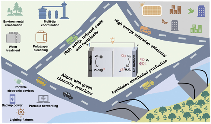
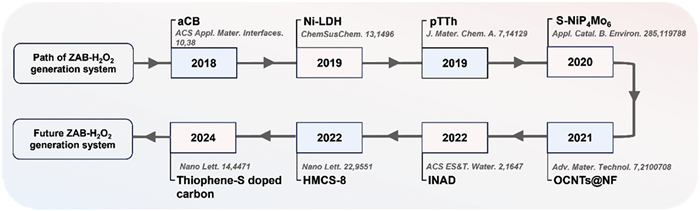
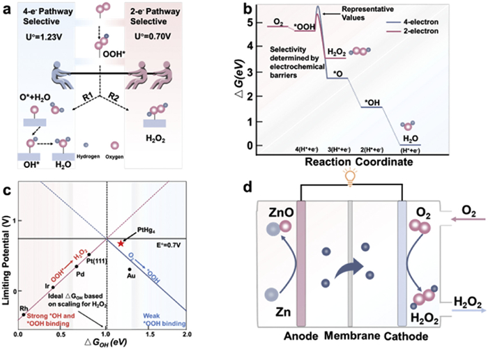
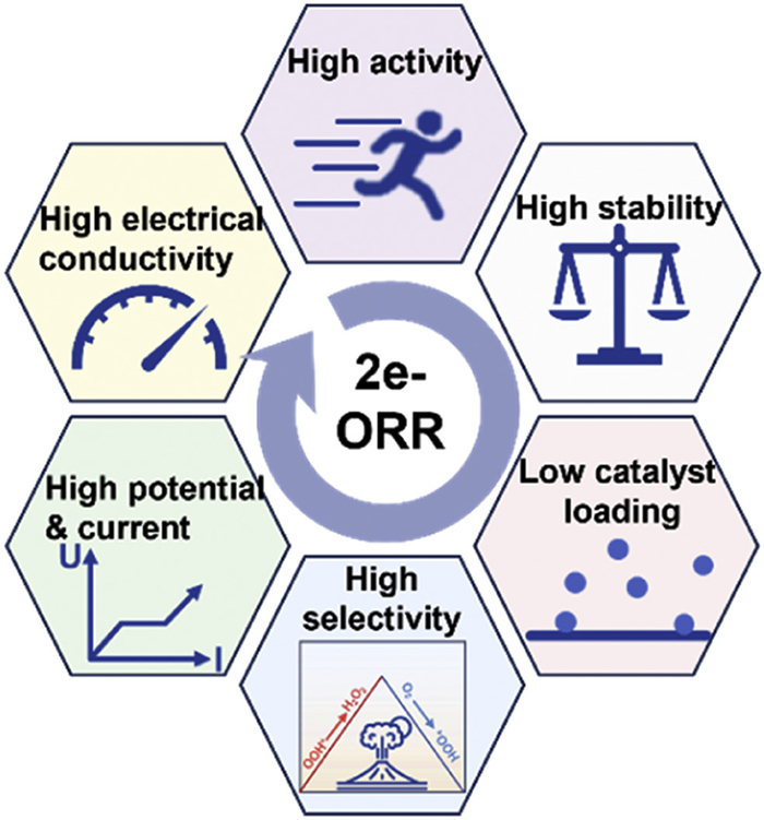
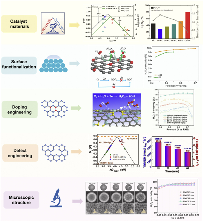
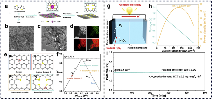
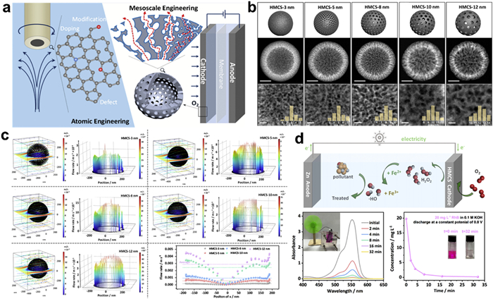
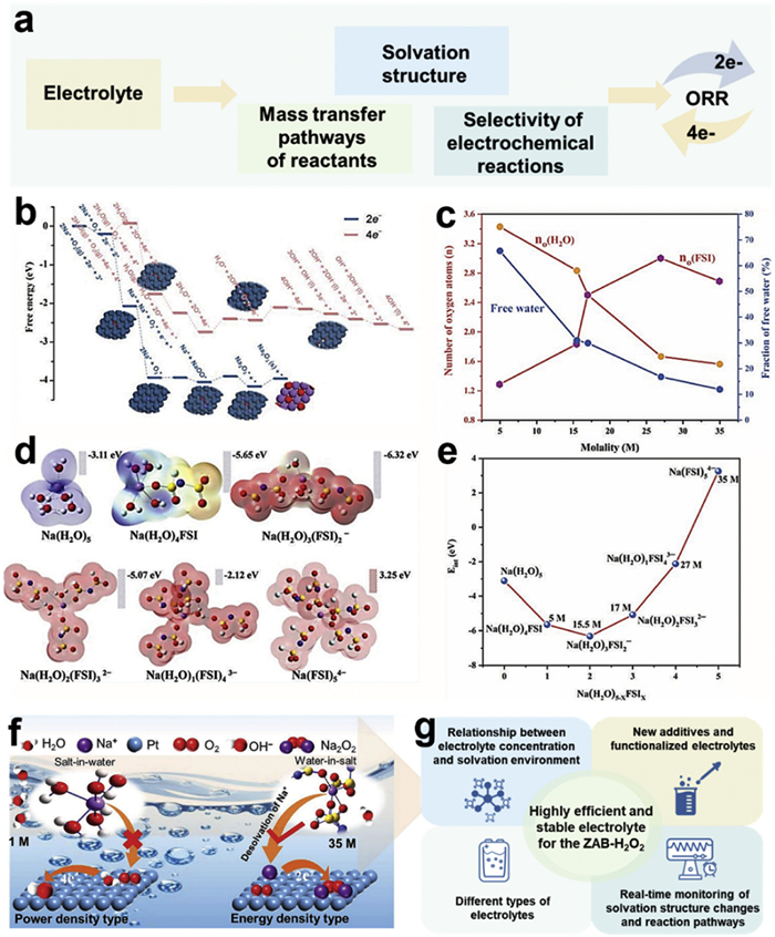
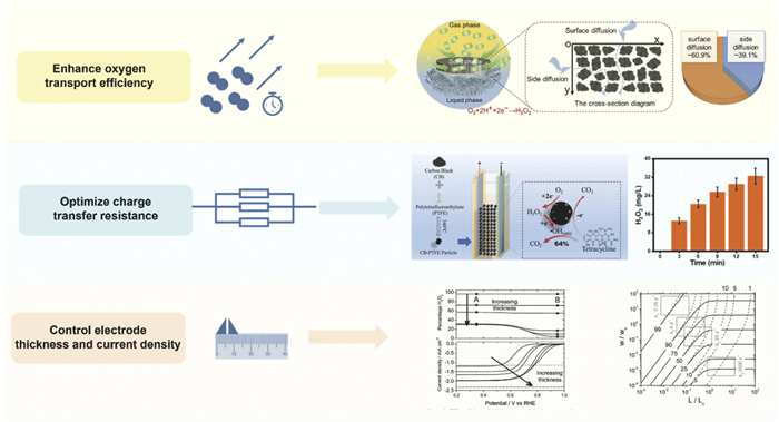
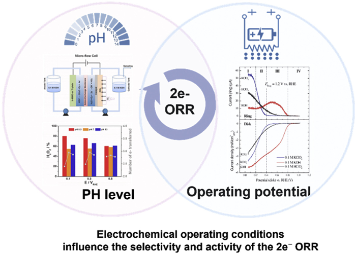
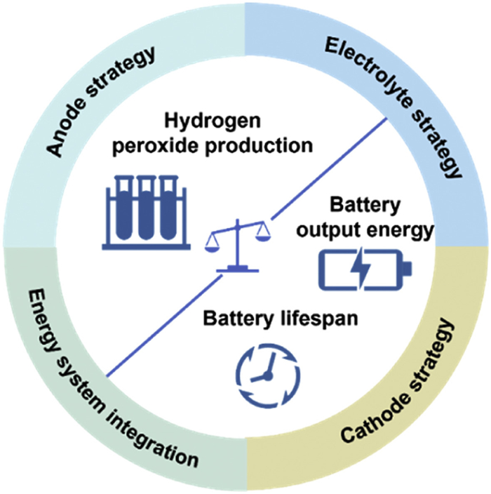
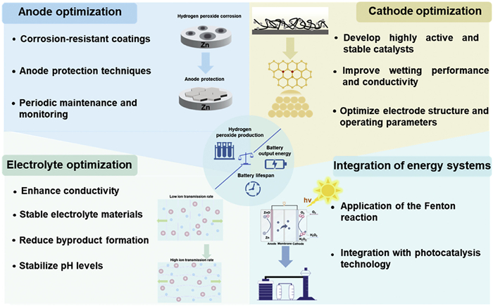
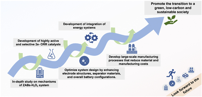


 扫一扫看文章
计量
- PDF下载量: 0
- 文章访问数: 11
- HTML全文浏览量: 1
 下载:
下载:
