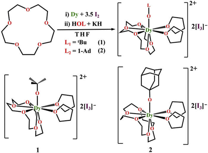
Scheme 1.
Synthetic routes for 1 and 2.
Pseudo-mono-coordinate dysprosium(Ⅲ)-alkoxide complexes exhibit enhanced magnetic axiality and blocking temperature
Wen-Jie Xu , Qian-Cheng Luo , Yang Fang , Chen-Jie Yuan , Jin-Tao Lu , Yuan-Qi Zhai , Yu Wang , Yan-Zhen Zheng

Single-molecule magnets (SMMs) have attracted much attention to scientists working in the fields of chemistry, physics and materials science since the first appearance [1], owing to the potential applications in high density data storage [2,3], molecular spintronics [4,5] and quantum information processing [6–8]. In this context, the enhancement of effective energy barrier (Ueff) to magnetization reversal and blocking temperature (TB) is the prerequisite. Notable progress has been achieved with lanthanide complexes, particularly for Dy(Ⅲ) based complexes, owing to the large magnetic anisotropy derived from the 6H15/2 ground-state term with large orbital momentum [9–11]. However, such a ground term has to be splitted by axial crystal field in order to maximize the magnetic anisotropy. Thus, two types of ligands are shown to exert such effect. The first one is cyclopentadienyl (Cp) based ligands which uses the η5-pentadentate coordination mode to sandwich the central Dy(Ⅲ) ions. The Cpcent–Dy–Cpcent bending usually determines the axiality of the complexes [12–21]. Hence, bulky substituted Cp ligands demonstrate higher Ueff and TB of these complexes [21]. In contrast, the second family which has more straight coordination mode of L–Dy–L and pseudo-Dnh local symmetry depending on the coordination number of the equatorial ligands [22–36]. Such a family could be termed as “the pseudo-two-coordinate family”, in which the [Dy(18-C-6)(1-AdO)2][I3] complex exhibits a benchmark Ueff of 2437(19) K [36].
In addition to the pseudo-two-coordination model, mono-coordinate Dy(Ⅲ) complexes are also effective to enhance Ueff. The extreme case is the gas type [DyO]+ model cation with a Dy-O bond length of only 1.74 Å, and its Ueff was predicted to be larger than 3000 K [37]. However, in reality [DyO]+ is not isolable and only those with “pseudo-mono-coordinate” Dy(Ⅲ) complexes are designable. In this context, several pseudo-mono-coordinate Dy(Ⅲ) complexes with axial Dy–F/N/O bonds have been reported (Table S1 in Supporting information) [38–42]. The complex [Dy(Tppy)F(dioxane)](PF6) bearing single of Dy–F bond exhibits Ueff exceeding 600 K [38]. Constructing Dy–N complexes requires bulky group-substituted imidazoline-2-imino ligands (ImRN–) obtained through complex multi-step organic synthesis, and these complexes exhibit excellent SMM performance with high Ueff of 1237 K and hysteresis loop opening temperatures up to 14 K [41]. As for the Dy–O complexes, Zhang et al. first reported two compounds [Dy(BPA-TPA)(CH3O/PhO)](BPh4)2·nCH2Cl2 using a bulky heptadentate [2,6-bis[bis(2-pyridylmethyl)amino]methyl]-pyridine (BPA-TPA) ligand to enwrap the Dy(Ⅲ) ion and choosing CH3O– and PhO– as axial strong field donors, exhibiting Ueff of 686 K and 469 K respectively and hysteresis loop opening temperatures up to 8 K [42].
To further enhance the magnetic axiality of Dy–O complexes, we perceived the stronger electron donors on the axial position and the weaker ancillary ligands are necessary. The previous work shown that ether type ligands are perfectly weak field equatorial ligands while alkoxides are suitable for enhancing the axiality [36,43–45]. Hence, we used this strategy to construct two “pseudo-mono-coordinate” Dy(Ⅲ) complexes, [Dy(OtBu)(15-C-5)(THF)2][I3]2 1 and [Dy(1-AdO)(15-C-5)(THF)2][I3]2 2. Complexes 1 and 2 display the desired pseudo-mono-coordinate model with very strong axial Dy–Oalkoxide bonding interaction and weak Dy–Oether bonds. As such both complexes exhibit enhanced SMM performance (Ueff = 1054(6) K, TBhys = 14 K, TBZFC = 8 K for 1; Ueff = 1028(9) K, TBhys = 10 K, TBZFC = 7 K for 2). Moreover, applying a 1 kOe field, the quantum tunneling of magnetization (QTM) process was effectively suppressed, and the relaxation times of 1 and 2 at 2 K increased by four orders of magnitude to 1216(10) s and 2368(13) s, respectively. Such results verifies the efficacy of the “pseudo-mono-coordinate” strategy to strengthen the SMM performance of Dy(Ⅲ) complexes.
Crystals of 1 and 2 were grown by reacting 1 equiv. of metallic dysprosium, 3.5 equiv. of iodine (I2), and 1 equiv. of KOtBu or KO(1-Ad) in the presence of 15-C-5 (1 equiv.) in tetrahydrofuran (THF), followed by slow diffusion in THF/hexane (1:3) solution at room temperature (Scheme 1). The composition and molecular structures of 1 and 2 were identified by elemental analysis, infrared spectrum, and single crystal X-ray diffraction characterization (Supporting information).
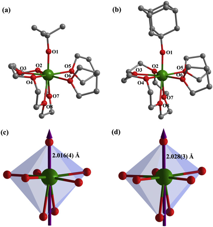
Though 1 and 2 share the similar [Dy(OL)(15-C-5)(THF)2]2+ cationic components and two triiodide [I3]− counterions they crystallize in different space groups. For 1 the complex crystallizes in the orthorhombic P212121, which is chiral. For 2 it crystallizes in a more common monoclinic space group P21/n (for detail, see Table S2 in Supporting information). We attribute this difference to the rotating feature of the tert‑butyl group which may give additional helical element into the molecular crystal of 1 [46,47]. In addition to this difference the Dy(Ⅲ) ions are both coordinated by a total of eight oxygen atoms, one from the alkoxides and seven from ancillary ligands, namely the η5-chelating 15-crown-5 and two monodentate tetrahydrofuran molecules (Figs. 1a and b). The Dy–Oalkoxide bond lengths are very short, namely 2.016(4) Å for 1 and 2.028(3) Å for 2 (Tables S3 and S4 in Supporting information), which are among the shortest up to date compared to other known dysprosium(Ⅲ) complexes [43–45,48,49]. The slightly longer Dy–Oalkoxide bond of 2 is attributed to the slightly larger steric hindrance of 1-AdO−. In contrast, the coordination of ether type ligands shows much longer Dy–Oether bond lengths ranging from 2.427(4) Å to 2.523(4) Å and from 2.416(3) Å to 2.509(3) Å for 1 and 2, respectively. As such, the central Dy(Ⅲ) ions are experiencing virtually a mono-coordinate crystal field as the negative charges are mainly focused on the alkoxides. Hence, both 1 and 2 are can be magnetically perceived as pseudo-mono-coordinate. As such, their ground energy splitting must be very similar to the diatomic model complex [DyO]+ [37]. The shortest intermolecular Dy···Dy distances are 9.954(1) Å and 10.178(1) Å for 1 and 2, respectively (Figs. S1 and S2 in Supporting information).
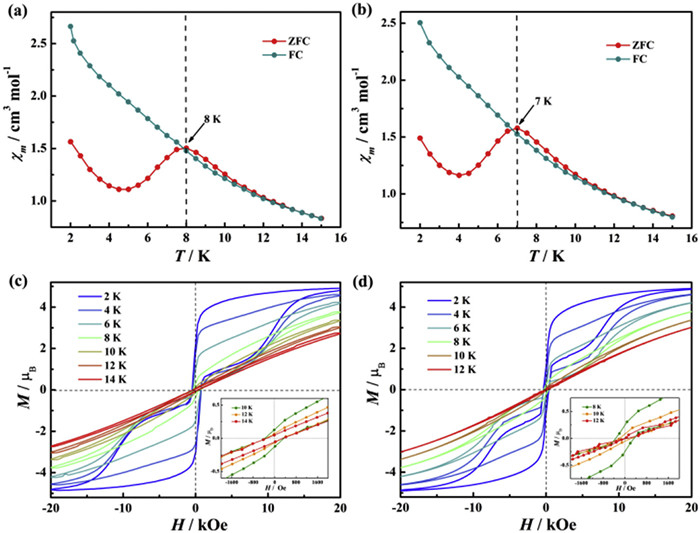
Variable-temperature direct current (dc) susceptibility data were conducted under a 2 kOe field from 300 K to 2 K. At 300 K, the χmT values are 14.06 and 14.14 cm3 K/mol for 1 and 2, respectively (Figs. S3 and S4 in Supporting information), aligning well with the theoretical values of 14.17 cm3 K/mol for the free Dy(Ⅲ) ion (4f9, 6H15/2, S = 5/2, L = 5, g = 4/3). Upon cooling, the χmT values for both decreases slowly down to 12 K, followed by a sharp drop to 6.09 and 7.01 cm3 K/mol at 2 K, suggesting the presence of magnetic blocking at low temperature. Zero-field-cooled (ZFC) and field-cooled (FC) magnetic susceptibility were measured under 2 kOe field at 3 K/min. The ZFC–FC plots distinctly exhibit ZFC peaks at 8 K and 7 K for 1 and 2, respectively (Figs. 2a and b). With a sweep rate of 200 Oe/s, magnetic hysteresis behavior were then investigated, and the butterfly-shaped hysteresis loops remain open up to 14 K and 10 K for 1 and 2, respectively, indicating non-negligible QTM in the low-temperature region at zero field (Figs. 2c and d). The somewhat higher blocking temperature of 1 than 2 is mainly attributed to the shorter Dy–Oalkoxide bond. Meanwhile, the field (H) dependent magnetization (M) data were measured at 2−10 K from 0 to 50 kOe and the results reveal that the maximum M values are 5.10 and 5.13 µB at 50 kOe for 1 and 2, respectively (Figs. S5 and S6 in Supporting information). In addition, the significant separations between the isofield curves in the reduced magnetization plots further demonstrate the presence of magnetic anisotropy.
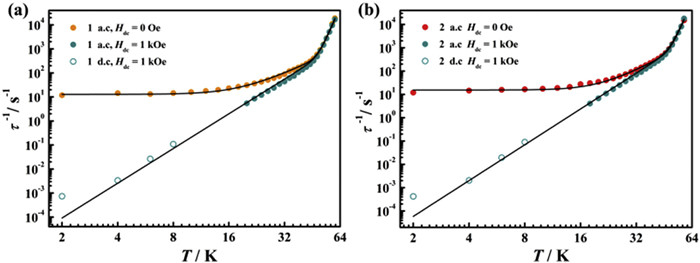
Variable-frequency alternating current (ac) susceptibilities of 1 and 2 were measured in the zero field to probe the dynamic magnetic relaxation behavior (Figs. S7 and S8 in Supporting information). The pronounced frequency-dependent peaks of the out-of-phase (χ’’) ac susceptibility revealed characteristic signatures of SMMs, with well-defined maximum peak temperature (1000 Hz) of 58 K for 1 and 56 K for 2. Temperature-dependent relaxation times were extracted by fitting the Cole−Cole plots of χ’’ vs. χ’ with the generalized Debye model (Figs. S9 and S10, Tables S5 and S6 in Supporting information). The log-log plots of τ−1 versus T for 1 and 2 show three diverse correlations under zero external field (Fig. 3), corresponding to the temperature-dependent Orbach and Raman process as well as the temperature-independent QTM process. Consequently, these data can be fitted using the following equation.
|
|
(1) |
The best fitting parameters are Ueff = 1054(6) K,
 DownLoad:
CSV
DownLoad:
CSV
| Complex | Ueff (K) | τ0 (s) | C (s–1 K–n) | n | τQTM (s) |
| 1 (0 Oe) | 1054(6) | 1.31(2) × 10–12 | 4.87(4) × 10–4 | 3.5(2) | 0.078(1) |
| 1 (1 kOe) | 1054(7) | 1.50(3) × 10–12 | 3.31(2) × 10–6 | 4.8(2) | / |
| 2 (0 Oe) | 1028(9) | 1.43(3) × 10–12 | 6.92(3) × 10–5 | 4.1(1) | 0.065(2) |
| 2 (1 kOe) | 1028(11) | 1.03(4) × 10–12 | 1.72(2) × 10–6 | 5.1(1) | / |
Obviously, complexes 1 and 2 exhibit pronounced magnetic anisotropy, as evidenced by their Ueff values surpassing 1000 K. The comparatively higher Ueff value for 1 stems from the shorter axial Dy–Oalkoxide bond. Nevertheless, the τQTM values <0.1 s indicate that high Ueff values do not afford them long relaxation times at low temperatures as expected, due to the significant impact of severe QTM.
Moreover, we implemented field-dependent ac susceptibility measurements from 0 to 3 kOe at 30 K and obtained 1 kOe as the optimal external field for mitigating QTM (Fig. S11 in Supporting information). Under this applied field, we used ac susceptibility at higher temperatures to compile relaxation times (Figs. S12 and S13, Tables S7 and S8 in Supporting information). As the temperature decreases, the relaxation times progressively elongated, surpassing the detection threshold of the ac susceptibility measurements. Consequently, we used low-temperature dc magnetization decay measurements, from which relaxation times can be extracted by fitting the data to a stretched exponential function (Figs. S14 and S15, Tables S9 and S10 in Supporting information). We found that high-temperature relaxation times remained constant and low-temperature relaxation times were significantly prolonged (Fig. 3). At 2 K, the relaxation times of 1 and 2 are 1216(10) and 2368(13) s, respectively. These are about four orders of magnitude longer than those at zero field. Only considering the Orbach and Raman processes in Eq. 1, the best fits are also shown in Table 1. It is obvious that the presence of the optimal field does not affect the Orbach process while effectively suppressing the fast relaxation process.
To gain insight into the relaxation mechanism of 1 and 2, complete-active-space self-consistent-field spin-orbit (CASSCF-SO) calculations were performed by Orca 5.0 program [50]. The geometries utilized in the calculations were directly extracted from their single crystal data without optimization. As expected, such crystal field environment affords the large energy splittings of 1213 and 1203 K for 1 and 2 which are originated from the ground term 6H15/2 (Tables S11 and S12 in Supporting information). The ground Kramers doublet (KD) of them exhibits very strong magnetic axiality that its g tensors approach the Ising limit with gx = gy = 0, gz = 19.97 and corresponding wavefunction is composed of pure |±15/2> state. As shown in Figs. 1c and d, the calculated principal magnetic axes for the ground KD of Dy(Ⅲ) ion are both along the direction of axial Dy–Oalkoxide in 1 and 2, also verifying their uniaxial magnetic anisotropy. Then the electrostatic potential (ESP) from all coordinated O atoms was calculated based on Mulliken atomic charge (MAC) and corresponding Dy–O bond length (Table S13 in Supporting information). In terms of all similar MACs, it is evident that the ESP of oxygen atom on the alkoxide is largest which can be attributed to the shortest Dy–O distance. This result proves that the strong magnetic axiality in both complexes origins from the axial Dy–Oalkoxide coordination mode.
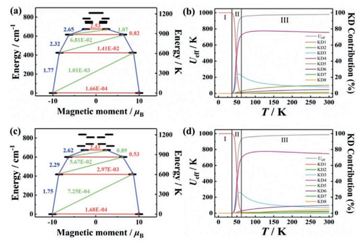
For the first excited KD in 1 and 2, it is located at 611 and 602 K higher than the corresponding ground KD, and can be well described as mJ = |±13/2>. From the second excited KD on, the wavefunctions exhibit the admixture characteristic, together with the relatively large deviation angle of magnetic anisotropy axes relative to the ground KD (Tables S11 and S12). Additionally, the possible magnetic relaxation pathways were depicted in Figs. 4a and c, the transition magnetic moments of ~10–4 µB between the ground KD is small enough which guarantees the zero-field SMM behaviour for 1 and 2. Then reliable theoretical Ueff for both complexes were predicted by considering the thermal populations of tunneling rates for each KD based on Eqs. 2-4 [51,52]. ki represents the demagnetization rate for each KD, and Ei refers to their relative energy height, while kQT,i is the tunneling rates within each KD where gx, gy and gz are corresponding Landé factors. As shown in Figs. 4b and d, the calculated Ueff and relaxation contributions from various KDs are temperature dependent in the whole temperature regime which can be evidently segmented into three regions. For region Ⅰ, QTM within the ground KD dominates in the whole magnetic relaxation, affording the Ueff very close to zero. With the increment of temperature, the contributions of the ground KD decreases rapidly in region Ⅱ while the ones for other excited KDs rise and get prominent, especially KD3 and KD4, which leads to the Ueff growing remarkably. In region Ⅲ, Orbach relaxation is fully activated and the Ueff also becomes constant, together with the most relaxation contribution from KD4. Ultimately, the predicted saturation Ueff values for 1 and 2 are 980 and 987 K, which are agreement with the corresponding experimental ones.
|
|
(2) |
|
|
(3) |
|
|
(4) |
In summary, we used ether type neutral ligands, 15-crown-5 and tetrahydrofurans, in conjunction with very basic alkoxide ligands OtBu− and 1-AdO− to synthesize two pseudo-mono-coordinate Dy(Ⅲ) complexes, which show SMM behaviour with high Ueff value exceeding 1000 K and opened magnetic hysteresis loops up to 14 K. Therefore, this work provides a new pseudo-mono-coordinate strategy to construct Dy(Ⅲ)-alkoxide complexes with high SMM performance.
The authors declare that they have no known competing financial interests or personal relationships that could have appeared to influence the work reported in this paper.
Wen-Jie Xu: Writing – original draft, Methodology, Formal analysis, Data curation. Qian-Cheng Luo: Software, Formal analysis, Data curation. Yang Fang: Data curation. Chen-Jie Yuan: Data curation. Jin-Tao Lu: Validation, Data curation. Yuan-Qi Zhai: Writing – review & editing, Supervision, Data curation. Yu Wang: Validation, Data curation. Yan-Zhen Zheng: Writing – review & editing, Supervision, Project administration, Funding acquisition.
This work was supported by the National Natural Science Foundation of China (Nos. 22375157, 52471016), the Medical-Engineering Cross Project of the First Affiliated Hospital of XJTU (No. QYJC02), Key Scientific and Technological Innovation Team of Shaanxi Province (No. 2020TD-001), State Key Laboratory of Electrical Insulation and Power Equipment (No. EIPE23405), Key Laboratory Construction Program of Xi’an Municipal Bureau of Science and Technology, and the Fundamental Research Funds for Central Universities (Nos. xtr052023002 and xzy012024057), “Scientists engineers” Team Building Project of Qin Chuang Yuan in Shaanxi Province of China (No. 2022KXJ-088) and the Programme of Introducing Talents of Discipline to Universities (No. B23025). We also thank the Instrument Analysis Center of Xi’an Jiaotong University.
Supplementary material associated with this article can be found, in the online version, at doi:
R. Sessoli, D. Gatteschi, A. Caneschi, M.A. Novak, Nature 365 (1993) 141–143. doi: 10.1038/365141a0
F.D. Natterer, W. Paul K. Yang, et al., Nature 543 (2017) 226–228. doi: 10.1038/nature21371
R. Sessoli, Nature 543 (2017) 189–190. doi: 10.1038/543189a
L. Bogani, W. Wernsdorfer, Nat. Mater. 7 (2008) 179–186. doi: 10.1038/nmat2133
S. Sanvito, Chem. Soc. Rev. 40 (2011) 3336–3355. doi: 10.1039/c1cs15047b
M.N. Leuenberger, D. Loss, Nature 410 (2001) 789–793. doi: 10.1038/35071024
A. Gaita-Ariño, F. Luis, S. Hill, E. Coronado, Nat. Chem. 11 (2019) 301–309. doi: 10.1038/s41557-019-0232-y
S. Thiele, F. Balestro, R. Ballou, et al., Science 344 (2014) 1135–1138. doi: 10.1126/science.1249802
J.L. Liu, Y.C. Chen, M.L. Tong, Chem. Soc. Rev. 47 (2018) 2431. doi: 10.1039/c7cs00266a
N.F. Chilton, Annu. Rev. Mater. Res. 52 (2022) 79–101. doi: 10.1146/annurev-matsci-081420-042553
V.S. Parmar, D.P. Mills, R.E.P. Winpenny, Chem. Eur. J. 27 (2021) 7625–7645. doi: 10.1002/chem.202100085
C.A.P. Goodwin, F. Ortu, D. Reta, N.F. Chilton, D.P. Mills, Nature 548 (2017) 439–442. doi: 10.1038/nature23447
F.S. Guo, B.M. Day, Y.C. Chen, et al., Angew. Chem. Int. Ed. 56 (2017) 11445–11449. doi: 10.1002/anie.201705426
K.R. McClain, C.A. Gould, K. Chakarawet, et al., Chem. Sci. 9 (2018) 8492–8503. doi: 10.1039/C8SC03907K
P.E. Evans, D. Reta, G.F.S. Whitehead, N.F. Chilton, D.P. Mills, J. Am. Chem. Soc. 141 (2019) 19935–19940. doi: 10.1021/jacs.9b11515
C.A. Gould, K.R. McClain, D. Reta, et al., Science 375 (2022) 198–202. doi: 10.1126/science.abl5470
J.C. Vanjak, B.O. Wilkins, V. Vieru, et al., J. Am. Chem. Soc. 144 (2022) 17743–17747. doi: 10.1021/jacs.2c06698
A.H. Vincent, Y.L. Whyatt, N.F. Chilton, J.R. Long, J. Am. Chem. Soc. 145 (2023) 1572–1579. doi: 10.1021/jacs.2c08568
G.K. Gransbury, S.C. Corner, J.G.C. Kragskow, et al., J. Am. Chem. Soc. 145 (2023) 22814–22825. doi: 10.1021/jacs.3c08841
Y.D. Wang, Q.C. Luo, Y.Z. Zheng, Angew. Chem. Int. Ed. 63 (2024) e202407016. doi: 10.1002/anie.202407016
F.S. Guo, B.M. Day, Y.C. Chen, M.L. Tong, Science 362 (2018) 1400–1403. doi: 10.1126/science.aav0652
J. Liu, Y.C. Chen, J.L. Liu, et al., J. Am. Chem. Soc. 138 (2016) 5441–5450. doi: 10.1021/jacs.6b02638
Y.S. Ding, N.F. Chilton, R.E. Winpenny, Y.Z. Zheng, Angew. Chem. Int. Ed. 55 (2016) 16071–16074. doi: 10.1002/anie.201609685
K.X. Yu, J.G.C. Kragskow, Y.S. Ding, et al., Chem 6 (2020) 1777–1793. doi: 10.1016/j.chempr.2020.04.024
X.L. Ding, Q.C. Luo, Y.Q. Zhai, et al., Chin. J. Chem. 40 (2022) 563–570. doi: 10.1002/cjoc.202100722
Y. Ma, Y.Q. Zhai, Q.C. Luo, Y.S. Ding, Y.Z. Zheng, Angew. Chem. Int. Ed. 61 (2022) e202206022. doi: 10.1002/anie.202206022
Q.C. Luo, Y.Z. Zheng, Trends Chem. 5 (2023) 869–872. doi: 10.1016/j.trechm.2023.10.004
X.L. Ding, Y.Q. Zhai, T. Han, et al., Chem. Eur. J. 27 (2021) 2623–2627. doi: 10.1002/chem.202003931
Z.H. Li, Y.Q. Zhai, W.P. Chen, Y.S. Ding, Y.Z. Zheng, Chem. Eur. J. 25 (2019) 16219–16224. doi: 10.1002/chem.201904325
Z.H. Zhu, C. Zhao, T.T. Feng, et al., J. Am. Chem. Soc. 143 (2021) 10077–10082. doi: 10.1021/jacs.1c05279
A.B. Canaj, S. Dey, C. Wilson, et al., Chem. Commun. 56 (2020) 12037–12040. doi: 10.1039/d0cc04559d
Z.H. Zhu, C. Zhao, Q. Zhou, et al., CCS Chem. 4 (2022) 3762–3771. doi: 10.31635/ccschem.022.202101604
S.T. Liu, Y. Gil, C. Zhao, et al., Inorg. Chem. Front. 9 (2022) 4982–4989. doi: 10.1039/d2qi01565j
S.K. Gupta, S. Dey, T. Rajeshkumar, G. Rajaraman, R. Murugavel, Chem. Eur. J. 28 (2022) e202103585. doi: 10.1002/chem.202103585
X. Zhong, D.Y. Li, C. Cao, et al., Inorg. Chem. 63 (2024) 21909–21918. doi: 10.1021/acs.inorgchem.4c03012
W.J. Xu, Q.C. Luo, Z.H. Li, Y.Q. Zhai, Y.Z. Zheng, Adv. Sci. 11 (2024) 2308548. doi: 10.1002/advs.202308548
L. Ungur, L.F. Chibotaru, Phys. Chem. Chem. Phys. 13 (2011) 20086–20090. doi: 10.1039/c1cp22689d
L. Norel, L.E. Darago, B.L. Guennic, et al., Angew. Chem. Int. Ed. 57 (2018) 1933–1938. doi: 10.1002/anie.201712139
A.B. Canaj, M.K. Singh, E.R. Marti, et al., Chem. Commun. 55 (2019) 5950–5953. doi: 10.1039/c9cc00965e
B.K. Ling, Y.Q. Zhai, J. Han, T. Han, Y.Z. Zheng, Dalton Trans. 49 (2020) 6969–6973. doi: 10.1039/d0dt01146k
R. Sun, C.Y. Li, Z.N. Huang, et al., CCS Chem. 7 (2025) 2054–2064. doi: 10.31635/ccschem.024.202404701
B. Zhang, Z.J. Cheng, Y.Y. Wu, et al., Chem. Sci. 13 (2022) 13231–13240. doi: 10.1039/d2sc03182e
Y.S. Ding, W.J.A. Blackmore, Y.Q. Zhai, et al., Inorg. Chem. 61 (2022) 227–235. doi: 10.1021/acs.inorgchem.1c02779
Y.S. Ding, T. Han, Y.Q. Zhai, et al., Chem. Eur. J. 26 (2020) 5893–5902. doi: 10.1002/chem.202000646
Y.S. Ding, K.X. Yu, D. Reta, et al., Nat. Commun. 9 (2018) 3134. doi: 10.1038/s41467-018-05587-6
M. Nespolo, A.H. Benahsene, J. Appl. Cryst. 54 (2021) 1594–1599. doi: 10.1107/s1600576721009109
A. Matsumoto, S. Takeda, S. Harada, K. Soai, Tetrahedron 27 (2016) 943–946. doi: 10.1016/j.tetasy.2016.07.013
Q.C. Luo, X.L. Ding, W.J. Xu, Y.Q. Zhai, Y.Z. Zheng, Chin. Chem. Lett. 36 (2025) 110304. doi: 10.1016/j.cclet.2024.110304
W. Yang, G. Velkos, F.P. Liu, et al., Adv. Sci. 6 (2019) 1901352. doi: 10.1002/advs.201901352
F. Neese, Comput. Mol. Sci. 12 (2022) e1606. doi: 10.1002/wcms.1606
D. Aravena, J. Phys. Chem. Lett. 9 (2018) 5327–5333. doi: 10.1021/acs.jpclett.8b02359
B. Yin, C.C. Li, Phys. Chem. Chem. Phys. 22 (2020) 9923–9933. doi: 10.1039/d0cp00933d

Figure 1 Crystal structures for the [Dy(OL)(15-C-5)(THF)2]2+ cations in (a) 1 and (b) 2. Side views of coordination polyhedra and calculated principal magnetic axes (depicted with purple arrow) for the ground doublet of Dy(Ⅲ) ion in (c) 1 and (d) 2. Colour codes: Dy, green; O, red and C, gray. All hydrogen atoms are omitted for clarity.

Figure 2 Field-cooled (FC, dark cyan) and zero-field-cooled (ZFC, red) variable-temperature magnetic susceptibility for (a) 1 and (b) 2 under an applied field of 2 kOe from 2 K to 15 K (3 K/min). Magnetic hysteresis loops for (c) 1 and (d) 2 with an average sweep rate of 200 Oe/s. Insert: Magnification of hysteresis loops at selected temperatures.

Figure 3 Plots of natural log of τ−1 vs. T for (a) 1 and (b) 2 in zero and 1 kOe field. The solid lines are the best fits.

Figure 4 Left: Ab initio calculated possible magnetic relaxation path diagrams for (a) 1 and (c) 2. The horizontal red arrows represent the QTM/TA-QTM processes, while the non-horizontal ones show the spin-phonon transition paths. The numbers next to the arrows are averaged transition magnetic moments ((|µX|+|µY|+|µZ|)/3) in µB between the connecting pairs. Right: Predicted Ueff (black dotted lines) and relaxation contributions from various KDs (coloured solid lines) for (b) 1 and (d) 2.
Table 1. Fitting parameters for 1 and 2 at zero and 1 kOe field.
| Complex | Ueff (K) | τ0 (s) | C (s–1 K–n) | n | τQTM (s) |
| 1 (0 Oe) | 1054(6) | 1.31(2) × 10–12 | 4.87(4) × 10–4 | 3.5(2) | 0.078(1) |
| 1 (1 kOe) | 1054(7) | 1.50(3) × 10–12 | 3.31(2) × 10–6 | 4.8(2) | / |
| 2 (0 Oe) | 1028(9) | 1.43(3) × 10–12 | 6.92(3) × 10–5 | 4.1(1) | 0.065(2) |
| 2 (1 kOe) | 1028(11) | 1.03(4) × 10–12 | 1.72(2) × 10–6 | 5.1(1) | / |
 下载: 导出CSV

 扫一扫看文章

扫一扫关注我们

 下载:
下载: