Received Date:
22 November 2024 Accepted Date:
12 February 2025 Revised Date:
19 January 2025 Available Online:
15 May 2026
Abstract:
High-performance electrode materials are of paramount significance for practical applications in energy storage devices, and the design of hollow-structured active electrode materials is a simple effective strategy. Herin, a three-dimensional nickel cobalt cadmium ternary sulfide hollow nanoprism material (NiCoCd-S) was successfully synthesized by combination of refluxing, hydrothermal and calcination methods. The co-existence and synergism of Ni, Co and Cd endow the material surface with abundant catalytic active sites, facilitating the progress of the reaction, enabling it to exhibit better performance than single-metal or bimetallic compounds. The unique hollow structure facilitates increased contact between the electrolyte and more electroactive sites, while the shorter diffusion pathways enable rapid ion/electron transfer rates within the material, synergistically generating enhanced supercapacitive activity. The synthesized NiCoCd-S shows a high specific capacitance (Cg) of 1643.7 F/g@1 A/g, along with a prolonged cycling life (81.6% capacitance retention after 10,000 cycles). When assembling the NiCoCd-S//AC asymmetric supercapacitor, it demonstrates an impressive energy/power density of 105.9 Wh/kg and 919.2 W/kg, respectively. After 10,000 charging-discharging cycles, the initial capacitance can still be maintained at 88.5%. The present work offers a strategy for the rational design of hollow nanostructured polymetallic sulfides with high electrochemical performance and stability.
Supercapacitors (SCs), as a novel and promising energy storage device, have garnered significant attention in recent years due to their high power density (P), rapid charge-discharge capabilities, outstanding cycling stability and electrochemical reversibility [1-5]. However, to achieve widespread adoption of supercapacitors, the obstacle of low energy density (E) must be overcome [6]. The energy density formula (1/2CV2) indicates that increasing the energy density of supercapacitors can be achieved by raising the voltage or the capacitance [7-9]. The selection of electrode materials with excellent performance is considered one of the most crucial pathways to enhance the relatively low E of supercapacitors and achieve their commercialization [10]. Many transition metal oxide/hydroxide-based materials have attracted attention [11], such as N–NiCoO [12], NiCo2O4 [13], CoMn2O4/C [14], but these materials exhibit poor conductivity, leading to subpar supercapacitor performance. Therefore, efforts are being made to enhance conductivity by replacing these oxides/hydroxides with sulfides that exhibit significantly improved electrical and electrochemical properties [7,15]. Various metal sulfide-based materials, including NiCo2S4/Co3S4 [16], r-NiCo2S4 [17], MCo3-xS4 (M = Ni, Mn, Zn) [18], have been investigated for application as supercapacitor electrode materials.
Previous research has indicated that mixed-metal sulfides, as electrode active materials, exhibit significant merits compared to single-metal materials because of their abundant redox active sites, splendid conductivity, and unique synergistic effects [19]. Hence, researchers have extensively investigated hybrid materials with unique three-dimensional structures and excellent theoretical capacitance to further enhance their electrochemical performance. For example, Ni et al. [20] prepared a composite material of Mn-Ni-Co sulfides with a double-layer hollow cage-like construction through ion etching and hydrothermal sulfidation. This material exhibited a Cg of 2460 F/g@1 A/g. A hybrid supercapacitor device assembled using Mn-Ni-Co sulfide cathode and carbon anode demonstrated high E of 80.4 Wh/kg at 800 W/kg and excellent long-term cycling performance with 78.5% capacitance retention after 10,000 cycles. Jia et al. [21] synthesized amorphous nanosheets and bidentate ligand-modified hierarchical nickel-cobalt hydroxide sulfide hollow spheres (NiCo-DHS) through the hydrolysis of self-templated metal alkoxide followed by a room-temperature anion exchange process. This material exhibited a high Cg of 973.6 C/g@1 A/g and excellent stability (only 7.4% capacity loss after 8000 cycles at 10 A/g). A hybrid device assembled with this material and porous activated carbon provided an E of 65.91 Wh/kg at a P of 0.89 kW/kg and displayed remarkable cycling stability. However, there is still an urgent need to explore new materials with unique nanoscale structures to further enhance the performance of these electrodes.
Due to the significant influence of the structural and morphological characteristics of active materials on the electrochemical energy storage of supercapacitors, materials with unique nanoscale structures are of increasing interest. Advantages of materials with distinct nanoscale structures, including high surface area and inner cavities, have led to a growing interest in hollow/porous structure materials with appropriate composition and desired shapes. Designing active electrode materials with hollow structures is a simple effective strategy. Hollow shells can reduce nanoparticle aggregation within the material and accommodate volume expansion during charge-discharge processes, thereby enhancing the material’s cycling stability [22,23]. It is worth noting that three-dimensional hollow materials have demonstrated significant advantages in the field of energy storage. Their benefits include high specific surface area, enabling increased electrode/electrolyte contact area, and facilitating easier ion penetration, thus generating more redox-active channels to enhance charge storage [7]. Furthermore, the hollow structure can reduce material pulverization, minimize shape deformation, and accommodate volume changes to the maximum extent, thereby enhancing the material’s long-term cycling stability.
In this study, we propose an effective strategy for the synthesis of three-dimensional hollow nanoprismatic NiCoCd ternary metal sulfide materials from transition metal acetates and evaluate their performance as supercapacitor electrode materials. We initially synthesized solid nanoprismatic materials through a co-precipitation strategy using refluxing, followed by ion-exchange sulfidation through hydrothermal treatment to form hollow nanoprismatic ternary metal sulfides. Subsequently, we enhanced the crystalline properties of the hollow nanoprismatic ternary metal sulfides through annealing in an argon atmosphere. The resulting hollow nanoprismatic NiCoCd-S exhibited excellent supercapacitor performance. On account of the synergistic effects between different components and the three-dimensional hollow nanoprismatic structure of the electrode material, NiCoCd-S exhibited a high Cg (1643 F/g at 1 A/g), surpassing that of NiCo-S. Finally, the NiCoCd-S//AC supercapacitor assembled with NiCoCd-S as the positive electrode achieved a high E of 105.89 Wh/kg; even at a high P of 7473.61 W/kg, its E remained at 62.7 Wh/kg. Under a current density of 10 A/g, after 10,000 cycles, the capacitance of the NiCoCd-S//AC supercapacitor still retained 88.5%, demonstrating outstanding cycling stability. The research results exhibit that the NiCoCd-S nanoprismatic electrode material possesses excellent electrochemical performance, offering promising prospects in the field of supercapacitor electrodes.
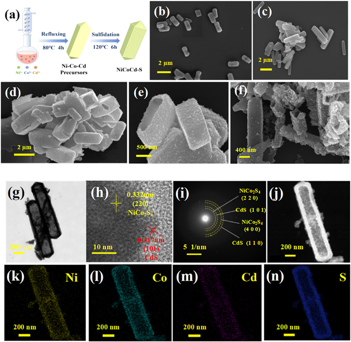
The schematic diagram of NiCoCd-S synthesis is displayed in Fig. 1a. First, the acetates of nickel, cobalt and cadmium were refluxed in ethanol, and through OH- ion exchange, solid rod-shaped ternary metal hydroxide materials were formed. TEM characterization of the NiCoCd-Precursors material is exhibited in Fig. S1 (Supporting information). The obtained ternary metal hydroxides were subsequently sulfidized under hydrothermal conditions, during which sulfurization gradually replaced the OH- ions to form sulfides. The sulfides agglomerated on the surface, and internal ions migrated continuously to the interface, forming a distinctive hollow prismatic construction. Subsequently, the ternary metal sulfides with a hollow structure were successfully prepared by high-temperature annealing in an Ar atmosphere to improve their crystalline properties. The morphology and structure of the materials were studied using scanning electron microscopy (SEM) and transmission electron microscopy (TEM) techniques. SEM images indicate that the both NiCo and NiCoCd precursor have regular nanoprismatic morphologies (Figs. 1b and c). The NiCo precursor’s prisms are shorter and thicker, with a length of approximately 1 µm; while the NiCoCd precursor is more slender, with a length of about 2 µm. From the SEM images of the products, NiCo-S (Figs. 1d and e) and NiCoCd-S (Fig. 1f), it can be observed that sulfidation can etch the center of the precursors, resulting in hollow prismatic NiCo-S and NiCoCd-S with rough surfaced. The hollow structure and rough surface facilitate the exposure of active sites and rapid mass transfer.
Figure 1
Figure 1.
(a) Schematic illustration for the preparation process of NiCoCd-S hollow nanoprisms. SEM images of (b) NiCo precursor, (c) NiCoCd precursor, (d, e) NiCo-S and (f) NiCoCd-S. (g) TEM images, (h) HRTEM images, (i) selected area electron diffraction (SAED), (j-n) the elemental mappings of NiCoCd-S.
TEM characterization of the NiCoCd-S material is exhibited in Figs. 1g–n. In Fig. 1g, the obtained NiCoCd-S has a unique hollow prismatic structure, consistent with the SEM images. The high-resolution TEM image in Fig. 1h gives more detailed lattice structure information of the NiCoCd-S sample. The lattice spacings marked in red are 0.317 nm, corresponding to the (101) plane of CdS, while those marked in yellow are 0.332 nm, corresponding to the (220) plane of NiCo2S4 [24]. Electron diffraction was performed on a single NiCoCd-S hollow nanoprism, and the results in Fig. 1i reveal its pronounced polycrystalline nature, with diffraction rings ascribed to the (220) and (400) planes of NiCo2S4 and the (101) and (110) planes of CdS [25]. Figs. 1j–n represent the elemental mapping images of the NiCoCd-S sample, demonstrating that the distribution of Ni, Co, Cd and S elements in the sample is higher at the edges than in the center, aligning with the hollow structure of the sample. This further confirms the successful synthesis of the hollow nanoprismatic NiCoCd-S.
To further investigate the crystalline structure and molecular composition of the products, X-ray diffraction (XRD) analysis was conducted. In Fig. S2 (Supporting information), both NiCo-S and NiCoCd-S exhibit distinct diffraction peaks at 2θ values of 26.8°, 31.5°, 38.3° and 55.3°, corresponding to the (220), (311), (400) and (440) crystal planes of NiCo2S4 (JCPDS No. 20–0782), respectively [26]. Due to the addition of Cd, diffraction peaks are appeared at 2θ = 25.2°, 28.2°, 36.5°, 43.5°, and 46.8°, ascribing to CdS (JCPDS No. 75–1545) crystal planes (100), (101), (102), (110) and (103), respectively. Additionally, the diffraction peak at 16.3° corresponding to the (111) plane of NiCo2S4 was exposed and shifted by 0.9° towards higher angles, possibly because of lattice distortion caused by the introduction of Cd [27].
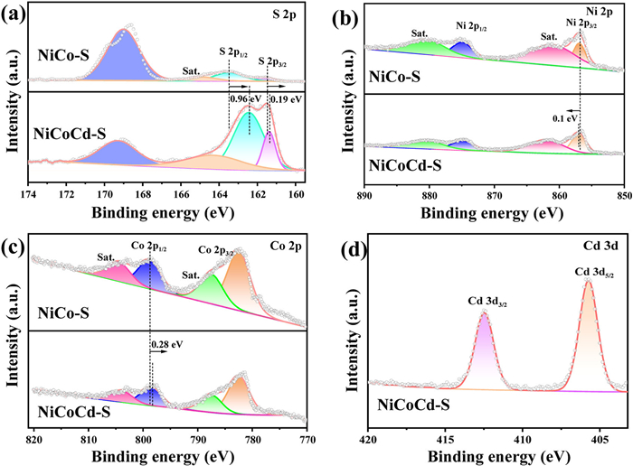
The surface elemental composition and electronic states of the hollow nanoprismatic NiCo-S and NiCoCd-S were investigated using X-ray photoelectron spectroscopy (XPS). In Fig. S3 (Supporting information), the XPS survey spectra of NiCoCd-S suggests the existence of Ni, Co, Cd and S, while NiCo-S contains elements Ni, Co and S, which is in accord with the EDS element mapping results. Fig. 2a depicts the high-resolution XPS spectrum of S 2p. It can be observed that NiCo-S exhibits two distinct peaks at 161.5 and 162.8 eV, ascribed to S 2p3/2 and S 2p1/2, respectively, suggesting the presence of S2-. Peaks at 169.0 and 164.8 eV are corresponded to S-O and satellite peaks, respectively. In contrast, NiCoCd-S displays weaker peaks at 161.9 and 163.4 eV, ascribed to S 2p3/2 and S 2p1/2, respectively, and they shifted to lower binding energy positions relative to NiCo-S, suggesting an interaction between Cd and NiCo-S. Fig. 2b represents the high-resolution XPS spectrum of Ni 2p. In the case of NiCo-S, two strong characteristic peaks were observed at ~857 and 874 eV, attributing to Ni 2p3/2 and Ni 2p1/2, respectively. The peaks fitted at 856.9 and 874.9 eV can be corresponded to Ni2+, while the remaining peaks at 861.0 and 880.5 eV represent the satellite peaks of Ni2+. For NiCoCd-S, the characteristic peaks at 857.0 and 874.9 eV are also assigned to Ni2+ [28], and they are shifted to higher binding energy positions relative to NiCo-S. The high-resolution XPS spectrum of Co 2p is depicted in Fig. 2c, with characteristic peaks observed at 782.4 and 798.7 eV, corresponding to Co 2p3/2 and Co 2p1/2, indicating the presence of Co2+ in the sample, and they shifted to lower binding energy positions relative to NiCo-S, suggesting the direction of charge transfer in NiCoCd-S is from Co and S to Ni, which enhances the catalytic activity [29]. The satellite peaks of Co2+ are located at 787.4 and 804.4 eV, respectively. In Fig. 2d, the high-resolution XPS spectrum of Cd 3d reveals two peaks at 405.7 and 412.4 eV, corresponding to Cd 3d5/2 and Cd 3d3/2, respectively, confirming the presence of Cd2+ and demonstrating the successful synthesis of NiCoCd-S [30].
Figure 2
Figure 2.
XPS spectra of (a) S 2p, (b) Ni 2p, (c) Co 2p and (d) Cd 3d of NiCo-S and NiCoCd-S.
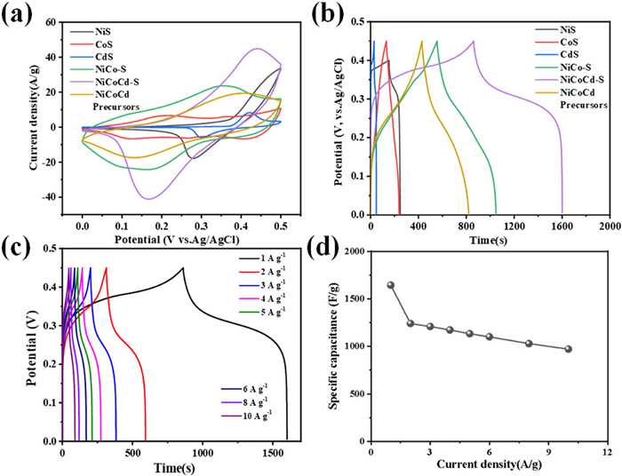
As shown in Fig. 3a, comparative cyclic voltammetry (CV) curves were obtained for NiS, CoS, CdS, NiCo-S, NiCoCd-Precursors, and NiCoCd-S at a scanning rate (ν) of 10 mV/s. Clear oxidation–reduction peaks are observed on the CV plots for different materials, indicating reversible Faradaic reactions during the electrochemical processes. Furthermore, the CV area of the NiCoCd-S electrode is significantly larger than that of NiS, CoS, CdS, NiCo-S electrodes, and NiCoCd-Precursors, indicating the enhanced capacitive electrochemical activity of NiCoCd-S material [31]. In contrast, CV curves for single-metal sulfides like NiS, CoS, and CdS exhibit the smallest integrated areas, further highlighting the synergistic effect of multi-metal sulfide electrode materials in improving electrode performance. The galvanostatic charge-discharge (GCD) profiles of different electrode materials are depicted in Fig. 3b. At CD of 1 A/g, NiCoCd-S exhibits the longest discharging time, indicating the highest capacitive performance, consistent with the CV test results.
Figure 3
Figure 3.
(a) The CV curves of different electrode materials at a scanning rate of 10 mV/s. (b) The GCD curves of different electrode materials at 1 A/g. (c) GCD curves of the NiCoCd-S electrode material at different current densities (CDs). (d) The specific capacity of the NiCoCd-S electrode material at different CDs.
To further investigate the energy storage characteristics of NiCoCd-S, GCD and cyclic stability tests were conducted. Fig. 3c shows the GCD curves for NiCoCd-S at different CDs. Analyzing the curves, it is evident that NiCoCd-S exhibits well-defined charge-discharge plateaus, characteristic of pseudocapacitive electrode behavior, in accordance with the results observed in the CV curves. Additionally, the GCD plot for NiCoCd-S displays excellent geometric symmetry, indicating good reversibility of the NiCoCd-S electrode material [32,33]. Based on the GCD results, the Cg of NiCoCd-S at different CDs is shown in Fig. 3d. At CDs of 1, 2, 3, 4, 5, 6, 8 and 10 A/g, the Cgs of the NiCoCd-S electrode material are 1643.7, 1240.4, 1208.6, 1172.4, 1133.3, 1100, 1029.3 and 971.1 F/g, respectively. NiCoCd-S electrode material retains 59.08% of its initial capacitance at 10 A/g, confirming its excellent rate capability, possibly attributed to the outstanding synergistic effect of the ternary metal sulfide [32,33]. To validate the cyclic stability performance of NiCoCd-S, 10,000 charge-discharge cycles were conducted at 10 A/g (Fig. S4 in Supporting information). The Coulombic efficiency of NiCoCd-S consistently remains around 99%, and the final capacity only experiences a loss of 18.4%.
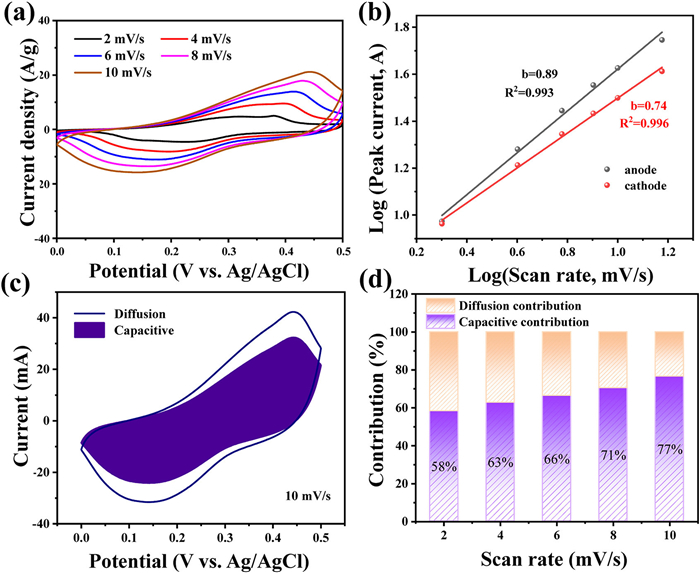
CV tests were performed on the NiCoCd-S nano-hollow-prism electrode material at a low scanning rate to delve into the energy storage mechanism and reaction kinetics of NiCoCd-S. The results are shown in Fig. 4a. The CV curve of NiCoCd-S at a low scan rate (2–10 mV/s, voltage range: 0–0.5 V) exhibits more distinct and complete oxidation–reduction peaks. Studying the relationship between peak current (i) and scanning rate (ν) allows for an investigation into the reaction kinetics. The relevant formula is as follows [34]:
i=aνb
(1)
logi=blogν+loga
(2)
Figure 4
Figure 4.
(a) CV curves of NiCoCd-S electrode at various scanning rates from 2 mV/s to 10 mV/s in a potential window of 0–0.5 V. (b) The relational graph between the logv and logi of NiCoCd-S electrode. (c) Capacitive and diffusion-controlled contributions of NiCoCd-S electrode for charge storage at ν of 10 mV/s. (d) The capacitive contribution from capacitive and diffusion contribution for NiCoCd-S electrode at different scanning rates.
In the formula, i represents peak current (A), ν is the scanning rate (mV/s), and a and b are adjustable parameters that can be calculated through fitting the logi vs. logν curve, as given in Eq. 2. When the value of b approaches 0.5, it indicates diffusion-controlled behavior, whereas when the value of b tends toward 1, it signifies surface capacitance control. The relationship between the anodic and cathodic i and ν obtained by fitting the logi vs. logν curve using Eq. 2 is presented in Fig. 4b, where the slope of the straight line represents the b value for the NiCoCd-S electrode material. The b values for the anodic and cathodic peaks are 0.89 and 0.74, respectively. These results suggest that charge storage in the NiCoCd-S electrode material is primarily limited by surface capacitive processes, but diffusion-controlled behavior also coexists.
In order to further investigate the energy storage mechanism of the NiCoCd-S electrode, the contributions from capacitance (h1ν) and diffusion control (h2ν1/2) were discussed. The specific formulas are as follows [35]:
i=h1ν+h2ν1/2
(3)
Fig. 4c depicts the capacitance and diffusion control contributions to charge storage in the NiCoCd-S electrode at a scanning rate of 10 mV/s. The capacitance contribution accounts for 77%, indicating the predominant capacitive-controlled behavior. The percentage contributions of surface control and diffusion control calculated for NiCoCd-S electrode material at different scanning rates in the range of 2–10 mV/s are shown in Fig. 4d. As the scan rate rises, the capacitance control contribution percentage gradually rises from 58% to 77%. Clearly, at lower scanning rates, both diffusion-controlled and capacitance-controlled processes jointly influence charge storage in the NiCoCd-S electrode material. However, at higher scanning rates, NiCoCd-S electrode material primarily exhibits dominant electrochemical behavior governed by surface capacitance control. These results suggest that NiCoCd-S, with its enhanced ion diffusion capability, exhibits a higher contribution from surface capacitance, making it an ideal pseudocapacitive material.
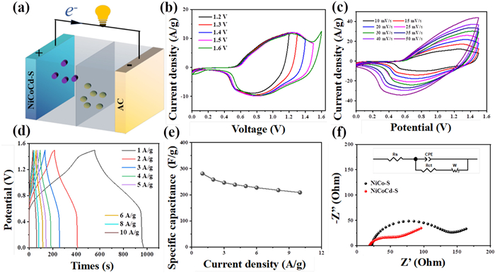
A hybrid supercapacitor device was fabricated using NiCoCd-S and activated carbon (AC) as the positive and negative electrodes, respectively. Fig. 5a illustrates the schematic diagram of the NiCoCd-S//AC hybrid supercapacitor structure. Fig. 5b shows the different voltage windows for the NiCoCd-S//AC device, and it can be observed that a slight polarization phenomenon occurs in the CV curve at a voltage window of 1.60 V. Clearly, the optimal voltage window for the NiCoCd-S//AC device should be 0–1.5 V. CV curves at different scanning rates of 10–50 mV/s for the NiCoCd-S//AC device with the voltage ranging from 0 to 1.5 V were studied, and the consequences are presented in Fig. 5c. It is worth noting that even when the ν rose to 50 mV/s, the profile of the CV curve does not transform significantly, indicating that NiCoCd-S//AC exhibits splendid rate performance. Fig. 5d displays the GCD curves at different CDs with working voltage ranging from 0 to 1.5 V. Furthermore, based on the corresponding GCD results, the Cg of the NiCoCd-S//AC device was calculated, and the consequences are presented in Fig. 5e. Specifically, at CDs of 1, 2, 3, 4, 5, 6, 8 and 10 A/g, the Cg of the NiCoCd-S//AC device are 276.5, 259.9, 246, 240.3, 232.3, 225.6, 213.9 and 201.3 F/g, respectively.
Figure 5
Figure 5.
(a) Schematic diagram of the NiCoCd-S//AC hybrid supercapacitors. (b) CV curves of the NiCoCd-S//AC device collected in different scanning voltage windows. (c) CV curves of the NiCoCd-S//AC device at different scanning rates with the voltage ranging from 0 to 1.5 V. (d) GCD curves of the HSC device at different CDs with the voltage ranging from 0 to 1.5 V. (e) The specific capacity of the NiCoCd-S//AC device at CDs of 1–10 A/g. (f) Nyquist plots of different electrode materials.
Impedance is one of the characteristics of materials, and Fig. 5f displays the consequences of the electrochemical impedance spectroscopy (EIS) fitting analysis for the materials. The semicircular arc in the high-frequency region and the straight line in the low-frequency region indicate the charge transfer resistance (Rct) of the electrode material and the diffusion resistance of the electrolyte, respectively. The equivalent circuit obtained from fitting the EIS curve is shown in the illustration of Fig. 5f [36]. The Rct for the NiCo-S electrode is 100.2 Ω, while the Rct for the NiCoCd-S electrode is 29.51 Ω. Clearly, NiCoCd-S exhibits lower electrochemical reaction resistance than NiCo-S, indicating that the addition of Cd enhances the electrical conductivity and ion diffusion rate of the electrode material.
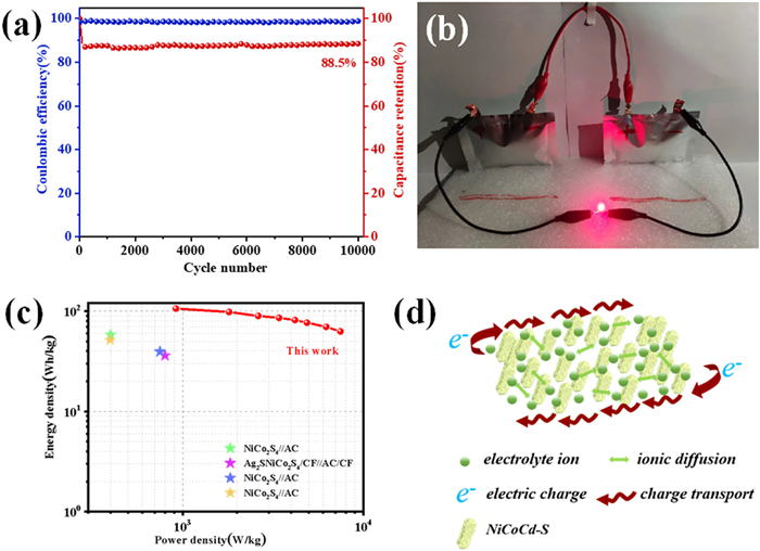
Based on the GCD curves at 10 A/g, a 10,000-cycle stability test was conducted to assess the stability performance of the prepared NiCoCd-S//AC hybrid supercapacitor, and the results are presented in Fig. 6a. After 10,000 charge-discharge cycles, the capacity retention of the hybrid supercapacitor remains as high as 88.5%, displaying that the NiCoCd-S//AC device can maintain excellent reversibility. To validate the practical application value of the NiCoCd-S//AC device, as shown in Fig. 6b, two NiCoCd-S//AC devices connected in series successfully illuminate a red LED after being charged, demonstrating the significant practical application potential of the NiCoCd-S//AC supercapacitor. Fig. 6c displays Ragone plots based on E and P. The maximum E of the NiCoCd-S//AC hybrid supercapacitor is 105.89 Wh/kg at a P of 919.22 W/kg, and at a high P of 7473.61 W/kg, its E remains as high as 62.7 Wh/kg. Furthermore, in comparison to other similar supercapacitors reported in the literature, the NiCoCd-S//AC hybrid supercapacitor demonstrates significant advantages in energy storage performance. For example, when compared toNiCo2S4//AC [37], AgS-NiCo2S4/CF//AC/CF [38], NiCo2S4//AC [39], and NiCo2S4//AC [40], the detailed parameter comparisons are displayed in Table S1 (Supporting information). As indicated in Fig. 6d, a possible electrochemical process mechanism for NiCoCd-S is proposed. A large number of electrolyte ions (green spheres) rapidly diffuse to the redox-active centers, participating in the pseudocapacitive reactions within the NiCoCd-S nano-hollow-prism material (yellow rhombi). Furthermore, thanks to its hollow structure, they can also migrate from the outer surface to the interior of NiCoCd-S. Simultaneously, the low resistance of NiCoCd-S nano-hollow-prism material provides the electrode with high conductivity, facilitating charge transfer (red arrows) and resulting in rapid response times during charge/discharge processes.
Figure 6
Figure 6.
(a) Cycle performance of the NiCoCd-S//AC device at 10 A/g. (b) The photograph of LED being lit up. (c) Ragone plots of the NiCoCd-S//AC device as compared with some previous devices. (d) Schematic diagram of charge transfer and ion diffusion in NiCoCd-S.
In conclusion, a three-dimensional nickel-cobalt-cadmium ternary metal sulfide hollow nanoprism material was successfully synthesized by combining refluxing, hydrothermal and calcination methods. The microstructure of NiCoCd-S and its electrochemical energy storage performance were comprehensively analyzed through characterization techniques such as SEM, TEM, XPS, as well as electrochemical tests like CV and GCD. Comparisons with electrode materials like NiS, CoS, CdS and NiCo-S revealed that the introduction of cadmium significantly improves the electrochemical properties of the electrode material. NiCoCd-S exhibits a high Cg of 1643.7 F/g at 1 A/g, with a remarkable capacitance retention of 81.6% after 10,000 cycles. The NiCoCd-S//AC asymmetric supercapacitor, with NiCoCd-S as the positive electrode and AC as the negative electrode, delivers an ultra-high E of 105.9 Wh/kg at a P of 919.2 W/kg. Even at a high P of 7473.6 W/kg, it maintains an E of 62.7 Wh/kg. Moreover, the NiCoCd-S//AC asymmetric supercapacitor exhibits excellent cyclic stability, retaining 88.5% of its initial capacitance after 10,000 charge-discharge cycles. These consequences certify that the three-dimensional nickel-cobalt-cadmium ternary metal sulfide hollow nanoprism material has excellent energy storage and stability performance, making it a highly promising electrode material for supercapacitors.
Declaration of competing interest
The authors declare that they have no known competing financial interests or personal relationships that could have appeared to influence the work reported in this paper.
The author thanks to the National Natural Science Foundation of China (Nos. 52362012, 42077162), Major Discipline Academic and Technical Leaders Training Program of Jiangxi Province (Nos. 20232BCJ22048, 20232BCJ22008), Natural Science Foundation of Jiangxi Province (No. 2022ACB203014), Educational Reform Project of Jiangxi Province (Nos. JXYJG-2022–135, JXYJG-2023–124), Key Laboratory of Jiangxi Province for Persistent Pollutants Prevention Control and Resource Reuse (No. 2023SSY02061), the Science and Technology Commission of Shanghai Municipality (No. 2024ZDSYS02), Nanchang Hangkong University Project (No. JY22017).
Supplementary materials
Supplementary material associated with this article can be found, in the online version, at doi:10.1016/j.cclet.2025.110954.
[1]
X.X. Zhang, G.M. Qu, Z.H. Wang, et al., Chin. Chem. Lett. 32 (2021) 2453–2458. doi: 10.1016/j.cclet.2021.01.042
Y.X. Chen, W. Zhong, F. Chen, et al., J. Mater. Sci. Technol. 121 (2022) 19–27. doi: 10.1016/j.jmst.2021.12.051
[31]
K. Amin, K. Krois, F. Muench, et al., J. Mater. Chem. A 10 (2022) 12473–12488. doi: 10.1039/d2ta00235c
[32]
W.Y. Yang, J. Wang, S. Gao, et al., J. Adv. Ceram. 11 (2022) 1735–1750. doi: 10.1007/s40145-022-0644-9
[33]
K. Lu, D. Li, X. Gao, et al., J. Mater. Chem. A 3 (2015) 16013–16019. doi: 10.1039/C5TA04244E
[34]
Z.Q. Liu, Y.L. Qiu, A.T. Zhang, et al., J. Mater. Chem. A 9 (2021) 22573–22584. doi: 10.1039/d1ta06706k
[35]
F.L. Lai, L.Z. Zuo, H.Y. Lu, et al., Small 12 (2016) 3235–3244. doi: 10.1002/smll.201600412
[36]
J.G. Dai, X.Q. Qi, L. Xia, et al., Adv. Funct. Mater. 33 (2023) 2212440. doi: 10.1002/adfm.202212440
[37]
S.M. Yang, W.H. Xiong, Z.K. Wu, et al., J. Energy Storage 44 (2021) 103407. doi: 10.1016/j.est.2021.103407
[38]
X.K. Wang, G.M. Qu, S.H. Hao, et al., J. Colloid Interf. Sci. 602 (2021) 712–720. doi: 10.1016/j.jcis.2021.06.063
[39]
Z.Q. Shi, X.T. Shen, Z. Zhang, et al., J. Colloid Interf. Sci. 604 (2021) 292–300. doi: 10.1016/j.jcis.2021.06.144
[40]
X. Ma, Q. Guo, J.M. Zhang, et al., Chem. Engin. J. 437 (2022) 135337. doi: 10.1016/j.cej.2022.135337
Figure 1
(a) Schematic illustration for the preparation process of NiCoCd-S hollow nanoprisms. SEM images of (b) NiCo precursor, (c) NiCoCd precursor, (d, e) NiCo-S and (f) NiCoCd-S. (g) TEM images, (h) HRTEM images, (i) selected area electron diffraction (SAED), (j-n) the elemental mappings of NiCoCd-S.
Figure 3
(a) The CV curves of different electrode materials at a scanning rate of 10 mV/s. (b) The GCD curves of different electrode materials at 1 A/g. (c) GCD curves of the NiCoCd-S electrode material at different current densities (CDs). (d) The specific capacity of the NiCoCd-S electrode material at different CDs.
Figure 4
(a) CV curves of NiCoCd-S electrode at various scanning rates from 2 mV/s to 10 mV/s in a potential window of 0–0.5 V. (b) The relational graph between the logv and logi of NiCoCd-S electrode. (c) Capacitive and diffusion-controlled contributions of NiCoCd-S electrode for charge storage at ν of 10 mV/s. (d) The capacitive contribution from capacitive and diffusion contribution for NiCoCd-S electrode at different scanning rates.
Figure 5
(a) Schematic diagram of the NiCoCd-S//AC hybrid supercapacitors. (b) CV curves of the NiCoCd-S//AC device collected in different scanning voltage windows. (c) CV curves of the NiCoCd-S//AC device at different scanning rates with the voltage ranging from 0 to 1.5 V. (d) GCD curves of the HSC device at different CDs with the voltage ranging from 0 to 1.5 V. (e) The specific capacity of the NiCoCd-S//AC device at CDs of 1–10 A/g. (f) Nyquist plots of different electrode materials.
Figure 6
(a) Cycle performance of the NiCoCd-S//AC device at 10 A/g. (b) The photograph of LED being lit up. (c) Ragone plots of the NiCoCd-S//AC device as compared with some previous devices. (d) Schematic diagram of charge transfer and ion diffusion in NiCoCd-S.

 DownLoad:

 下载:
下载:


 下载:
下载:
