Citation:
Jiaxuan Liu, Nan Zhang, Huiming Shi, Zhipeng He, Zhiyu Zhang, Dianlong Wang, Huakun Liu, Shixue Dou, Bo Wang. Single crystal P2-type layered cathodes with optimized crystal plane orientation improved high voltage stability for sodium-ion batteries[J]. Chinese Chemical Letters,
2026, 37(5): 110892.
doi:
10.1016/j.cclet.2025.110892
Single crystal P2-type layered cathodes with optimized crystal plane orientation improved high voltage stability for sodium-ion batteries
English
Single crystal P2-type layered cathodes with optimized crystal plane orientation improved high voltage stability for sodium-ion batteries
State Key Laboratory of Space Power-Sources, School of Chemistry and Chemical Engineering, Harbin Institute of Technology, Harbin 150001, China
b.
MIIT Key Laboratory of Critical Materials Technology for New Energy Conversion and Storage, School of Chemistry and Chemical Engineering, Harbin Institute of Technology, Harbin 150001, China
c.
Institute of Energy Material Science, University of Shanghai for Science and Technology, Shanghai 200093, China
d.
Institute for Superconducting & Electronic Materials, Australian Institute of Innovative Materials, University of Wollongong, Wollongong, NSW 2500, Australia
* Corresponding author at: State Key Laboratory of Space Power-Sources
Received Date:
09 December 2024 Accepted Date:
20 January 2025 Revised Date:
16 January 2025 Available Online:
15 May 2026
Abstract:
Traditional polycrystalline P2 layered oxides face challenges such as irreversible phase transitions, poor air stability, and structural distortion, which negatively impact their electrochemical performance. In this study, a single-crystal material, P2-Na2/3Ni1/4Mn2/3Mg1/12O2 (SC-NMM), was synthesized using co-precipitation coupled with the molten salt method. Owing to the strong integrity and high thermal stability of the main {001} planes of the large-sized single crystal, SC-NMM exhibits a high reversible specific capacity (173.5 mAh/g at 20 mA/g) and stable cycle performance (93.38% capacity retention after 100 cycles at 100 mA/g) at high voltage. Additionally, the Na-ion full cell constructed with the SC-NMM cathode and hard carbon anode demonstrates a cathode energy density of 397.4 Wh/kg. The excellent electrochemical performance of SC-NMM originates from the reversible anion redox and single-phase solid solution reaction mechanism. This work provides a reference for synthesizing single-crystal layered transition metal oxides with high electrochemical performance by eliminating irreversible phase transitions through crystal orientation modulation.
In recent years, the widespread application of portable electronic devices has driven the rapid development of lithium-ion batteries (LIBs). Due to their high discharge voltage, long cycle life, and environmental friendliness, LIBs have dominated the field of secondary batteries [1,2]. However, the scarcity and uneven distribution of lithium resources in the Earth's crust have limited the application of LIBs in large-scale energy storage systems [3]. Since the structure and reaction mechanism of sodium-ion batteries (SIBs) are highly similar to those of LIBs, SIBs have emerged as an alternative [4]. Compared to LIBs, SIBs offer advantages such as lower cost, good safety, and high ionic conductivity [5,6], making them more promising for use in next-generation large-scale energy storage systems [7,8]. Current research on SIBs is focused on the modification of cathode materials [9,10]. Layered transition metal oxides (LTMOs) are considered the most commercially viable cathode materials for SIBs due to their wide range, simple synthesis, high discharge voltage, and specific capacity [11,12]. These materials can be classified into O-type and P-type oxides based on the Na ions filling sites [13,14]. Compared to O-type oxides, P-type oxides have wider Na ions transport channels and better rate performance [15,16]. However, irreversible phase transition caused by interlayer slippage at high voltage remains a common issue for LTMOs in SIBs [17,18]. Phase transition not only results in significant voltage hysteresis [19,20] but also leads to substantial lattice distortion and approximately 0-20% contraction or expansion of the crystal axis [21], significantly affecting the electrochemical performance of the materials.
Another significant issue is that the LTMOs commonly prepared by solid-state synthesis consist of polycrystalline particles composed of numerous randomly oriented primary particles [22]. The grain boundaries formed by grains with different orientations significantly increase the transmission distance of Na ions and slow down the diffusion rate of Na ions [23]. The polycrystalline nature leads to anisotropy, which can cause mutual pushing or separation of particles, generating microcracks within the crystal when stress is applied. This allows electrolyte infiltration and the formation of new cathode electrolyte interphase (CEI) films, resulting in increased impedance [24,25]. In contrast, single crystals consist of primary particles with complete crystal shapes and sizes larger than 1 µm, without obvious grain boundaries, providing sufficient structural resistance to stress [26,27]. Furthermore, the separation between larger primary particles avoids the generation of microcracks [28]. Meanwhile, the smaller specific surface area reduces side reactions and parasitic phases between the surface and the electrolyte, resulting in better high-voltage stability and cycling stability compared to polycrystalline materials [29,30]. Shi et al. [31] synthesized single-crystal P3-Na0.75Mg0.08Co0.10Ni0.2Mn0.60O2 using the acetate-citrate method and demonstrated that doping with Mg ions effectively suppressed the P3-O3 phase transition. However, the preparation process is cumbersome, and it is difficult to control the single-crystal morphology, leaving large room for improvement. The co-precipitation process is simple and allows for easy control of elemental content, making it suitable for large-scale preparation of ternary LTMOs [32,33]. Additionally, the molten salt method provides a liquid environment during calcination by adding one or more types of molten salts, promoting particle growth and enabling the controlled formation of single crystals under specific reaction conditions [34,35].
Herein, we employed a combined co-precipitation and molten salt method to synthesize single-crystal P2-Na2/3Ni1/4Mn2/3Mg1/12O2 (SC-NMM) with uniform elemental distribution and a high proportion of {001} planes. This material exhibits a hexagonal plate-like structure with a radius of 1–2 µm. Compared to irregularly shaped, smaller radius polycrystalline materials (P-NMM), SC-NMM displays higher initial capacity, enhanced cycling stability, and superior rate capability due to its reversible anion redox, solid solution reaction mechanism and good Na ions transport kinetics. The overall integrity of the single crystal and the dominance of stable {001} planes endow SC-NMM with a robust structure, effectively suppressing irreversible phase transitions even at high cutoff voltages.
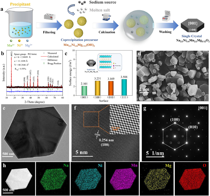
The synthesis route of SC-NMM is shown in Fig. 1a. First, Ni1/4Mn2/3Mg1/12(OH)2 precursor with a large radius was prepared by controlling reaction temperature, reaction time, and other factors. Due to the slow diffusion of ions, it is difficult to control the grain morphology thermodynamically in the solid-state method. Conversely, in the highly polarized liquid molten salt, the precursor can be evenly dispersed and dissociated, moving rapidly through convection and diffusion, resulting in a high migration rate and contact area [36]. Additionally, in the liquid molten salt, the crystal particles undergo Ostwald ripening, continuously dissolving and recrystallizing, and eventually grow into an energy-dominated hexagonal plate structure along the {001} planes. Because the {001} planes are parallel to the Na ions transport channel and serve as electrochemical inert planes, the SC-NMM with a high proportion of {001} planes exhibit high thermodynamic stability [37].
Figure 1
Figure 1.
(a) Illustration of single-crystal P2-Na2/3Ni1/4Mn2/3Mg1/12O2 material synthesis. (b) XRD Rietveld refinement with corresponding cell parameters. (c) Calculated surface energy of the different crystal planes. (d) SEM image. (e, f) HRTEM images. (g) SAED pattern. (h) EDX elemental mappings.
Fig. 1b and Fig. S1a (Supporting information) show the XRD patterns of SC-NMM, P-NMM and the pattern of SC-NMM refined by Rietveld, respectively. All the peaks in the XRD spectra show that the space group is P63/mmc hexagonal P2 phase. The peak intensity of SC-NMM corresponding to {001} planes at about 15° is much higher than that of other peaks, and its (001)/(100) peak intensity ratio is further improved compared with P-NMM, indicating that the liquid state environment provided by Na2MoO4 molten salt promotes the {001} planes oriented growth of single-crystal [38]. And the rietveld refinement of XRD data was employed to further investigate the structural characteristics of SC-NMM (Fig. 1b) and P-NMM (Fig. S1b in Supporting information), with refined parameters in Table S1 (Supporting information). Generally speaking, the parameters of SC-NMM and P-NMM are relatively close, indicating that the single-crystal preparation and crystal plane modulation will not change the crystal cell structure. Furthermore, the surface energy of crystal planes of P2-Na2/3Ni1/4Mn2/3Mg1/12O2 crystal was calculated by the first-principles calculations using density functional theory (DFT) (Fig. 1c). The surface energy of {001} planes is 2.101 J/m2, which is significantly lower (above 1 J/m2) than that of other crystal planes, indicating that {001} planes are the energy dominant planes of SC-NMM (Table S3 in Supporting information). It is consistent with the results of XRD spectrum.
The SEM images of SC-NMM and P-NMM are presented in Fig. 1d and Fig. S2a (Supporting information). P-NMM shows small particle size and irregular shape, with obvious agglomeration. SC-NMM exhibits a hexagonal plate-like structure with a radius of 1–2 µm and a smooth surface free of impurities, indicating a high proportion of {001} planes and typical single-crystal characteristics. Furthermore, the structure of SC-NMM was analyzed in detail using high-resolution transmission electron microscopy (HRTEM). A clearer hexagonal structure is observed in the Fig. 1e. The long-range ordered lattice stripes are displayed, and the lattice spacing is 0.254 nm, corresponding to the (100) crystal planes, proving the directional growth of the {001} planes in hexagonal prism particles (Fig. 1f). The selected area electron diffraction (SAED) image along the [001] zone axis (Fig. 1g) shows a distinct two-dimensional spot matrix rather than diffraction rings, further confirming the hexagonal single-crystal structure of SC-NMM [39]. The small spots are assigned to the TM honeycomb-ordered superstructure, which may be due to the high ratio (001) surface of SC-NMM promoting the ordered distribution of Ni, Mg and Mn ions, indicating that it can effectively stabilize the interlayer structure and strengthen the stability of SC-NMM [40]. The energy dispersive X-ray spectrometry (EDX) mapping images show that the elemental distributions in SC-NMM and P-NMM are consistent with the SEM images (Fig. 1h and Fig. S2d in Supporting information).
The chemical composition of SC-NMM and P-NMM was analyzed using inductively coupled plasma-optical emission spectrometry (ICP-OES), and the results show little difference from the design values, indicating the successful synthesis of P2-Na2/3Ni1/4Mn2/3Mg1/12O2 material (Table S4 in Supporting information). The valence states of transition metal elements in SC-NMM and P-NMM were analyzed using X-ray photoelectron spectroscopy (XPS) (Figs. S3a–d in Supporting information). The results show that the Ni 2p1/2 and 2p3/2 peaks of SC-NMM are located at 872.0 eV and 854.1 eV, respectively, corresponding to the +2-valence state (Fig. S3b). The two main peaks of Mn can be divided into four peaks. The peaks at 653.8 eV and 643.4 eV correspond to Mn4+, and the peaks at 653.2 eV and 641.5 eV correspond to Mn3+ (Fig. S3c). Compared to the corresponding images of P-NMM (Figs. S3e and f in Supporting information), the Mn4+ ions account for a higher proportion in SC-NMM, this may be attributed to the 3d orbital degeneracy of Mn promoted by the honeycomb-ordered superstructure. Due to the Jahn-Teller effect of Mn3+, which can easily lead to lattice distortion, SC-NMM with lower Mn3+ content will have better structural stability [41].
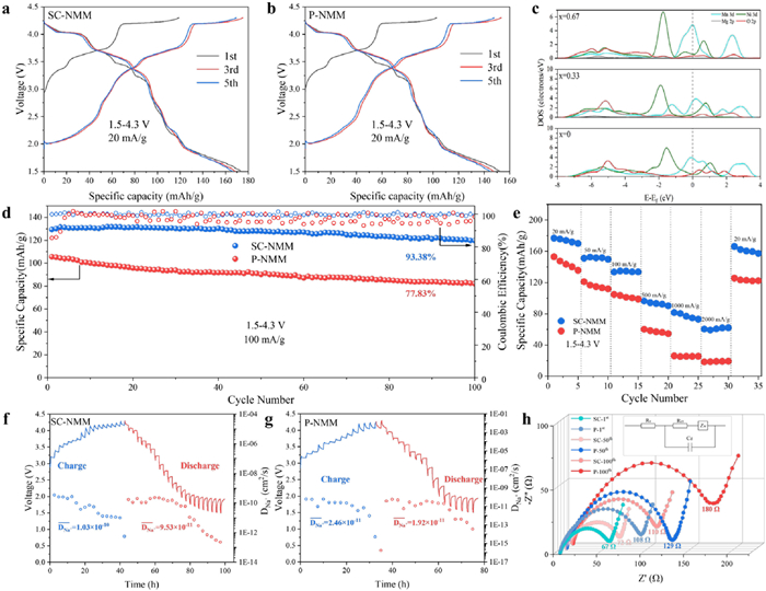
The electrochemical performance of SC-NMM and P-NMM in the Na half-cell was investigated in the voltage range of 1.5–4.3 V. Figs. 2a and b show the galvanostatic charge-discharge curves (GCD curves) of SC-NMM and P-NMM at 20 mA/g, respectively. The initial discharge capacity of SC-NMM is as high as 173.5 mAh/g, while that of P-NMM is only 152.4 mAh/g. The additional capacity of NMM is derived from the excitation effect of doped Mg ion on anion oxidation, and the difference is attributed to the flat Na ions channel and firm structure of SC-NMM, which can promote more Na ions intercalation/deintercalation. Fig. S4 (Supporting information) shows the CV curves of SC-NMM and P-NMM. The redox peaks of around 2.2/2.3 V correspond to Mn3+/Mn4+ couple, while the redox peaks of about 3.3/3.4 V and 3.6/3.75 V correspond to Ni2+/Ni3+ and Ni3+/Ni4+ couples, respectively, redox peaks above 4.0 V come from anionic oxidation reaction. The PDOS curves of NMM at different Na contents (0.67, 0.5, 0) are shown in Fig. 2c. It is proved that Mn, Ni ion and anion are involved in the capacity contribution [42], and the narrow band gap indicates that NMM has good conductivity. The calculated results are in good agreement with the CV results.
Figure 2
Figure 2.
Electrochemical performance of SC-NMM and P-NMM. GCD curves of (a) SC-NMM and (b) P-NMM at 20 mAh/g. (c) PDOS of P2-NaxNi1/4Mn2/3Mg1/12O2 (x = 0.67, 0.33 and 0). (d) Cycling performance of SC-NMM and P-NMM at 100 mAh/g. (e) Rate properties of SC-NMM and P-NMM. GITT curves of (f) SC-NMM and (g) P-NMM. (h) EIS spectra of SC-NMM and P-NMM in the first, 50th and 100th cycles.
The cycle performance of SC-NMM and P-NMM was tested at a current density of 100 mA/g. As shown in Fig. 2d and Fig. S6 (Supporting information), the initial discharge capacity of SC-NMM is 129.40 mAh/g, and the capacity after 100 cycles is 120.84 mAh/g, with a capacity retention rate of 93.38% and a coulombic efficiency stabilized at over 99%. Even under 300 cycles of long cycles, SC-NMM can still maintain 84.7% of its capacity, most of the capacity provided by anionic redox is retained, which indicates that SC-NMM has good cycle stability and reversibility of anionic redox. This stability is due to the combined stabilizing effect of large single crystals and high proportions of {001} planes in the lattice structures. The initial capacity of P-NMM is 105.66 mAh/g, and it exhibits significant capacity attenuation in the early stages of cycling, with a corresponding capacity retention rate of only 77.83% after 100 cycles and fluctuating coulombic efficiency. Fig. 2e shows the rate performance of SC-NMM and P-NMM at different current densities. SC-NMM can provide capacities of 176.8, 151.1, 133.5, 96.5, and 81.6 mAh/g at current densities of 20, 50, 100, 500, and 1000 mA/g, respectively. When the current density is further increased to 2000 mA/g, there is still a high capacity of 60.4 mAh/g, and when the current density returns to 20 mA/g, most of the capacity can be restored (166.3 mAh/g). In contrast, P-NMM only has a capacity of 18.5 mAh/g at a current density of 2000 mA/g, which is much lower than SC-NMM. This difference is due to the uniform and flat crystal facets and optimized crystal orientation of SC-NMM, which form fast transport channels for Na ions, resulting in good rate performance. However, Na ions in the bulk of P-NMM need to transport through complex grain boundaries to reach the surface, and the high Na-transfer resistance at the grain boundaries is detrimental to the diffusion of Na ions. Additionally, its large specific surface area increases the possibility of side reactions with the electrolyte at high current densities, further weakening its rate performance.
The kinetic characteristics of the intercalation/deintercalation process of Na ions were tested using galvanostatic intermittent titration technique (GITT) tests. The diffusion coefficient of Na ions (DNa+) is calculated using Fick's second law of diffusion. Figs. 2f and g show the GITT curves of SC-NMM and P-NMM. It can be observed that the DNa+ of SC-NMM is in the range of 10-9-10-12 cm2/s, proving its high ionic and electronic conductivity. The average DNa+ of P-NMM is about 5 times lower than that of SC-NMM, and it decreases significantly to 10-16 cm2/s at the end of charging. Its irreversible phase transition at high voltage leads to structural distortion, which severely hinders the transport of Na ions [43]. The kinetics of Na ions transport was analyzed using electrochemical impedance spectroscopy (EIS). The Nyquist results of SC-NMM and P-NMM under different cycle numbers are shown in Fig. 2h. All Nyquist plots consist of semicircles and slanted lines. As the cycle progresses, the charge transfer resistance Rct of P-NMM increases from 108 Ω to 180 Ω. In contrast, the initial Rct of SC-NMM is 67 Ω, and after cycling, it is only 110 Ω. Both the initial value and the growth rate are lower than those of P-NMM. Figs. S8a-d (Supporting information) show the 3D surface plots of the dQ/dV curves for 100 electrochemical cycles of SC-NMM and P-NMM. The higher the corresponding peak value, the warmer the color mapping, and the top diagram is the projection of the differential capacity curve. It is clear that the peaks of the differential capacitance curves correspond well with the redox peaks in the CV curves. In the low voltage region, the charge and discharge dQ/dV curves of SC-NMM have stronger peaks, indicating higher specific capacity and better Na ions intercalation kinetics. Additionally, after a long-term cycle, SC-NMM can maintain a stable peak value of differential capacity, while the peak value of P-NMM decays rapidly with the cycle [44]. In addition, the overcharge performance of SC-NMM and P-NMM were tested (Fig. S9 in Supporting information). Although the overcharge cycle stability of SC-NMM and P-NMM decreased, the stability advantage of single crystal is still very obvious compared with polycrystalline, indicating that the single crystal morphology reduces the side reactions between the material and electrolyte, and inhibits the structural degradation under high voltage. The low temperature performance of SC-NMM were additionally characterized (Fig. S10 in Supporting information). SC-NMM still has certain performance in low temperature environment, showing a wide range of application scenarios, and can better meet the needs of commercialization.
LTMOs with large interlayer spacing are more sensitive to air and are easy to react with water and carbon dioxide in the air [45]. In order to further verify the air stability of SC-NMM and P-NMM, after they were exposed to air for 30 days, XRD tests were carried out again and compared. Benefiting from the strong resistance of the {001} planes with high thermodynamic stability to air (Figs. S11a and b in Supporting information). P-NMM has a large peak intensity attenuation, while the characteristic peaks of SC-NMM are still obvious, and no hydration peak is observed. At the same time, these materials exposed to air for 7 days were assembled into a Na half-cell and the cycle performance was tested (Figs. S12a–c in Supporting information). The specific capacity of SC-NMM decreases only slightly (6.3 mAh/g), and still has a good capacity retention rate, while the cycling performance of P-NMM deteriorated significantly upon exposure to air (from 77.83% to 59.43%). These results demonstrate the excellent air stability of SC-NMM, thus the adverse effect of the formation of slurry gel on the battery performance can be avoided. And to explore the structural retention ability of the materials more intuitively, SEM images of the SC-NMM and P-NMM electrodes were collected after cycling (Figs. S13a and b in Supporting information). After multiple cycles under high current density and high cut-off voltage, it is clear from Fig. S13a that SC-NMM still maintains the integrity of the particles. No interlayer slips due to Na ions deintercalation, nor microcracks generated by lattice distortion and electrolyte erosion, are found. By comparison, Fig. S13b shows that P-NMM exhibits particle breakage after cycling. This breakage is due to the structural collapse caused by the anisotropy of polycrystalline materials. Conventional LTMOs have weak van der Waals interactions and are prone to dislocation [46], while the good integrity of single crystals prevents lattice fracture caused by internal stress, leading to improved mechanical strength.
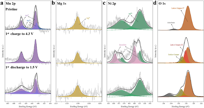
In order to explore the change of ionic valence state and anion activity of the material in the cycle process, ex-situ XPS tests were carried out on the electrodes of SC-NMM and P-NMM in the pristine, charged to 4.3 V and discharged to 1.5 V, respectively (Figs. 3a–d and Fig. S14 in Supporting information). The XPS images of SC-NMM and P-NMM plates in the pristine are similar to Fig. S3. During the cycle, the Mn ion of SC-NMM and P-NMM both provided part of the capacity and could well return to the initial state. The peak of Mg 1s at 1305 eV is attributed to Mg2+, indicating that Mg ion always remain electrochemically inert. When charging to 4.3 V, the newly appeared 857.5 eV and 875.1 eV peaks in the Ni 2p spectrum correspond to Ni3+ ion, indicating that Ni ion is the main capacity source. When discharging to 1.5 V, all Ni3+ ion in SC-NMM is reduced to Ni2+ ion, while there are still Ni3+ ion left in P-NMM. The peaks of 529.5, 530.5 and 531.5 eV in the O 1s spectra correspond to lattice oxygen O2-, peroxy ion O2n- and surface oxygen, respectively. Peroxy ion and surface oxygen were observed in SC-NMM and P-NMM at high voltage, which proved that Mg2+ effectively stimulated the activity of anion. However, after discharge to 1.5 V, more surface oxygen and peroxy ion can still be observed in P-NMM, while most peroxy ion in SC-NMM are reduced to lattice oxygen. Therefore, SC-NMM has highly reversible redox of transition metal ion and anion, which can provide additional charge compensation and inhibit the escape of oxygen, thus greatly enhancing the capacity and cycle stability.
Figure 3
Figure 3.Ex-situ XPS of SC-NMM at different charge/discharge states. (a) Mn 2p, (b) Mg 1s, (c) Ni 2p and (d) O 1s.
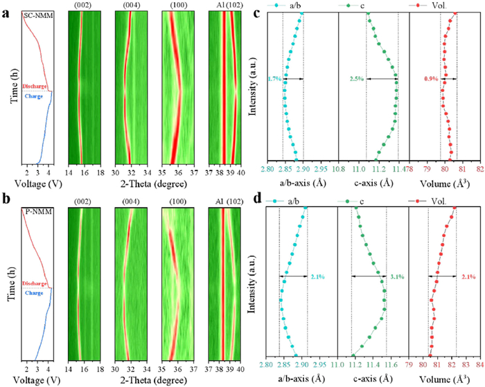
To investigate the crystal structure evolution of materials during the charge and discharge processes, in-situ XRD tests were performed on SC-NMM and P-NMM cathodes. Figs. S15a and b (Supporting information) show the in-situ waterfall plots of SC-NMM and P-NMM, respectively. The (002) and (004) peaks of both samples continuously shift towards lower angles upon Na ions extraction, indicating an increase in the electrostatic repulsion between individual TMO2 layers, leading to an increase in the interlayer spacing and expansion of the c-axis. However, the (100) and (102) peaks shift towards higher angles, corresponding to a decrease in the a/b axis caused by the oxidation of transition metal ions. Figs. 4a and b show the in-situ XRD contour maps of SC-NMM and P-NMM, respectively. When charged to high voltage (approximately 4 V), multiple interruptions can be observed in the contour map of P-NMM, indicating a "P2-O2" phase transition. SC-NMM maintains good consistency throughout the cycle process, demonstrating that it is dominated by a solid solution reaction mechanism and maintains a P phase structure [47]. The large size and high proportion of thermodynamically stable {001} planes in single crystals greatly increase the integrity of TMO2 layers while providing more Na ions sites to exert a "pinning" effect on the TMO2 layer, hindering its slip, thereby giving SC-NMM higher phase stability than conventional LTMOs [26]. The lattice parameter changes of SC-NMM and P-NMM were fitted and shown in Fig. 4c and d. The volume change of P-NMM can reach up to 2.1% (Fig. 4d), demonstrating relatively high volume variation during cycling. Conversely, SC-NMM's volume change by only 0.9% (Fig. 4c), showing its highly reversible structural changes and zero strain characteristics.
Figure 4
Figure 4.
Voltage profiles and contour plots of in-situ XRD patterns for (a) SC-NMM and (b) P-NMM. Cell parameter change of (c) SC-NMM and (d) P-NMM.
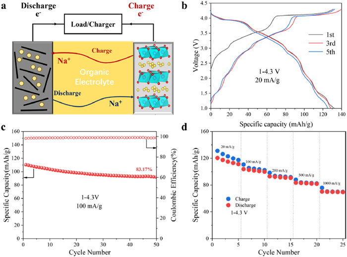
To further validate the applicability of SC-NMM material, a sodium-ion full cell was constructed by pairing it with a commercial hard carbon anode and tested within a voltage range of 1.0–4.3 V. Initially, the electrochemical performance of the hard carbon anode in the half-cell configuration was examined. As illustrated in Figs. S16a and b (Supporting information), the hard carbon anode can deliver a reversible capacity of 272 mAh/g at a current density of 20 mA/g. After 50 cycles at a current density of 100 mA/g, the capacity retention rate remains high at 92%, indicating excellent performance. Fig. 5a depicts the operational mechanism of the SIB. Fig. 5b indicates that the initial discharge capacity of the full cell at 20 mA/g is 132.2 mAh/g, with an average output voltage of approximately 3.01 V. Based on the mass of the cathode material, the calculated energy density is 397.4 Wh/kg. The capacity retention after 50 cycles at 100 mA/g is maintained at 83.2%, with a coulombic efficiency exceeding 98% (Fig. 5c), demonstrating good cycle stability. Furthermore, Fig. 5d shows that the system retains a capacity of 69.4 mAh/g even at a high current density of 1000 mA/g, underscoring its potential for commercial applications.
Figure 5
Figure 5.
Electrochemical performance of Na-ion full cell. (a) Schematics of Na-ion full cell. (b) GCD curves of full cell at 20 mAh/g. (c) Cycling performance of full cell at 100 mAh/g. (d) Corresponding capacities of full cell at different current densities.
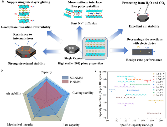
Based on the above discussion, Fig. 6a summarizes the excellent characteristics of SC-NMM in four aspects, including reversible phase transition, structural stability, air stability, and superior rate performance. The high proportion of {001} planes strengthen the interaction between TMO2 plates, thereby promoting reversible redox of anion. The integrity of large-sized single crystals suppresses the slip of TMO2 plates and maintains the solid solution reaction mechanism. the grain boundary-free characteristic allows it to avoid the generation of intergranular cracks. The small specific surface area of SC-NMM reduces its contact with air, while helping to reduce side reactions with electrolyte and form a good CEI film [48]. In addition, compared with P-NMM with massive grain boundaries, SC-NMM has a smoother Na ions diffusion channel, which is more conducive to the intercalation/deintercalation of Na ions. Consequently, SC-NMM exhibits significant advantages over the polycrystalline material P-NMM across various dimensions (Fig. 6b) and is ranked among the top in comprehensive performance among previously reported LTMOs cathode materials in existing research (Fig. 6c, additional information can be found in Table S5 in Supporting information).
Figure 6
Figure 6.
(a) Schematic diagram of the mechanism of the excellent performance of SC-NMM. (b) Performance comparison of SC-NMM and P-NMM cathode materials. (c) Comparison of specific capacity and capacity retention in different LTMOs cathode materials.
In summary, SC-NMM with high {001} planes was prepared using co-precipitation and molten salt methods. Compared to polycrystalline materials, SC-NMM exhibits significantly superior performance at high voltage. Its initial discharge specific capacity at 20 mA/g is 173.5 mAh/g and the capacity retention rate after 100 cycles at 100 mA/g is 93.38%. DFT calculations indicate that the hexagonal flake structure of SC-NMM stems from the low surface energy of the {001} planes, resulting in high thermodynamic stability. Ex-situ XPS spectra show that SC-NMM has good reversibility of anion redox. In-situ XRD results demonstrate that SC-NMM maintains the P phase throughout the cycling process, exhibiting a solid solution reaction mechanism. The integrity of large single crystals in SC-NMM suppresses irreversible phase transitions caused by interlayer slip and resists structural distortions from lattice internal stress. Furthermore, the highly stable {001} planes effectively resist erosion by water molecules and electrolytes, forming fast transport channels for Na ions. This study establishes the application advantages of single-crystal LTMOs in cathode materials for SIBs and provides a theoretical basis for designing crystalline materials with excellent performance through crystal orientation modulation.
Declaration of competing interest
The authors declare that they have no known competing financial interests or personal relationships that could have appeared to influence the work reported in this paper.
P.F. Wang, Y. You, Y.X. Yin, et al., Adv. Energy Mater. 8 (2017) 1701912.
[46]
Y. Sun, S. Guo, H. Zhou, Energy Environ. Sci. 12 (2019) 825–840. doi: 10.1039/C8EE01006D
[47]
L. Yao, P. Zou, C. Wang, et al., Adv. Energy Mater. 12 (2022) 2201989. doi: 10.1002/aenm.202201989
[48]
N. Zhang, B. Wang, F. Jin, et al., Cell Report. Phys. Sci. 3 (2022) 101197. doi: 10.1016/j.xcrp.2022.101197
Figure 1
(a) Illustration of single-crystal P2-Na2/3Ni1/4Mn2/3Mg1/12O2 material synthesis. (b) XRD Rietveld refinement with corresponding cell parameters. (c) Calculated surface energy of the different crystal planes. (d) SEM image. (e, f) HRTEM images. (g) SAED pattern. (h) EDX elemental mappings.
Figure 2
Electrochemical performance of SC-NMM and P-NMM. GCD curves of (a) SC-NMM and (b) P-NMM at 20 mAh/g. (c) PDOS of P2-NaxNi1/4Mn2/3Mg1/12O2 (x = 0.67, 0.33 and 0). (d) Cycling performance of SC-NMM and P-NMM at 100 mAh/g. (e) Rate properties of SC-NMM and P-NMM. GITT curves of (f) SC-NMM and (g) P-NMM. (h) EIS spectra of SC-NMM and P-NMM in the first, 50th and 100th cycles.
Figure 5
Electrochemical performance of Na-ion full cell. (a) Schematics of Na-ion full cell. (b) GCD curves of full cell at 20 mAh/g. (c) Cycling performance of full cell at 100 mAh/g. (d) Corresponding capacities of full cell at different current densities.
Figure 6
(a) Schematic diagram of the mechanism of the excellent performance of SC-NMM. (b) Performance comparison of SC-NMM and P-NMM cathode materials. (c) Comparison of specific capacity and capacity retention in different LTMOs cathode materials.

 DownLoad:

 下载:
下载:


 下载:
下载:
