Theoretical simulation and experimental study toward the isomerization of dibenzothiophene based hole transporting materials for perovskite solar cells
Citation:
Ruiqin Wang, Lei Yang, Jiayi Qi, Xin Chen, Ming Li, Yong Hua, Rongxing He, Xiaorui Liu. Theoretical simulation and experimental study toward the isomerization of dibenzothiophene based hole transporting materials for perovskite solar cells[J]. Chinese Chemical Letters,
2026, 37(5): 110891.
doi:
10.1016/j.cclet.2025.110891
Theoretical simulation and experimental study toward the isomerization of dibenzothiophene based hole transporting materials for perovskite solar cells
English
Theoretical simulation and experimental study toward the isomerization of dibenzothiophene based hole transporting materials for perovskite solar cells
Chongqing Key Laboratory of Soft-Matter Material Chemistry and Function Manufacturing, School of Chemistry and Chemical Engineering, Southwest University, Chongqing 400715, China
b.
Yunnan Key Laboratory for Micro/Nano Materials & Technology, School of Materials and Energy, Yunnan University, Kunming 650091, China
c.
State Key Laboratory of Mechanics and Control of Mechanical Structures, Key Laboratory for Intelligent Nano Materials and Devices of the Ministry of Education, Institute for Frontier Science, College of Mechanical and Electrical Engineering, Nanjing University of Aeronautics and Astronautics, Nanjing 210016, China
Received Date:
20 November 2024 Accepted Date:
20 January 2025 Revised Date:
15 January 2025 Available Online:
15 May 2026
Abstract:
Structural design is an effective way to realize the functional construction of hole transporting materials (HTMs). In order to have an insight into the relationship between molecular structure and function of HTMs, three isomeric HTMs (RQ1, RQ2 and RQ3) are constructed with functional group of dibenzothiophene which is connected to different positions on the side chains of carbazole-aromatic derivatives. In combination with computational simulation and experimental study, although the isomeric RQ1–RQ3 with the same molecular formula exhibit similar frontier molecular orbital energy levels and optical absorption, their hole transporting ability and interaction at perovskite/HTMs interface in perovskite solar cells (PSCs) are completely different. In comparison with the RQ2 (18.69%) and RQ3 (22.56%), the results indicate that the molecule RQ1 in PSCs application can yield higher power conversion efficiency (23.50%) because of its higher hole mobility and effective charge transfer at perovskite/HTMs interface. Moreover, the mutually corroborating between the computational simulation and the experimental results demonstrate the reliability of the theoretical model for molecular design of isomeric HTMs. This strategy of obtaining high-performance HTMs through simple structural design is expected to inspire researchers to further optimize the efficiency of PSCs.
Perovskite solar cells (PSCs) have experienced a groundbreaking increase in power conversion efficiency (PCE) over the past decades, thanks to advancements in device fabrication techniques and continuous optimization of constituent materials. Currently, PSCs with the highest certified PCE rely on organic small-molecule multifunctional hole transport materials (HTMs) [1]. Positioned between the electrode material and the perovskite layer, HTMs play a critical role in transporting and extracting photogenerated carriers as well as protecting the perovskite [2,3]. In recent years, researchers have demanded that advanced HTMs not only exhibit high hole mobility, energy level compatibility with adjacent layers, and acceptable costs but also effectively suppress defects at the perovskite surface and grain boundaries to inhibit charge recombination [4-6]. Inevitably, a large number of defects, including under-coordinated Pb2+ and I− vacancies, arise at the interface between the hole transport layer (HTL) and the perovskite layer. A common industry solution is to introduce a passivation layer between the HTL and the perovskite, which can increase production costs and complexity [7]. A prevalent strategy to endow HTMs with passivation capabilities is to incorporate functional groups containing atoms like S, F, and N [8,9]. However, this can lead to uncontrollable variations in their ability to extract and transport holes. Therefore, discovering new HTMs with enhanced hole separation/extraction capability, defect passivation ability, and other superior photovoltaic properties is crucial for advancing the commercial viability of PSCs.
To achieve efficient hole extraction, high mobility, suppression of interfacial charge recombination, and enhanced moisture resistance, the electron-donating thiophene group is often incorporated into HTM molecular structures [10-15]. The sulfur atom can enhance interactions between the molecule and perovskite, improving hole extraction by passivating surface defects. Additionally, the π-conjugated structure of thiophene tends to stack through strong π–π interactions, resulting in excellent hole mobility. Chen et al. [16] designed and synthesized four HTMs based on a dithienopyrrole (DTTP) core through a dual-strategy approach (conjugation engineering and side-chain engineering). DTTP-ThSO exhibited good planarity, high-quality film formation, matching energy levels, high hole mobility, and strong defect passivation capabilities due to its ester side chains forming a six-membered ring with thiophene via S···O non-covalent conformational locking. Specifically, undoped PSCs based on DTTP-ThSO achieved a fill factor (FF) of 82.3% and an impressive PCE of 23.3%. Ding et al. [17] reported a novel HTM with a three-dimensional conjugated structure named FTPE-ST. FTPE-ST features a twisted conjugated dibenzo(g, p) chrysene core and a planar 3,4-ethylenedioxythiophene (EDOT) as an extended electron-donating unit, forming a 3D configuration that provides multidirectional charge transport capability. Moreover, the sulfur atom in the EDOT unit can coordinate with Pb ions on the perovskite surface, enhancing interfacial interactions and suppressing interfacial defects. PSCs based on FTPE-ST achieved a maximum PCE of 25.21% and enhanced stability. Molecular units with extended π-conjugated planes can significantly modulate the hole mobility and conductivity of HTMs. Among them, dibenzothiophene (DBT) exhibits distinct advantages, primarily due to its effective defect passivation, which enhances device performance and stability. Chen et al. [18] identified a potential HTM (CQ2) with a conjugated π-bridge structure through theoretical calculations. The synthesized dopant-free CQ2, with DBT as the core, exhibited excellent photovoltaic performance in PSCs, attributed to its favorable surface morphology and high hole mobility. Similarly, Yang et al. [15] developed three D-π-D type HTMs featuring dibenzo-heterocycles core. Among them, DBT-based S-CBz showed strong interactions with PbI2, effectively passivating uncoordinated Pb2+ ions and reducing iodine vacancies. Specifically, PSCs based on S-CBz achieved FF of 83.7% and a remarkable PCE of 25%, along with excellent stability.
In molecular engineering, adjusting the isomers of HTMs is beneficial for exploring the relationship between molecular structure and performance. Liu et al. [19] designed four spiro derivative isomers by altering the substitution position of the terminal units. The study found that the substitution position of the terminal units significantly influenced the material properties, with spiro-4 exhibiting a low highest occupied molecular orbital (HOMO) level, high thermal stability, and good solubility, leading to a high PCE. Lu et al. [20] designed two isomers, XJ2 and XJ3, by altering the position of the carbonyl group on the pyridine ring. Their research revealed that the different positions of the carbonyl group affected the electronic properties of the molecules, particularly XJ2 with a meta-substitution, which exhibited a low HOMO energy level and high hole mobility, demonstrating stronger passivation effects due to a smaller steric hindrance.
In an increasing number of studies, theoretical methods such as density functional theory (DFT), time-dependent density functional theory (TD-DFT), Marcus theory, and molecular dynamics (MD) simulations have been employed to analyze and predict the geometric configurations, charge transport, and interfacial properties of HTMs molecules [21-24]. These methods provide a broad theoretical framework for guiding the design of HTM molecules. For instance, Xia et al. [25] discussed a series of novel butterfly-shaped HTMs. First-principles calculations and MD simulations indicated that foldable HTMs can transform discrete trap states in perovskites into continuous valence bands, thereby reducing trap-assisted recombination. By adjusting the foldability of HTMs, the wavefunction overlap between defect and perfect surface sites can be modulated, resulting in a PCE of 23.22% for small-area cells and 21.71% for large-area modules.
Considering the above, we designed suitable HTMs by altering the substitution positions of DBT on the side chains to investigate the structure-function relationship and charge transport properties of HTMs. Considering steric effects and the computational and synthesis cost, three more cost-effective isomers were selected to study the structure-function relationship and charge transport characteristics of HTMs based on heteroatom-containing side chains. As illustrated in Fig. 1a, the DBT group is attached to three different positions on the carbazole-based arylamine derivative side chain, designated as RQ1–RQ3. Various theoretical methods, including DFT, TD-DFT, MD, and Marcus theory, were employed to study the geometrical structures, frontier molecular orbital levels, optical absorption, and hole transport properties of RQ1–RQ3 molecules [26,27]. Additionally, first-principles and MD methods were utilized to explore the interfacial properties of RQ1–RQ3 at the perovskite interface, such as interfacial charge transfer characteristics between the perovskite and HTMs. The computational results provided deep insights into the properties and behaviors of these molecules at the perovskite interface: Due to the different substitution positions of DBT, RQ1–RQ3 exhibited distinct intermolecular and interfacial interaction patterns, leading to variations in charge transfer and covalent interactions, ultimately resulting in different hole transport capabilities and macroscopic adsorption structures on the perovskite. To validate the theoretical results, RQ1–RQ3 were synthesized and applied in PSCs. It was found that the substitution position of DBT significantly impacts PSC performance, with RQ1 demonstrating superior hole mobility, optimal film morphology, and the ability to suppress interfacial recombination as an HTM in PSCs. Consequently, under identical conditions, the PCE of PSCs based on RQ1 increased to 23.50%, compared to 18.69% and 22.56% for the other isomers, RQ2 and RQ3, respectively. The experimental results closely matched the theoretical simulations, demonstrating the reliability of our theoretical model. These findings highlight the importance of the substitution position of side chains in HTMs for the photovoltaic performance of PSCs and reveal the potential of molecular engineering in designing efficient HTMs.
Figure 1
Figure 1.
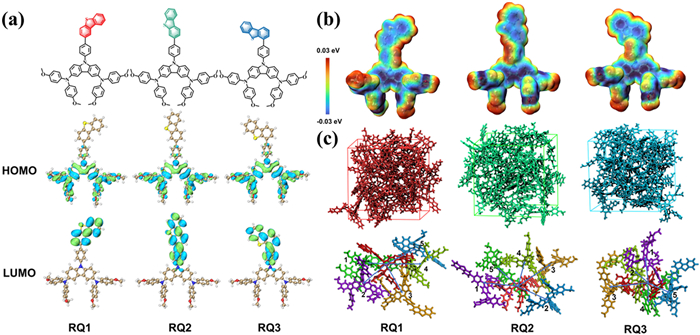
(a) Chemical structures and the schematic diagram of the frontier molecular orbitals for three isomeric molecules in this study. (b) Electrostatic surface potential (ESP) images of RQ1–RQ3. (c) After simulating for 10 ns using MD methods, the final morphologies of RQ1–RQ3 and main charge hopping pathways extracted.
Based on Fig. 1a, the DBT groups are attached to the 2nd, 3rd, and 4th positions of the terminal benzene ring, respectively named RQ1, RQ2, and RQ3. As shown in Fig. S1 (Supporting informaiton), the ground-state geometries of RQ1–RQ3 were optimized at the B3P86/6–311G(d, p) functional and basis set level. In Fig. 1b, the molecular electrostatic surfaces potential (ESP) of RQ1–RQ3 are evaluated, showing that the negative charges (blue regions) are primarily localized on the O atoms, carbazole plane, and DBT plane, while the positive charges (red regions) are mainly concentrated on the H atoms. The DBT groups in the side chains of all three molecules exhibit significant negative charge regions, indicating their Lewis basicity, which can aid in passivating interfacial defects caused by uncoordinated Pb ions [11].
The generation of photocurrent in PSCs relies on the alignment of energy levels between the HTM and the perovskite. We evaluated the HOMO and lowest unoccupied molecular orbital (LUMO) values of RQ1–RQ3. As shown in Table 1, the HOMO values of RQ1, RQ2, and RQ3 are −5.11, −5.11, and −5.10 eV, respectively, while the LUMO values are −2.43, −2.59, and −2.47 eV, respectively. These HTMs have HOMO/LUMO levels higher than the valence band (VB) and conduction band (CB) of the perovskite, ensuring that they effectively prevent electron injection, suppress interfacial charge recombination, and facilitate hole transport to the electrode [28]. As illustrated in Fig. 1a, RQ1–RQ3 exhibit similar HOMO orbital delocalization, with RQ1′s LUMO mainly distributed on the surface of the dibenzothiophene, while RQ2 and RQ3 show extended LUMO distributions. This difference could be attributed to the varying degrees of conjugation in the molecules caused by the different DBT substitution positions.
Table 1
Table 1.
Simulated HOMO (eV), LUMO (eV), Eg (eV), absolute hardness η (eV) and absorption wavelengths λabs (nm), emission wavelengths λem (nm), oscillator strength, assignments and Stokes shift (nm) of RQ1–RQ3.
Typically, the stability of organic molecules is evaluated using their absolute hardness (η), which represents the resistance of the chemical potential to changes in electron number. A higher η value indicates greater molecular stability [29]. As shown in Table 1, the η values of these HTMs are RQ1 (2.46 eV) > RQ3 (2.41 eV) > RQ2 (2.33 eV), suggesting that RQ1 exhibits better stability than RQ2 and RQ3. In dichloromethane (CH2Cl2) solvent, the UV-vis absorption spectra of RQ1–RQ3, calculated using the TD-PBE0/6–31G(d) functional and basis set, are depicted in Fig. S2 (Supporting information) with the corresponding optical data recorded in Table 1. The maximum absorption wavelengths (λmax, abs) and oscillator strengths (f) for RQ1–RQ3 are 402, 418, and 402 nm, and 0.04, 0.28, and 0.07, respectively. At these maximum absorption wavelengths, the primary electronic transitions for RQ1–RQ3 are HOMO → LUMO + 2, HOMO → LUMO, and HOMO → LUMO + 1, respectively. These molecules exhibit no significant absorption in the visible spectrum, which ensures they do not interfere with the light absorption by the perovskite. The calculated emission wavelengths and Stokes shifts for the three materials are 446, 529, 444 nm, and 44, 111, 42 nm, respectively. RQ2 has a larger emission wavelength and Stokes shift, likely due to a greater structural change between its excited and ground states [18].
The hole mobility (µh) is a crucial parameter characterizing the performance of HTMs, significantly influencing the efficiency of PSCs. First, we simulated the hole reorganization energy (λh) for RQ1–RQ3. As shown in Table 2, the λh values for RQ1, RQ2, and RQ3 are 0.397, 0.317, and 0.318 eV, respectively. Besides λh, the charge transfer rate (kij) is also affected by the charge transfer integral (vh), which is related to the stacking configuration and orbital overlap between adjacent HTM molecules [30]. Here, a unit of 24 molecules was subjected to MD simulation, and the primary hole transport pathways for RQ1–RQ3 were extracted from the final structures. Fig. 1c illustrates the morphology of RQ1–RQ3 after 10 ns of simulation, along with the identified hole transport pathways for each HTM. According to the computational results in Table 2, the simulated µh values for these HTMs are ranked as follows: RQ1 (2.21 × 10⁻² cm2 V−1 s−1) > RQ3 (5.09 × 10⁻³ cm2 V−1 s−1) > RQ2 (2.02 × 10⁻⁴ cm2 V−1 s−1). The µh of RQ1–RQ3 is primarily contributed by the pathways with the highest vh values, specifically RQ1 Pathways 3 (−2.07 × 10⁻² eV), RQ2 Pathways 1 (−1.28 × 10⁻³ eV), and RQ3 Pathways 2 (1.23 × 10⁻² eV).
Table 2
Table 2.
The reorganization energy λ (eV), charge transfer integral vh (eV), hole transport rate kij (s−1), center-of-mass distance ri (Å) and hole mobility uh (cm2 V−1 s−1) of main hopping pathway selected on basis of the MD simulations for RQ1–RQ3.
The value of vh depends on the extent of overlap between the molecular orbitals in the stacking model, as hole transfer primarily occurs in the regions where the HOMO orbitals overlap. As shown in Fig. 2a, the intermolecular interactions in these dimer fragments were visualized using the interaction region indicator (IRI) method [31]. The isosurfaces transitioning from blue to green to red represent bonding interactions, van der Waals interactions, and steric hindrance, respectively. The dimers in RQ1 Pathways 3 adopt a "tail-to-tail" stacking configuration, with interactions predominantly governed by van der Waals forces occurring near the diphenylamine-carbazole groups of the two molecules. This overlaps with the delocalized HOMO region of RQ1, reducing the distance between the HOMO orbitals, thus increasing the overlap integral and vh. Compared to RQ1 Pathways 3, the interaction region in RQ2 Pathways 1 is significantly smaller, with minimal steric hindrance effects, resulting in the lowest vh. For RQ3 Pathways 2, a larger interaction was observed due to the relatively close distance between the molecular centers. However, this interaction did not predominantly occur near the diphenylamine-carbazole groups. Instead, numerous van der Waals interactions and stronger steric hindrance effects were observed between the dibenzothiophene and the connected benzene, leading RQ3 to exhibit an intermediate vh.
Figure 2
Figure 2.
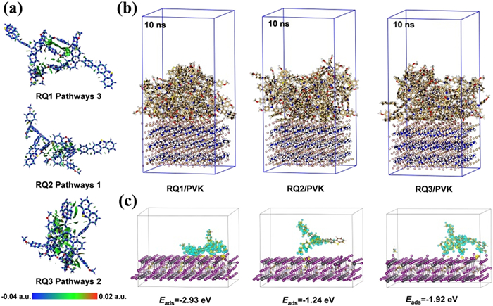
(a) Graphical representation of the interactions in the pathways within RQ1–RQ3, each with their respective maximum vh. (b) The MD simulations of the adsorption morphology of RQ1–RQ3 on the perovskite surface. (c) The interfacial charge transfer of the extracted individual RQ1–RQ3 with perovskite was simulated after MD simulations.
The intermolecular interactions in these pathways were precisely quantified using energy decomposition analysis (EDA). As shown in Table S1 (Supporting information), the calculated trend for the total interaction energy (ΔEint) is RQ3 (−34.56 kcal/mol) > RQ1 (−21.08 kcal/mol) > RQ2 (−14.65 kcal/mol). The exchange-repulsion interaction (ΔExrep) and Coulomb interaction (ΔEc) between the three molecular fragments are primarily determined by intermolecular distance; as ri decreases, ΔExrep and ΔEc increase significantly [32]. Compared to RQ2 and RQ3, the proportion of orbital interaction energy (ΔEorb) to the total attractive interaction energy in RQ1 is higher, with a trend of RQ1 (13.88%) > RQ3 (13.17%) > RQ2 (12.58%). This indicates that in RQ1 Pathways 3, orbital interactions play a stronger role in charge transfer and covalent bonding [33]. This provides evidence of intermolecular π-π interactions, facilitating hole hopping between molecules and explaining the different vh observed in these pathways. Although the magnitudes of electrostatic interaction energy (ΔEels) and ΔEorb in RQ3 Pathways 2 are significantly increased, the increase in ΔExrep is more pronounced, reflecting the particularly strong steric hindrance effects in RQ3 Pathways 2 [34].
As shown in Fig. 2b, MD simulations were employed to analyze the interface adsorption between perovskite and HTMs. The time-total energy curves obtained from MD simulations are shown in Fig. S3 (Supporting information). The results indicate that after approximately 2 ns of equilibration, the total energy of these systems begins to stabilize, suggesting that equilibrium has been achieved. After 10 ns of simulation, RQ1–RQ3 molecules adhered closely to the perovskite surface. The average dihedral angles of 24 RQ1–RQ3 molecules relative to the perovskite plane were calculated, yielding the following trend: RQ2 (46.40°) > RQ3 (46.31°) > RQ1 (37.35°). This indicates that RQ1 exhibits a flatter average adsorption morphology on the perovskite surface, suggesting stronger adsorption [35]. Based on the final adsorption configurations obtained from the MD simulations, first-principles calculations were conducted to investigate the charge transfer between the HTM and the perovskite layer. As shown in Fig. 2c, charge transfer from the perovskite to the HTM molecules occurs throughout almost the entire HTM, demonstrating their potential for efficient hole extraction from the perovskite [36]. Notably, RQ1 exhibited the highest adsorption energy (−2.93 eV) and strong charge transfer interactions between the DBT plane and the perovskite, highlighting the Lewis base character of DBT.
The isomers RQ1–RQ3, featuring dibenzothiophene substituents, demonstrate appropriate energy alignment with the perovskite energy levels and exhibit Lewis basicity. Notably, the designed RQ1 shows excellent hole mobility and stronger interfacial interactions in perovskite/HTM interface simulations. Therefore, among these three molecules, RQ1 is a promising candidate for an efficient HTM in PSCs.
To confirm the theoretical results and obtain alternative HTMs, RQ1–RQ3 were synthesized through a simple synthetic route, as shown in Fig. S4 (Supporting information). Detailed experimental procedures can be found in Supporting information. The chemical structures of the HTMs were identified by 1H NMR, 13C NMR, and HRMS characterization (Figs. S5–S13 in Supporting information).
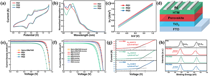
The electrochemical and optical properties of these HTMs in CCl2H2 solution were investigated using cyclic voltammetry (CV) and UV-vis spectroscopy. As shown in Figs. 3a and b and summarized in Table 3, RQ1–RQ3 exhibit strong absorption below 350 nm, while the weak absorption between 350 nm and 440 nm can be attributed to partial charge transfer from diphenylamine to carbazole. The strong absorption below 350 nm is primarily due to π–π* transitions within the carbazole and diphenylamine units [37]. The maximum absorption peaks (λmax) for RQ1, RQ2, and RQ3 are 421, 421, and 418 nm, respectively. The optical band gaps (Eg), estimated from the onset wavelengths (λonset) of absorption, are all approximately 2.82 eV. CV measurements indicated that the HOMO energy levels of RQ1, RQ2, and RQ3 are −5.15, −5.15, and −5.13 eV, respectively. Based on the Eg and HOMO values, the LUMO energy levels of the three isomers were estimated to be −2.33, −2.33, and −2.31 eV, respectively. These frontier energy levels of the HTMs matching well with those of the perovskite. Fig. 3c and Table 3 display the hole mobilities of pure hole-only devices containing RQ1–RQ3, measured using space-charge limited current (SCLC) techniques [38,39]. The film thicknesses of RQ1, RQ2 and RQ3 are 124, 121, and 126 nm, respectively. The hole mobilities are ordered as follows: RQ1 (7.26 × 10⁻⁴ cm2 V−1 s−1) > RQ3 (6.96 × 10⁻⁴ cm2 V−1 s−1) > RQ2 (5.60 × 10⁻⁴ cm2 V−1 s−1), which is consistent with our simulation predictions.
Figure 3
Figure 3.
(a) Cyclic voltammogram (CV) curves. (b) Measured absorption spectra of RQ1–RQ3 in CCl2H2 solution. (c) J-V characteristics used to measure the hole mobility of RQ1–RQ3. (d) PSC device composition diagram. (e) J-V curves of the optimal devices based on RQ1–RQ3 and Spiro-OMeTAD. (f) J-V curves of the minimal hysteresis PSCs based on RQ1–RQ3 and Spiro-OMeTAD. (g) SCLC plots of the hole-only devices displaying VTFL kink point behaviors based on RQ1–RQ3. (h) Pb 4f peaks of the pristine perovskite film, and perovskite film coated with RQ1–RQ3-based HTMs layers.
a Absorption spectra were measured in dichloromethane solution. b Optical band gap (Eg) obtained from the onset values of absorption (λonset). c Onset of oxidation potentials measured by cyclovoltammetry.
Based on the device structure shown in Fig. 3d, PSCs were fabricated using RQ1–RQ3 as HTL, and their photovoltaic performance was characterized. According to the statistical data from 20 devices (Table 4), the trend of the average and maximum PCEs is as follows: RQ1 (22.89% ± 0.42%, 23.50%) > RQ3 (21.99% ± 0.26%, 22.56%) > RQ2 (17.83% ± 0.39%, 18.69%). The current density-voltage (J-V) curves of the best-performing devices based on RQ1–RQ3 are shown in Fig. 3e. The device with RQ1 achieved a Jsc of 24.91 mA/cm2, a Voc of 1.143 V, FF of 82.54%, and a PCE of 23.50%. The device with RQ2 exhibited the lowest PCE of 18.69%. Notably, the device with RQ3 showed a commendable PCE of 22.56%, a Jsc of 24.69 mA/cm2, a Voc of 1.143 V, and FF of 79.94%.
Table 4
Table 4.
Photovoltaic parameters of RQ1–RQ3 and Spiro-OMeTAD based PSC devices.
a The maximum value. b The average value were obtained from 20 devices.
The enhanced performance of RQ1 is primarily attributed to the simultaneous improvement in Jsc, Voc, and FF, which is mainly due to its higher hole mobility and stronger intermolecular and interfacial interactions. Comparative performance tests with the classical Spiro-OMeTAD molecule were conducted (Fig. 3e and Table 4). Under the same conditions, devices based on Spiro-OMeTAD achieved a slightly lower PCE of 22.47%, with a Jsc of 24.90 mA/cm2, a Voc of 1.135 V, and FF of 79.51%.
As shown in Fig. S14 (Supporting information), among the 20 tested devices, the RQ1-based devices exhibited a narrower PCE distribution in the box plot and outperformed the devices based on RQ2, RQ3, or Spiro-OMeTAD, primarily due to the improvements in Voc and FF. Stability tests were conducted on non-encapsulated PSC devices using RQ1–RQ3 and Spiro-OMeTAD as HTMs in a glovebox under an N2 atmosphere. As shown in Fig. S15 (Supporting information), after more than 1000 h under N2 conditions, devices based on Spiro-OMeTAD and RQ1 demonstrated good stability, retaining about 90% of their initial PCE, significantly higher than those based on RQ2 and RQ3.After a comprehensive characterization of the photovoltaic performance and stability of the devices, it can be concluded that devices based on RQ1 exhibit high PCE, stable performance, and reproducibility, making RQ1 an ideal HTM candidate to improve the photovoltaic performance and stability of PSC devices as a replacement for the traditional Spiro-OMeTAD [40].
To gain a deeper understanding of the photovoltaic performance differences among RQ1–RQ3 in PSCs, the defect state density was determined using the SCLC method. As shown in Fig. 3g, the fitted trap-filled limit voltage (VTFL) for devices based on RQ1–RQ3 were 0.317, 0.618, and 0.369 V, respectively, with corresponding calculated defect densities of 3.11 × 10¹⁵, 6.07 × 10¹⁵, and 3.63 × 1015 cm−3. The lower defect state density in RQ1-based devices reduces non-radiative recombination at the perovskite/HTMs interface, resulting in higher open-circuit voltage [41]. X-ray photoelectron spectroscopy (XPS) was used to investigate the interactions at the RQ1–RQ3/perovskite interface. As shown in Fig. 3h, two main peaks at 137.91 and 142.75 eV, corresponding to Pb 4f7/2 and 4f5/2 orbitals, respectively, were observed in the bare perovskite film. Upon adsorption of RQ1–RQ3, both peaks for RQ1 and RQ3 shifted to lower binding energies, with a more significant shift for the RQ1/perovskite interface, indicating a stronger interaction between RQ1 and Pb [41].
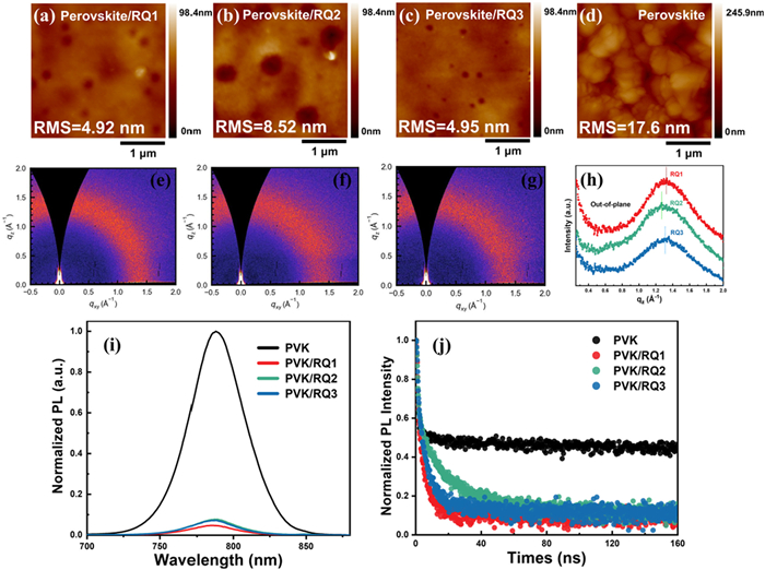
To evaluate the morphology of RQ1–RQ3 films on perovskite, atomic force microscopy (AFM) was employed to image these films. As shown in Figs. 4a–d, the root mean square (RMS) roughness of RQ1–RQ3/perovskite films were 4.92, 8.52, and 4.95 nm, respectively, which are significantly lower than that of the bare perovskite film (RMS = 17.6 nm). RQ2 exhibited a rough and uneven morphology, while RQ1 showed the smoothest and most compact surface, indicating the best interfacial contact between the perovskite layer and the HTM layer. This smooth and dense morphology of RQ1 contributes to its enhanced charge extraction capability and improved device stability [42].
Figure 4
Figure 4.
(a–d) AFM image of perovskite film and RQ1–RQ3 film on the perovskites. (e–g) GIWAXS patterns of RQ1–RQ3 coated on Si. (h) 1D line-cut profiles from GIWAXS patterns. (i) Steady-state PL spectra of the perovskite films, RQ1–RQ3 film on the perovskites. (j) Time-resolved PL decay of the perovskite films, RQ1–RQ3 film on the perovskites.
Grazing-incidence wide-angle X-ray scattering (GIWAXS) was performed on the three HTM films [43]. As illustrated in Figs. 4e–g, RQ1–RQ3 displayed broad diffraction peaks at approximately 1.0–1.8 Å−1, attributed to π–π stacking, indicating that their films are amorphous [44]. In Fig. 4h, the peak position for the RQ1 film is at 1.33 Å−1, whereas RQ2 and RQ3 have peak positions at 1.27 and 1.31 Å−1, respectively. This suggests that the π–π stacking distance for RQ1 (4.72 Å) is shorter than that for RQ2 (4.95 Å) and RQ3 (4.80 Å) [45]. This indicates that adjusting the intermolecular interaction patterns of HTMs through side-chain DBT isomerization facilitates molecular stacking, thereby improving charge transport properties and device performance.
The photogenerated hole dynamics can be characterised by steady-state photoluminescence (PL) and time-resolved photoluminescence (TRPL). As can be seen in Fig. 4i, the steady-state PL emission peak of bare perovskite is located at 790 nm, and the PL intensity drops sharply to < 10% after spin-coating HTMs. The trend in PL intensity is RQ1 < RQ3 < RQ2, and the quenching effect is more pronounced in RQ1, indicating that RQ1 is more effective in extracting holes among the three molecules [46,47]. Subsequently, TRPL measurements were performed. As shown in Fig. 4j, the film lifetime decreased rapidly after spinning the HTMs, and the trend for the three isomeric molecules is RQ1 < RQ3 < RQ2. The shortest lifetime of the perovskite/RQ1 film reflects the reduction of non-radiative charge recombination at the perovskite/RQ1 interface and the optimal hole extraction process [48]. Therefore, this enhanced hole-extraction ability and reduced non-radiative recombination can be achieved by changing the substituent position of the side chain.
This study investigates and elucidates the impact of regioisomeric side-chain structural variations in HTMs on the performance of PSCs. Through DFT, MD, and first-principles calculations, the interaction patterns of these HTMs in PSC applications were comprehensively examined. Simulations indicate that although the isomers RQ1–RQ3 share similar frontier molecular orbital properties and optical characteristics, the alteration in the substitution position of the DBT group enhances orbital interactions of RQ1, making charge transfer and covalent interactions more pronounced, with effective intermolecular π–π interactions. Additionally, RQ1 exhibits a flatter macroscopic adsorption and enhanced interfacial charge transfer on perovskite. The designed RQ1–RQ3 were synthesized and integrated into PSC devices to validate the theoretical findings and computational models. PSCs based on RQ1 demonstrated superior performance, achieving an efficiency of 23.50%, which is higher than those based on the other isomers RQ2 (18.69%) and RQ3 (22.56%) under identical conditions. This improvement is attributed to its favorable film morphology, enhanced intermolecular π–π stacking and hole mobility, capability to passivate interfacial defects, and suppression of non-radiative recombination in perovskite. The experimental results corroborated the accuracy of the computational models and provided new insights into designing viable HTM candidates by manipulating the substituent positions in the side chains.
Declaration of competing interest
The authors declare that they have no known competing financial interests or personal relationships that could have appeared to influence the work reported in this paper.
CRediT authorship contribution statement
Ruiqin Wang: Writing – original draft, Methodology, Investigation, Data curation. Lei Yang: Methodology, Investigation, Data curation. Jiayi Qi: Investigation. Xin Chen: Investigation. Ming Li: Software, Resources. Yong Hua: Validation, Supervision, Investigation. Rongxing He: Validation, Supervision, Resources. Xiaorui Liu: Writing – review & editing, Supervision, Project administration, Investigation, Funding acquisition, Conceptualization.
Acknowledgment
This work was supported by supported by Chengdu Key Research and Development Program (No. 2023-YF11-00027-HZ), Fundamental Research Funds for the Central Universities (Nos. SWU-KT23009, SWU-XDJH202314).
Supplementary materials
Supplementary material associated with this article can be found, in the online version, at doi:10.1016/j.cclet.2025.110891.
Z. Xu, D.D. Astridge, R.A. Kerner, et al., J. Am. Chem. Soc. 145 (2023) 11846–11858. doi: 10.1021/jacs.3c03539
[47]
S. Akel, Y. Wang, G. Yan, U. Rau, T. Kirchartz, Adv. Energy Mater. 14 (2024) 2401800. doi: 10.1002/aenm.202401800
[48]
R. Tang, H. Liu, Y. Xu, et al., Adv. Funct. Mater. 33 (2022) 2208859.
Figure 1
(a) Chemical structures and the schematic diagram of the frontier molecular orbitals for three isomeric molecules in this study. (b) Electrostatic surface potential (ESP) images of RQ1–RQ3. (c) After simulating for 10 ns using MD methods, the final morphologies of RQ1–RQ3 and main charge hopping pathways extracted.
Figure 2
(a) Graphical representation of the interactions in the pathways within RQ1–RQ3, each with their respective maximum vh. (b) The MD simulations of the adsorption morphology of RQ1–RQ3 on the perovskite surface. (c) The interfacial charge transfer of the extracted individual RQ1–RQ3 with perovskite was simulated after MD simulations.
Figure 3
(a) Cyclic voltammogram (CV) curves. (b) Measured absorption spectra of RQ1–RQ3 in CCl2H2 solution. (c) J-V characteristics used to measure the hole mobility of RQ1–RQ3. (d) PSC device composition diagram. (e) J-V curves of the optimal devices based on RQ1–RQ3 and Spiro-OMeTAD. (f) J-V curves of the minimal hysteresis PSCs based on RQ1–RQ3 and Spiro-OMeTAD. (g) SCLC plots of the hole-only devices displaying VTFL kink point behaviors based on RQ1–RQ3. (h) Pb 4f peaks of the pristine perovskite film, and perovskite film coated with RQ1–RQ3-based HTMs layers.
Figure 4
(a–d) AFM image of perovskite film and RQ1–RQ3 film on the perovskites. (e–g) GIWAXS patterns of RQ1–RQ3 coated on Si. (h) 1D line-cut profiles from GIWAXS patterns. (i) Steady-state PL spectra of the perovskite films, RQ1–RQ3 film on the perovskites. (j) Time-resolved PL decay of the perovskite films, RQ1–RQ3 film on the perovskites.
Table 2.
The reorganization energy λ (eV), charge transfer integral vh (eV), hole transport rate kij (s−1), center-of-mass distance ri (Å) and hole mobility uh (cm2 V−1 s−1) of main hopping pathway selected on basis of the MD simulations for RQ1–RQ3.
Table 3.
Experimental results such as optical properties, HOMO/LUMO energy and hole mobility of RQ1–RQ3.
HTM
λmaxa (nm)
λonset (nm)
Egb (eV)
Eoxc (eV)
HOMO (eV)
LUMO (eV)
Hole mobility (cm2 V−1 s−1)
RQ1
421
439
2.82
0.40
−5.15
−2.33
7.26 × 10⁻⁴
RQ2
421
439
2.82
0.40
−5.15
−2.33
5.60 × 10⁻⁴
RQ3
418
439
2.82
0.42
−5.13
−2.31
6.96 × 10⁻⁴
a Absorption spectra were measured in dichloromethane solution. b Optical band gap (Eg) obtained from the onset values of absorption (λonset). c Onset of oxidation potentials measured by cyclovoltammetry.

 DownLoad:

 下载:
下载:


 下载:
下载:
