Received Date:
01 November 2024 Accepted Date:
11 December 2024 Revised Date:
01 December 2024 Available Online:
15 April 2026
Abstract:
Lithium-ion batteries (LIBs) are essential energy storage devices widely used in portable electronics, transportation, and various other applications. However, current anode materials, with their low intercalation potentials and poor rate performance, struggle to balance energy density, power density, and safety, particularly under extreme conditions. In this work, we report a self-regulating micro-channel network that forms a three-dimensional (3D) composite electrode architecture without binders and conductive additives, offering a promising anode solution for fast-charging LIBs. Benefiting from the robust 3D architecture with abundant Li+ active sites and superior electronic conductivity, the niobium tungsten oxide@carbon nanotube (NWO/CNT) composite electrode demonstrates a high reversible capacity (246.6 mAh/g at 0.2 C), excellent rate capability (117.1 mAh/g at 60 C), and long-term durability (73.0% capacity retention after 10,000 cycles). Additionally, a thick electrode with high mass loading (10 mg/cm2) shows remarkable high-rate performance, retaining 51.7% capacity at 20 C. Notably, when paired with LiFePO4 (LFP) cathodes, the NWO@CNT//LFP@CNT full batteries exhibit impressive high-power capability (2.8 kW/kg), high energy density (394.2 Wh/kg), and exceptional cycle stability (82% capacity retention after 6000 cycles). Most importantly, this composite electrode architecture also enables the fabrication of a planar, miniaturized, all-solid-state lithium-ion battery with fast-charging capabilities.
Lithium-ion batteries have mainly dominated the market for powering portable electronic devices, electric vehicles, and grid storage [1–5]. However, increasing technological demands call for energy storage devices that provide both higher energy density and the ability to recharge within 10–15 min, offering fast-charging capabilities [6–9]. The pressure to meet these goals has spurred scientific research on electrode structures with enhanced charge transport (both electrons and ions transport) capabilities [10–12]. An optimized structure enables rapid transport of both ions and electrons throughout the entire electrode, ensuring efficient utilization of all active material [13–15]. A key strategy to achieve this is optimizing the electrode structure to maximize electrode area loading (C/A), thereby increasing energy density [16,17]. The relationship is expressed as C/A = Csp × M/A, where Csp is the specific capacity of the electrode material (mAh/g), and M/A is the mass loading (g/cm2) [18–20]. To maximize both Csp and M/A, the material must achieve a thicker mass loading (~10 mg/cm2), which poses a significant challenge for nanoscale materials or conventional thin electrodes (~1 mg/cm2) [21]. Moreover, thick electrodes suffer from limited ion diffusion, and even when nanomaterials are combined with polymer binders, they are prone to cracking due to poor mechanical strength, preventing the formation of thick layers [18,22,23]. Additionally, the uneven distribution of traditional acetylene black additives results in unstable electrode conductivity, limiting electrochemical performance [24–27].
Furthermore, to enable fast-charging capabilities, improving rate performance of electrode materials is the most direct approach to enhancing the high-power characteristics of LIBs [28–33]. Currently, the most common methods for improving rate performance include: (1) Nano-sizing electrode materials or designing porous (or layered) structures to shorten the lithium-ion diffusion path within the composite electrode, facilitating rapid ion migration while increasing the surface area for interaction between the electrode material and the electrolyte [34–40] (2) Preparing hierarchical porous carbon composites or carbon-coated electrodes to improve conductivity, a crucial requirement for high-rate operation of certain electrode materials [13,41–43]. However, there are inherent drawbacks to using nanosized or porous materials for energy storage. First, the synthesis, characterization, and industrialization of these materials are time-consuming, resulting in relatively high costs [44–46]. Second, the production methods often have low yields and generate significant chemical waste [47–49]. Third, during electrochemical cycling, the structure of these materials tends to degrade upon contact with the electrolyte, leading to a collapse of the electrode and a reduction in its volumetric energy density [50,51].
In this contribution, we synthesized high-loading electrode materials by utilizing non-traditional material sizes as well as incorporating micro-channels network structure to enhance fast charging capability, which overcome the limitations of traditional nanoscale electrode materials and could achieve thicker or free-standing electrode materials. Specifically, instead of conventional conductive additives like acetylene black or Super P, we use a slurry of aqueous single-walled carbon nanotubes (SWCNTs) as a replacement. Additionally, we eliminate the need for traditional polymer binders, such as polyvinylidene difluoride (PVDF), sodium carboxymethyl cellulose, poly(tetrafluoroethylene), or polyvinylpyrrolidone, opting for a composite structure that integrates bulk niobium tungsten oxide (NWO) with aqueous SWCNTs network. This approach enables the construction of a high-mass loading electrode structure (~10 mg/cm2) with excellent mechanical and electrochemical properties, significantly increasing the critical rupture thickness of the electrode. Electrochemical testing of composite electrodes in LIBs demonstrated exceptional rate performance and a marked improvement in specific capacity. Even with a dispersion of slurry content as low as 0.5 wt%, an effective electrode structure was maintained. Remarkably, at a cycling rate of 1 C, the specific capacity remained at 205.8 mAh/g. Kinetic analysis of the electrochemical reactions revealed that the enhanced capacity of the constructed electrode structure was primarily attributed to redox pseudocapacitance.
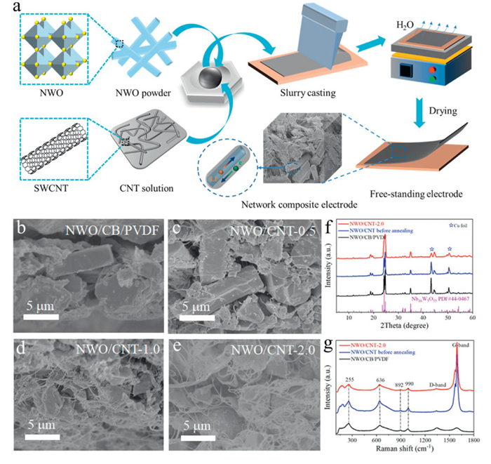
Niobium tungsten oxide material (Nb16W5O55, abbreviated as NWO), holds a great perspective on the development of thick electrodes with high energy densities without compromising power densities. To maximize its performance, aqueous single-walled carbon nanotubes as the conductive scaffolds were incorporated into the electrodes to enhance conductivity and toughness. As shown in Fig. 1a, the blade coating method mixing carbon nanotube dispersion slurry is an effective and scalable technology to fabricate cross-linked composite electrode, forming a 3D segregated micro-channels network porous architecture [52]. NWO and aqueous SWCNTs slurry are mixed and ground to form a homogenous slurry in an agate mortar, integrating the respective advantages of micrometre-sized particles and nanomaterials with high specific capacity (maximum theoretical gravimetric capacity of 342.6 mAh/g and volumetric capacity of 1770.6 mAh/cm3, respectively) and superior electronic conductivity [53]. Subsequently, the mixture slurry was produced directly on the spread copper foil substrate by using a spatula. And then transferred composited electrode onto heating plate with the temperature of 80 ℃ to immediately remove the adsorbed moisture in the electrode. It is worth mentioning that when the amount of carbon nanotubes is increased to a certain amount, the composite electrode can be separated from the current collector of the copper and become a free-standing electrode. Compared to the traditional coated method using the conductive additive such as carbon black and PVDF binder, the single-walled carbon nanotube dispersion slurry possesses the lower crystalline and toughens the mechanical stability of the composite electrode to form into robust electrode.
Figure 1
Figure 1.
(a) Schematic illustrating the fabrication of the cross-linked NWO/CNT composite electrode architectures and its unique rapid ion/electron transportation paths. The electrode comparison of the traditional coating material and hierarchical NWO/CNT composite materials: The cross-sectional SEM images of (b) the electrode using conventional coating method, and (c–e) the hierarchical NWO/CNT composite electrode architectures with CNT mass fraction ranging from 0.5 wt% to 2.0 wt%. (f) The XRD patterns and (g) Raman spectra for the traditional electrode and the hierarchical composite electrode before/after annealing.
As shown in Fig. 1b, the cross-sectional field emission scanning electron microscopy (FE-SEM) images show that the traditional electrode coated with acetylene black and a PVDF binder appears relatively dense. In contrast, the electrode composed of CNT aqueous dispersion, with different mass fractions added to niobium tungsten oxide, exhibits a 3D hierarchical porous structure (Figs. 1c–e). This structure is highly conducive to electrolyte infiltration, promoting faster electron and ion transport within the electrode. X-ray diffraction (XRD) characterization of both the traditional coated electrode and the composite electrodes containing carbon nanotubes (NWO/CNT-2.0, the mass fraction of CNT: 2.0 wt%) was performed before and after annealing. The results showed that the crystal structure and morphological characteristics of the raw materials remained intact throughout the coating and annealing processes (Fig. 1f and Fig. S1 in Supporting information). Notably, the characteristic peak of the copper current collector is weakened in the NWO/CNT-2.0 electrode, indicating an increase in electrode thickness due to the carbon nanotube coating, as further confirmed by the cross-sectional view of the electrode (Fig. S2 in Supporting information). Furthermore, Raman spectra was utilized to analyze the traditional and composite electrodes in these cases. The characteristic peaks below 1200 cm−1 are primarily attributed to the (Nb, W)6 octahedron, the Nb(W)-O bond in the (Nb, W)4 tetrahedron, and the symmetric stretching vibrations of metal-metal bonds in niobium tungsten oxide materials. The peaks above 1200 cm−1 correspond to the D and G bands of carbon nanotubes in the composite electrodes, with the G peak of the carbon nanotubes appearing notably sharper (Fig. 1g).
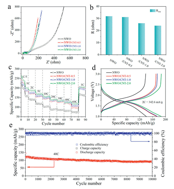
To evaluate the lithium storage performance of the 3D porous NWO/CNT composite electrode, this composite architecture electrode was assembled into a LIBs for basic electrochemical measurements, compared with the traditional coating electrode. As shown in Figs. 2a and b, the traditional coating method results in high ion diffusion impedance. In contrast, composite electrodes significantly reduce ion diffusion impedance, indicating that the NWO/CNT porous structure facilitates more efficient Li⁺ ions diffusion. Additionally, for charge transfer impedance, as the carbon nanotube content increases (ranging from 0.5 wt% to 2.0 wt%), the ionic diffusion resistance gradually decreases, with values ranging from 31.8 Ω to 24.8 Ω. Fig. S3 (Supporting information) shows the simulation results from the electrochemical impedance spectroscopy (EIS) test, with the equivalent circuit diagram presented in the inset of Fig. S3a. To further demonstrate the superior lithium storage capabilities of the niobium tungsten oxide@carbon nanotube composite electrode architecture, the rate performance of the composite electrodes was tested. It was observed that as the mass fraction of carbon nanotubes increased (0.5, 1.0, and 2.0 wt%), both the specific capacity and rate performance improved significantly compared to the traditional coating electrodes. This enhancement is primarily due to the uniform coating of niobium tungsten oxide by single-walled carbon nanotubes slurry, which effectively increases the conductivity of the bimetallic oxide electrode. As shown in Figs. 2c and d, for the NWO/CNT-2.0 batteries, the specific capacities at current densities ranging from 0.2 C to 60 C are 264.1, 236.3, 187.2, 169.9, 154.1, 139.1, 134.2, 125.6, and 117.1 mAh/g, respectively. Even when cycled current density returns at 1 C, the capacity remains at 205.8 mAh/g. In contrast, for electrodes coated using the traditional method, the specific capacities at the same current densities are 224.6, 194.0, 140.8, 120.0, 102.7, 89.4, 84.2, 81.8, and 74.3 mAh/g, respectively, with a capacity retention of 168 mAh/g when the current density returns to 1 C. Although the traditional coating method electrode also demonstrates good rate performance, the specific capacity of rate performance is significantly lower than that of the NWO/CNT composite electrodes. To further characterize the stability of NWO/CNT composite architecture electrode, a cycle stability test of NWO/CNT-2.0 was conducted (Fig. 2e). At a high current density of 40 C, the composite electrode maintained stable cycling for 10,000 cycles with a capacity retention rate of 73%. Additionally, the capacity retention rate remained at 81.9% after 5000 cycles, further highlighting the exceptional stability of niobium tungsten oxide@carbon nanotube composite architectures.
Figure 2
Figure 2.
The electrochemical performance comparison of the traditional coating method electrode and hierarchical composite electrodes in LIBs. (a) The comparison of electrochemical impedance spectroscopy obtained after 5 cycles test. (b) The ionic diffusion resistance (Rion) value corresponding to the different electrode architectures. (c) The rate performance comparison using the total mass of electrodes at various rate (C/5 to 60 C) for the traditional coating electrode and hierarchical composite electrodes. (d) The galvanostatic charge-discharge curves of the traditional electrode and hierarchical composite electrodes at a rate of 2 C. (e) The cycling performance and Coulombic efficiency for hierarchical composite electrode with 2.0 wt% CNT at 40 C.
To investigate the lithium storage kinetics of the niobium tungsten oxide@carbon nanotube composite electrode, cyclic voltammetry (CV) was conducted at various scan rates (0.2–50 mV/s). As shown in Figs. S4a and b (Supporting information), the Li+ storage behavior of this composite electrode structure closely resembles that of an electrode fabricated using the traditional coating method, with both relying on the ion intercalation process near the electrode surface and accompanied by niobium and tungsten redox pseudocapacitance. Calculations of i = avb [54], depicted in Figs. S4c and d (Supporting information), reveal that at scan rates of 0.2–5.0 mV/s, the b values for both electrodes are approximately 0.94 and 0.95, respectively. However, as the scan rate increases to 5–50 mV/s, the b values decrease consistently to 0.67 and 0.68, indicating a reaction process primarily controlled by surface redox pseudocapacitance and partial diffusion pseudocapacitance. Additionally, the inclusion of carbon nanotubes enhances the Li+ transport rate without altering the intrinsic redox pseudocapacitive properties of niobium tungsten oxide during Li+ insertion and extraction.
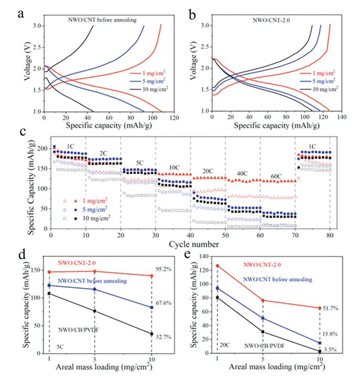
The constant current charge-discharge and rate performance of electrodes coated using the traditional method, as well as the NWO/CNT composite electrode before and after annealing, were studied under different area mass loading conditions. Before annealing, as shown in Fig. 3a, the NWO/CNT composite electrode exhibited a specific capacity of 109.2 mAh/g at 1 mg/cm2, but under high loading conditions (10 mg/cm2), the capacity attenuated to 45.8 mAh/g. This suggests that the annealing process is critical for removing dispersants from the carbon nanotubes. After annealing, as shown in Fig. 3b, the composite electrode achieved a specific capacity of 126.8 mAh/g at 1 mg/cm2, and an improved capacity of 108.4 mAh/g under a high load of 10 mg/cm2. For the rate performance test (Fig. 3c), electrodes containing only niobium tungsten oxide and carbon nanotubes—without other impurities—demonstrated excellent rate performance at high current densities (60 C), whereas electrodes containing binders and dispersants showed poorer performance. This indicates that eliminating binders and dispersants significantly improves rate performance of LIBs, enabling fast-charging capabilities. As further illustrated in Figs. 3d and e, at a current density of 5 C, the capacity retention rates of niobium tungsten oxide before and after annealing were 32.7%, 67.6%, and 95.2% under different loadings. At a higher current density (20 C), the annealed composite electrode achieved a capacity retention rate of 51.7%, while the other two cases exhibited significantly lower retention rates of 15.8% and 3.5%. This highlights the importance of optimizing electrode loading when designing fast-charging lithium-ion batteries.
Figure 3
Figure 3.
Comparison of rate performance before and after annealing of conventional electrode and composite electrode under high mass loading conditions. (a) GCD curves of NWO/CNT composite electrode before annealing. (b) GCD curves of NWO/CNT composite electrode after annealing. (c) Comparison of rate performance under different area mass loading (1, 5 and 10 mg/cm2) for conventional electrode (open) and composite electrode (solid). Capacity retention of conventional electrodes and NWO/CNT composite electrodes before and after annealing, (d) at the current density of 5 C, (e) at the current density of 20 C.
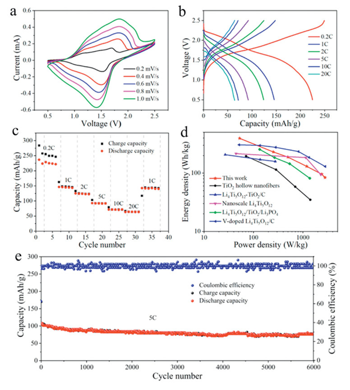
For the lithium-ion full battery, the negative electrode composed of niobium tungsten oxide@carbon nanotube composite was paired with a commercially purchased LiFePO4 cathode, which was also fabricated using a composite method by incorporating single-walled carbon nanotube aqueous dispersion (Fig. S5 in Supporting information). The electrochemical window of the full battery ranges from 0.5 V to 2.5 V, with the lower voltage limit primarily attributed to the relatively low potential of the LiFePO4 cathode (2.5–4.2 V vs. Li/Li⁺). Among the available options for positive electrodes in lithium-ion batteries, LiFePO4 stands out as one of the few materials suitable for fast charging. As illustrated in Fig. 4a, the CV curves of the full battery reveal a pair of distinct redox peaks at 1.4 V and 1.8 V. This indicates that the full battery operates primarily through a redox pseudocapacitive reaction at the Nb16W5O55 anode and a lithium-ion intercalation reaction at the LiFePO4 cathode. Figs. 4b and c demonstrate the rate performance of the Nb16W5O55@CNT//LiFePO4@CNT full battery, with specific capacities of 221.8, 145.9, 124.1, 92.3, 71.6, and 63.6 mAh/g at current densities ranging from 0.2 C to 20 C. Notably, when the current density is returned to 1 C, the full battery maintains a capacity of 141.8 mAh/g. In comparison with traditional lithium-ion batteries, which utilize LiFePO4 as cathode and TiO2 hollow nanowires anode, Li4Ti5O12-TiO2/C composite anode, nano-sized Li4Ti5O12 anode, Li4Ti5O12/TiO2/Li3PO4 composite electrodes, or V-doped Li4Ti5O12/C composite anodes, the assembled Nb16W5O55@CNT//LiFePO4@CNT full battery exhibits a high energy density of 394.2 Wh/kg and a power density of 2.8 kW/kg (Fig. 4d). Further cycling stability evaluation of the full battery demonstrated that at a current density of 5 C, the initial specific capacity was 106.3 mAh/g, and it could be cycled stably for 6000 cycles with a capacity retention rate of 73.1% (Fig. 4e). After 1000 cycles, the capacity retention rate was recorded at 82%. Fig. S6 (Supporting information) shows the electrochemical impedance characteristics of the Nb16W5O55@CNT//LiFePO4@CNT full battery, indicating a low charge transfer impedance value of 23.8 Ω. Moreover, Fig. S7 (Supporting information) illustrates that matching the masses of the positive and negative electrodes, specifically a negative electrode mass to positive electrode mass ratio of 1:1.3, results in enhanced specific capacity and cycling stability.
Figure 4
Figure 4.
The full batteries electrochemical performance of niobium tungsten oxide@carbon nanotube (Nb16W5O55@CNT) composite anodes and LiFePO4@carbon nanotube (LiFePO4@CNT) composite cathodes: (a) CV curves. (b) GCD curves at different current densities. (c) Full cell rate performance. (d) Ragone plot comparison of the high-rate Nb16W5O55@CNT anode with reported anodes paired with LFP cathodes from the previous literature [50]. (e) Cyclic stability test at 5 C.
In addition, when the CNT content in the electrode reaches 4.0 wt%, the active materials of both the positive and negative electrodes can detach from the copper current collector, forming free-standing electrode sheets without needing a current collector. These electrode sheets maintain excellent electrochemical properties. Thus, it is feasible to coat the Nb16W5O55@CNT negative electrode and LiFePO4@CNT positive electrode onto non-metallic substrates, such as copy paper, filter paper, wood, or fabric, to create a planar, miniaturized, fast-charging lithium-ion battery, thereby expanding potential application scenarios. Under current laboratory conditions, as shown in Fig. S8 (Supporting information), filter paper was selected as the substrate for electrode coating. This design allows the electrode to bend without shedding, making it well-suited for flexible, miniaturized devices. To develop an all-solid-state Li battery, an all-solid-state lithium bis(trifluoromethanesulfonyl)imide- 1-butyl-1-methylpyrrolidinium bis(trifluoromethanesulfonyl)imide-polyvinylidene fluoride-co-hexafluoropropylene (LiTFSI-Py14TFSI-HFP) gel electrolyte was synthesized (Fig. S9 in Supporting information). This electrolyte was applied to the planar electrode, and copper tape was used to connect the electrode leads on both sides, with polyimide tape for packaging (Fig. S10 in Supporting information). Cycle performance testing showed that this planar miniaturized LIBs remains stable over 2000 cycles at the current density of 0.4 mA/cm2 (Fig. S11 in Supporting information). Additionally, multimeter measurements of the coated electrodes revealed a maximum resistance of 491 Ω on the positive electrode plane and 310 Ω on the negative electrode plane (Fig. S12 in Supporting information). These low resistance values are advantageous for electron transport. Notably, the design ensures no contact between the positive and negative electrodes, resulting in a successful planar, flexible, all-solid-state battery configuration.
In summary, the development of high-rate negative electrode materials is critical for enabling fast-charging lithium-ion batteries. By constructing a three-dimensional porous composite electrode of niobium tungsten oxide material integrated with single-walled carbon nanotubes, more efficient transport of charge carriers can be achieved. The incorporation of CNTs enhances the mechanical properties and conductivity of the niobium tungsten oxide, with optimal performance observed at a CNT content of 2.0%. At this composition, the electrode delivers specific capacities of 264.1 mAh/g at 0.2 C and 117.1 mAh/g at 60 C. Moreover, the Nb16W5O55@CNT composite electrode demonstrates excellent cycling stability, retaining 73% of its capacity after 10,000 cycles. Even in thicker electrodes (10 mg/cm2), the electrode maintains a high-rate performance, with a 95.2% retention rate at the current density of 5 C. In full lithium-ion cells, combining the Nb16W5O55@CNT anode with a LiFePO4@CNT cathode results in high-rate performance and a specific capacity of 63.6 mAh/g at 20 C. When the mass fraction of CNTs in both positive and negative electrodes is increased, the electrodes can be separated from the current collector, making them free-standing electrode. This allowed for the development of a planar, miniaturized all-solid-state fast-charging lithium-ion battery. The constructed planar all-solid-state microbattery exhibited stable cycling performance over 2000 cycles, confirming the successful creation of a composite electrode-based planar miniaturized device.
Declaration of competing interest
The authors declare that they have no known competing financial interests or personal relationships that could have appeared to influence the work reported in this paper.
This work was supported by the National Key R & D Program of China (No. 2022YFB2402600), One-Three-Five Strategic Planning of Chinese Academy of Sciences (CAS), and the Zhaoqing Municipal Science and Technology Bureau (No. 2019K038). Additional support was provided by Singapore Ministry of Education Academic Research Grant Tier 2 (No. MOE-T2EP50121-0007). The author would like to thank Chengshui Wang and Yunxun Pu for their assistance with the experimental work.
Supplementary materials
Supplementary material associated with this article can be found, in the online version, at doi:10.1016/j.cclet.2024.110751.
B. Wang, J. Ryu, S. Choi, et al., ACS Nano 13 (2019) 2307–2315.
[49]
Z. Ju, X. Xu, X. Zhang, K.U. Raigama, G. Yu, Chem. Eng. J. 454 (2023) 140003. doi: 10.1016/j.cej.2022.140003
[50]
Y. Yang, H. Zhu, J. Xiao, et al., Adv. Mater. 32 (2020) e1905295. doi: 10.1002/adma.201905295
[51]
A.S. Lakhnot, T. Gupta, Y. Singh, et al., Energy Storage Mater. 27 (2020) 506–513. doi: 10.1016/j.ensm.2019.12.012
[52]
Z. Song, G. Zhang, X. Deng, et al., Adv. Funct. Mater. 32 (2022) 2205453. doi: 10.1002/adfm.202205453
[53]
Y. Yang, J. Zhao, Adv. Sci. 8 (2021) 202004855.
[54]
G.A. Muller, J.B. Cook, H.S. Kim, S.H. Tolbert, B. Dunn, Nano Lett. 15 (2015) 1911–1917. doi: 10.1021/nl504764m
Figure 1
(a) Schematic illustrating the fabrication of the cross-linked NWO/CNT composite electrode architectures and its unique rapid ion/electron transportation paths. The electrode comparison of the traditional coating material and hierarchical NWO/CNT composite materials: The cross-sectional SEM images of (b) the electrode using conventional coating method, and (c–e) the hierarchical NWO/CNT composite electrode architectures with CNT mass fraction ranging from 0.5 wt% to 2.0 wt%. (f) The XRD patterns and (g) Raman spectra for the traditional electrode and the hierarchical composite electrode before/after annealing.
Figure 2
The electrochemical performance comparison of the traditional coating method electrode and hierarchical composite electrodes in LIBs. (a) The comparison of electrochemical impedance spectroscopy obtained after 5 cycles test. (b) The ionic diffusion resistance (Rion) value corresponding to the different electrode architectures. (c) The rate performance comparison using the total mass of electrodes at various rate (C/5 to 60 C) for the traditional coating electrode and hierarchical composite electrodes. (d) The galvanostatic charge-discharge curves of the traditional electrode and hierarchical composite electrodes at a rate of 2 C. (e) The cycling performance and Coulombic efficiency for hierarchical composite electrode with 2.0 wt% CNT at 40 C.
Figure 3
Comparison of rate performance before and after annealing of conventional electrode and composite electrode under high mass loading conditions. (a) GCD curves of NWO/CNT composite electrode before annealing. (b) GCD curves of NWO/CNT composite electrode after annealing. (c) Comparison of rate performance under different area mass loading (1, 5 and 10 mg/cm2) for conventional electrode (open) and composite electrode (solid). Capacity retention of conventional electrodes and NWO/CNT composite electrodes before and after annealing, (d) at the current density of 5 C, (e) at the current density of 20 C.
Figure 4
The full batteries electrochemical performance of niobium tungsten oxide@carbon nanotube (Nb16W5O55@CNT) composite anodes and LiFePO4@carbon nanotube (LiFePO4@CNT) composite cathodes: (a) CV curves. (b) GCD curves at different current densities. (c) Full cell rate performance. (d) Ragone plot comparison of the high-rate Nb16W5O55@CNT anode with reported anodes paired with LFP cathodes from the previous literature [50]. (e) Cyclic stability test at 5 C.

 DownLoad:

 下载:
下载:


 下载:
下载:
