Figure 1.
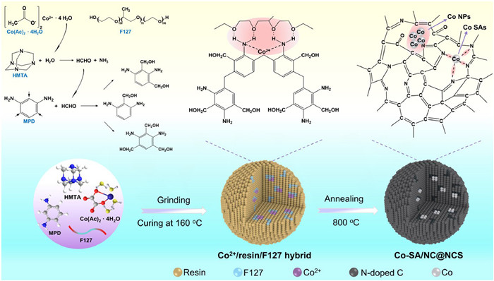
Schematic depiction for the solvent-free synthesis of Co2+/resin/F127 hybrid and Co-SA/NC@NCS.
Solvent-free synthesis of Co single atom and nanocluster decorated N-doped carbon for efficient oxygen reduction
Xinyuan Li , Zhuozhu Li , Wenzhong Huang , Jiantao Li , Wei Zhang , Shihao Feng , Hao Fan , Zhuo Chen , Sungsik Lee , Congcong Cai , Liang Zhou

Metal-air batteries have emerged as promising options for electrochemical energy storage. Especially, zinc-air batteries (ZABs) have garnered sustained attention owing to their high energy storage, low cost, and eco-friendliness [1-3]. However, the practical application of ZABs is impeded by the sluggish kinetics of oxygen reduction reaction (ORR) at the air electrode. The commercially employed Pt/C ORR catalyst suffers from high cost, poor stability, and sensitivity to methanol poisoning [4-6]. Consequently, it is imperative to develop alternative electrocatalysts featuring high activity, low cost, and enhanced stability.
Non-noble metal functionalized N-doped carbon has stood out as a substitute for Pt/C ORR catalyst, igniting extensive research efforts toward its synthesis [7-9]. Conventional solvent-based synthesis methods, including impregnation [10,11], hydrothermal [12,13], and solvothermal approaches [14,15], offer control over material composition and electron distribution. For example, single metal atom site decorated with metal nanoclusters has been synthesized using impregnation to regulate the electronic configuration, thereby enhancing ORR activity [10,11]. However, the solvent-based synthesis encounters challenges such as complex waste liquid treatment. In response, a series of solvent-free methods, including mechanochemical assembly [16,17], laser irradiation [18,19], and high-temperature solid diffusion [20-22], have been proposed. For example, Dai et al. reported a Ni/ordered mesoporous carbon catalyst through a mechanochemical assembly process involving polyphenol-metal complexes and triblock copolymers [16]. Yang et al. designed NiCo2O4 nanoparticles (NPs)/N-doped mesoporous carbon catalyst via laser irradiation to adjust the proportions of pyridinic-N and pyrrolic-N [18]. Li et al. reported a trifunctional self-standing Co/carbon nanotube film catalyst through an in situ solid diffusion strategy [20]. The aforementioned studies demonstrated the successful solvent-free synthesis of metal NPs/carbon catalysts. However, regulating the charge distribution of single atom sites by nanoclusters through solvent-free strategy has not yet been reported.
Herein, we propose a facile solvent-free organic-inorganic self-assembly strategy for the scalable preparation of cobalt single atom and cobalt nanocluster decorated nitrogen-doped porous carbon spheres (Co-SA/NC@NCS). The obtained Co-SA/NC@NCS possesses a Co loading amount of 0.90 wt% and a high nitrogen content of 6.9 wt%. It demonstrates excellent methanol tolerance, a favorable onset potential (Eonset) of 0.95 Ⅴ, and a half-wave potential (E1/2) of 0.82 Ⅴ. The eco-friendly solvent-free organic-inorganic self-assembly leads to an impressively high yield of 282 g/L and it is feasible for the preparation of other non-noble metal decorated nitrogen-doped carbon materials.
The solvent-free organic-inorganic self-assembly process is schematically shown in Fig. 1. First, m-phenylenediamine (MPD), hexamethylenetetramine (HMTA), triblock copolymers (F127), and cobalt acetate tetrahydrate ((CH3COO)2Co·4H2O) are ground in a mortar. Subsequently, the above blend is cured at 160 ℃, generating Co2+/resin/F127 hybrid. During the curing [23,24], the HMTA is decomposed into formaldehyde and ammonia with the participation of crystal water in (CH3COO)2Co·4H2O. The in-situ generated formaldehyde then polymerize with the MPD, generating MPD-formaldehyde resin [25]. The F127 and resin interact through hydrogen bonds [26], while the Co2+ is immobilized by the amino groups on the resin [27]. Lastly, the Co2+/resin/F127 hybrid is carbonized to obtain the Co-SA/NC@NCS. Solvent-free synthesis provides a high concentration of reactants, thereby enhancing the polymerization reaction in accordance with collision theory. The yields of Co2+/resin/F127 hybrid and Co-SA/NC@NCS reach 792 g/L and 282 g/L, respectively (Fig. S1 in Supporting information).
The Co2+/resin/F127 hybrid manifests a spherical geometry with a sleek surface, spanning sizes from 300 nm to 1200 nm (Fig. 2a). A small fraction of ellipsoids can also be observed (Fig. S2 in Supporting information). Throughout carbonization, the microspherical morphology can be well reserved (Figs. 2b and c, Fig. S3 in Supporting information). The cobalt species play a pivotal role in catalyzing the partial graphitization of carbon, as evidenced by the discontinuous graphitic layers with a spacing of ~0.37 nm at the edge of the microspheres (Fig. 2d). The partial graphitization of carbon is beneficial for enhancing the conductivity [28,29].

The amine-aldehyde condensation reaction endows abundant nitrogen species within the carbon framework, facilitating the anchoring of cobalt. Ultrafine Co nanoclusters are observed within the microsphere by high-resolution transmission electron microscope (HRTEM, Fig. 2e). The interlayer spacing of Co nanoclusters is measured to be 2.1 Å, aligning with the (111) crystal plane of metallic Co [30]. High-angle annular dark field scanning transmission electron microscopy (HAADF-STEM) manifests the existence of abundant Co single atoms (Fig. 2f). Energy-dispersive X-ray spectroscopy (EDS) elemental mappings confirm the even distribution of Co, C, N, and O in the Co-SA/NC@NCS (Fig. 2g). Without cobalt salt, the MPD and formaldehyde (released from the decomposition of HMTA) polymerize into microspheres with the assistance of structure directing agent F127, forming nitrogen-doped carbon spheres after carbonization. (Fig. S4 in Supporting information) [31].
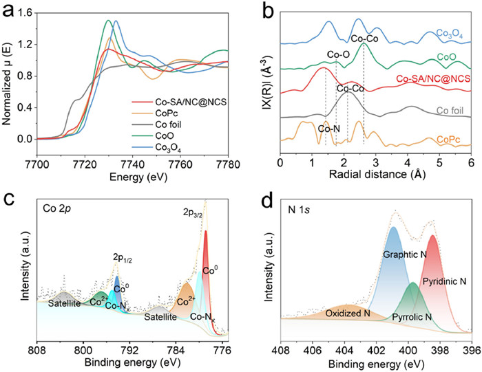
The local valence state and coordination environment for Co species are studied by X-ray absorption near-edge structure (XANES) and extended X-ray absorption fine structure (EXAFS) [32,33]. The Co K-edge XANES spectrum shows that the adsorption edge energy of Co-SA/NC@NCS is between those of the standard Co foil and CoO, indicating the co-existence of Co0 and Co2+ states (Fig. 3a). The Fourier-transformed EXAFS spectrum of Co-SA/NC@NCS presents a prominent peak at around 1.40 Å, which is close to the Co−N peak of CoPc (1.43 Å) and much shorter than the Co−O peak of CoO at 1.73 Å (Fig. 3b). This suggests the presence of Co−N bonds. In addition, the peak at 2.26 Å can be attributed to the Co−Co bonds, indicating the existence of Co NCs.
X-ray diffraction (XRD) patterns for both Co-SA/NC@NCS and NCS exhibit two broad peaks at 23.6° and 43.7°, corresponding to amorphous carbon (Fig. S5a in Supporting information). The small diffraction peak of Co-SA/NC@NCS at 44.6° corresponds to the (111) plane of Co (PDF #01–089–4307) [34], suggesting the presence of Co NCs. The Raman spectra of Co-SA/NC@NCS and NCS both display peaks at ~1342 cm−1 (D-band) and ~1587 cm−1 (G-band). The Co-SA/NC@NCS manifests a lower ID/IG (0.96 vs. 1.00) due to the partial graphitization of carbon (Fig. S5b in Supporting information) [35]. Nitrogen sorption is employed to assess the surface areas and pore size distributions. The introduction of triblock copolymer F127 affords NCS a high Brunauer-Emmett-Teller (BET) surface area of 633 m2/g (Fig. S6 in Supporting information). The Co-SA/NC@NCS exhibits a surface area of 432 m2/g.
The chemical composition of Co-SA/NC@NCS and the valance state of Co exert a significant influence on electrolyte wettability and electrocatalytic activity. X-ray photoelectron spectroscopy (XPS) survey spectrum reveals the existence of Co (0.7 wt%), N (6.9 wt%), O (4.6 wt%), and C (87.8 wt%) in Co-SA/NC@NCS (Fig. S7 in Supporting information). Inductively coupled plasma spectrometer (ICP) provides a Co content of 0.90 wt% [29], slightly exceeding the surface Co content determined from the XPS results. The high-resolution Co 2p spectrum of Co-SA/NC@NCS can be deconvoluted into eight components (Fig. 3c). The 2p3/2–2p1/2 spin-orbit doublet of Co0 is located at 778.8 and 794.2 eV, while the 2p3/2–2p1/2 spin-orbit doublet of Co2+ is situated at 782.2 and 796.9 eV. The peak at 779.9 and 795.1 eV are ascribed to CoNx moieties. The peaks at 786.7 and 803.7 eV are assigned to the satellite peaks [32,33,36]. The Co SAs accounts for 25.7% of the total Co species. The N 1s core level spectrum can be deconvoluted into four components at 398.5, 399.7, 400.9, and 403.8 eV, which are assigned to pyridinic-N, pyrrolic-N, graphitic-N, and pyridinic-N-O, respectively (Fig. 3d) [37]. Pyridinic-N and graphitic-N are identified as the predominant nitrogen species in Co-SA/NC@NCS, playing roles in fixing Co species and enhancing conductivity, respectively.
Benefiting from the solvent-free organic-inorganic self-assembly, the Co-SA/NC@NCS possesses a large surface area, high N content, and finely dispersed Co NCs and Co SAs, conferring decent ORR properties. Cyclic voltammetry (CV, Fig. S8 in Supporting information) curve of the Co-SA/NC@NCS collected at 5 mV/s shows a typical oxygen reduction peak at 0.85 Ⅴ (vs. reversible hydrogen electrode, RHE), which is higher than that of NCS (0.72 Ⅴ). Linear sweep voltammetry (LSV, Fig. 4a) curve of the Co-SA/NC@NCS displays a E1/2 of 0.82 Ⅴ, significantly higher than that of NCS (0.68 Ⅴ), Pt/C (20 wt%, 0.80 Ⅴ) and most Co-based electrocatalysts (Table S1 in Supporting information). Tafel plot (Fig. 4b) of the Co-SA/NC@NCS exhibits a smaller slope of 72 mV/dec than those of NCS (76 mV/dec) and Pt/C (95 mV/dec), demonstrating its fastest kinetics [38]. The limiting current density increases with rotating rates, accompanied by a stepwise decrease in diffusion distance (Fig. 4c). According to the Koutecky-Levich (K-L) plots, an average electron transfer number (n) of ~4 can be calculated (Fig. 4d). The LSV curve of Co-SA/NC@NCS exhibits only a slight degradation of the limiting current with the addition of methanol, indicating its ideal methanol tolerance (Fig. 4e). Long-term stability is another crucial performance metric for ORR. The Co-SA/NC@NCS demonstrates a current retention of 80.0% after 30,000 s (Fig. 4f), exceeding that of commercial Pt/C (59%).
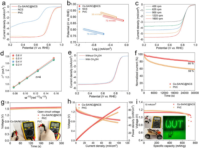
To assess the application potential of Co-SA/NC@NCS, the electrochemical performances of ZABs are evaluated. The Co-SA/NC@NCS demonstrates a higher open circuit voltage (1.58 Ⅴ) than that of the Pt/C-based battery (1.54 Ⅴ) (Fig. 4g). Discharge polarization and power density curves demonstrate a larger current density (102.8 mA/cm2) and power density (88.5 mW/cm2) for the Co-SA/NC@NCS based battery compared to the Pt/C-based one (98.1 mA/cm2, 74.0 mW/cm2) (Fig. 4h). Discharge curves (Fig. 4i) at 10 mA/cm2 reveal a specific discharge capacity (737.2 mAh/g) for the Co-SA/NC@NCS based battery, higher than the Pt/C-based one (697.7 mAh/g) after normalizing the consumed Zn plate. The rate performance of the zinc-air battery is evaluated (Fig. S9 in Supporting information). With the increasing of current density, the Zn-air batteries demonstrate a continuously decreasing but steady discharge voltage plateau. Upon reverting to 2 mA/cm2, the discharge voltage platform returns to its initial level. As shown in the digital photos (Fig. 4i inset), two Zn-air batteries (1.5 cm × 2 cm) in series are able to power 55 LEDs and a homemade toy car, and four Zn-air batteries in series exhibit a high OCV of 5.73 Ⅴ.
To elucidate the intrinsic active sites for ORR, SCN- is introduced to block the CoNx species. The introduction of SCN- causes a significant degradation of the ORR performance as shown in the LSV curve of Co-SA/NC@NCS (Fig. S10 in Supporting information), indicating the presence of CoNx. The impact of Co NCs is also evident from the deterioration of ORR performance after the removal of Co NCs from Co-SAs/NCs@NCS using 2.0 mol/L HCl at 70 ℃ for 12 h (Fig. S11 in Supporting information). Co-SA/NC@NCS subjected to annealing at 800 ℃ for 2 h (Co-SA/NC@NCS-800 ℃) exhibits degraded ORR performance (Fig. S12 in Supporting information), which may be attributed to the aggravation of Co species. Furthermore, the relationship between Co content and ORR performance is also explored (Fig. S13 in Supporting information). With a (CH3COO)2Co·4H2O amount of 0, 0.1, 0.2, 0.4, and 0.7 mmol introduced during the synthesis, the samples are designated as NCS, Co0.1@NCS, Co0.2@NCS, Co-SA/NC@NCS, and Co0.7@NCS, respectively. The NCS without Co species delivers a low limiting current density. With the introduction of 0.1 mmol Co salt, the Co0.1@NCS manifests a significantly improved ORR performance, but still exhibits a restricted limiting current. As the increases of introduced Co salt, the limiting current increases. Nevertheless, a significant weakening of the onset potential is observed when the amount of Co salt reaches 0.7 mmol, suggesting that a redundant of Co salt may hamper the dispersion of Co species. The Co-SA/NC@NCS demonstrates the highest onset potential and a considerably high limiting current density due to its appropriate Co content and finely dispersed Co NCs and SAs.
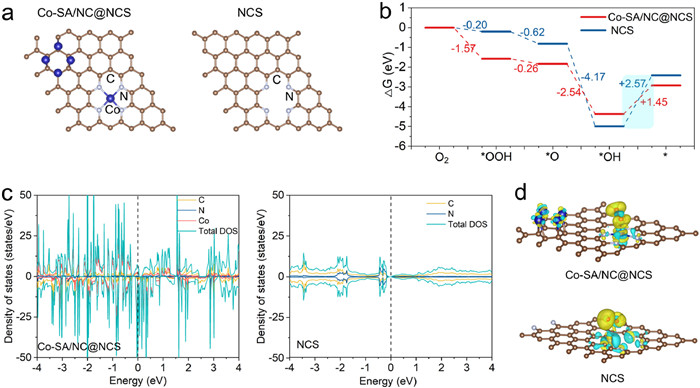
Density functional theory (DFT) calculations are employed to provide atomic-level insights into the ORR process [39]. Two structural models, Co-SA/NC@NCS and NCS, are established (Fig. 5a). In the NCS model, pyridinic nitrogen doping serves as the primary active site. In the Co-SA/NC@NCS model, both Co-SAs and Co NCs are anchored on nitrogen-doped carbon. DFT calculations are performed along the 4e- reaction pathway (O2* → OOH* → O* → OH* → *), and the free energies for different reaction intermediates are depicted (Fig. 5b, Fig. S14, Tables S2 and S3 in Supporting information). The negative overall Gibbs free energies (∆G) indicate the thermodynamic spontaneity of the ORR processes for both Co-SA/NC@NCS and NCS [40,41]. Compared to the NCS, the Co-SA/NC@NCS shows a more negative overall ∆G. In addition, the stronger adsorption towards OOH* suggests that the incorporation of Co SAs and Co NCs can modify the surface oxygen adsorption capability of NCS [10]. For both samples, step (iv) appears to be the rate-determining step, showing energy barriers of 1.45 and 2.57 eV for Co-SA/NC@NCS and NCS, respectively. To obtain information on the electron structure and potential reaction mechanism, density of states (DOS) calculations are conducted [32]. Compared to the NCS model, a narrower bandgap is observed for the Co-SA/NC@NCS, indicating its better electron conductivity (Fig. 5c). The electron accumulation between Co and O atoms suggests the strong O2 adsorption capability of Co SAs (Fig. 5d). Meanwhile, Co NCs and N sites also exhibit decent O2 adsorption capabilities. The above calculations indicate that Co-SA/NC@NCS can enhance the ORR activity by modifying the surface oxygen adsorption capability of NCS.
To demonstrate the versatility of the solvent-free organic-inorganic self-assembly, a series of non-noble metal elements (Fe, Ni, and Zn) have been successfully incorporated into the amine-formaldehyde resin-derived nitrogen-doped porous carbon spheres (e.g., Fe@NCS, Ni@NCS, and Zn@NCS) (Fig. S15 in Supporting information). Microscopy characterizations reveal that the Fe@NCS (Fig. S15a) and Ni@NCS (Fig. S15b) exhibit a regular microspherical morphology. The microspherical morphology of Zn@NCS is not as regular as those of Fe@NCS and Ni@NCS (Fig. S15c), which may be caused by the evaporation of Zn at high temperature. EDS elemental mappings (Figs. S15a4-c4) illustrate the even distribution of C, N, O, and introduced non-noble metal elements (Fe, Ni, Zn) in Fe@NCS, Ni@NCS, and Zn@NCS. The Co-SA/NC@NCS exhibits superior ORR activity relative to Fe@NCS, Ni@NCS, and Zn@NCS (Fig. S16), which can be attributed to the optimized electronic structure and unique active sites provided by Co SA and NC decoration.
In summary, a solvent-free organic-inorganic self-assembly strategy has been designed for the construction of Co single atom and nanocluster decorated nitrogen-doped porous carbon spheres (Co-SA/NC@NCS). The amine-aldehyde resin affords the products rich nitrogen species, which is favorable for anchoring the Co single atoms and nanoclusters. As an ORR catalyst, the Co-SA/NC@NCS manifests a high onset potential, a high limiting current, ideal methanol tolerance, and long-term stability. The solvent-free organic-inorganic self-assembly provides a versatile platform for the construction of transition metal species decorated nitrogen doped porous carbon composites with a notably high yield.
The authors declare that they have no known competing financial interests or personal relationships that could have appeared to influence the work reported in this paper.
Xinyuan Li: Writing – review & editing, Writing – original draft, Methodology, Investigation, Formal analysis. Zhuozhu Li: Writing – review & editing, Methodology. Wenzhong Huang: Writing – review & editing, Methodology. Jiantao Li: Writing – review & editing. Wei Zhang: Writing – review & editing, Writing – original draft. Shihao Feng: Writing – review & editing. Hao Fan: Writing – review & editing. Zhuo Chen: Writing – review & editing. Sungsik Lee: Methodology. Congcong Cai: Writing – review & editing. Liang Zhou: Writing – review & editing, Writing – original draft, Supervision, Methodology.
This work was supported by the National Natural Science Foundation of China (No. 52072283) and the program of China Scholarship Council (No. 202306950008). This research used resources of the Advanced Photon Source, a U.S. Department of Energy (DOE) Office of Science User Facility, operated for the DOE Office of Science by Argonne National Laboratory under Contract No. DE-AC02-06CH11357.
Supplementary material associated with this article can be found, in the online version, at doi:
W. Sun, F. Wang, B. Zhang, et al., Science 371 (2021) 46–51. doi: 10.1126/science.abb9554
L. Yang, C. Du, J. Tian, et al., Appl. Catal. B: Environ. 355 (2024) 124190. doi: 10.1016/j.apcatb.2024.124190
J. Tian, Y. Zhu, X. Yao, et al., J. Mater. Chem. A 11 (2023) 5288–5295. doi: 10.1039/d2ta08943b
M. Escudero-Escribano, P. Malacrida, M.H. Hansen, et al., Science 352 (2016) 73–76. doi: 10.1126/science.aad8892
X. Xie, Z. Zhai, L. Peng, et al., Sci. Bull. 68 (2023) 2862–2875. doi: 10.1016/j.scib.2023.10.013
C. Zhu, J. Yang, J. Zhang, et al., Interdiscip. Mater. 3 (2024) 74–86. doi: 10.1002/idm2.12141
V. Papa, Y. Cao, A. Spannenberg, et al., Nat. Catal. 3 (2020) 135–142. doi: 10.1038/s41929-019-0404-6
X. Yao, Y. Zhu, Z. Han, et al., Appl. Catal. B: Environ. 331 (2023) 122675. doi: 10.1016/j.apcatb.2023.122675
S. Xie, H. Jin, C. Wang, et al., Chin. Chem. Lett. 34 (2023) 107681. doi: 10.1016/j.cclet.2022.07.024
F. Yu, J. Zhan, D. Chen, et al., Adv. Funct. Mater. 33 (2023) 2214425. doi: 10.1002/adfm.202214425
H. Liu, L. Jiang, J. Khan, et al., Angew. Chem. Int. Ed. 62 (2023) e202214988. doi: 10.1002/anie.202214988
J. Song, Y. Chen, H. Huang, et al., Adv. Sci. 9 (2022) 2104522. doi: 10.1002/advs.202104522
S. Zhao, F. Hu, L. Yin, et al., Sci. Bull. 68 (2023) 1389–1398. doi: 10.1016/j.scib.2023.06.001
B. Ramulu, S.J. Arbaz, M. Nagaraju, et al., Nanoscale 15 (2023) 13049–13061. doi: 10.1039/d3nr02103c
M. Song, Q. Zhang, T. Shen, et al., Chin. Chem. Lett. 35 (2024) 109083. doi: 10.1016/j.cclet.2023.109083
P. Zhang, L. Wang, S. Yang, et al., Nat. Commun. 8 (2017) 15020. doi: 10.1038/ncomms15020
S. Li, G. Xing, S. Zhao, et al., Nat. Sci. Rev. 11 (2024) nwae193. doi: 10.1093/nsr/nwae193
X.R. Wang, J.Y. Liu, Z.W. Liu, et al., Adv. Mater. 30 (2018) 1800005. doi: 10.1002/adma.201800005
Z. Wang, Q.K. Li, C. Zhang, et al., ACS Catal. 11 (2021) 2454–2459. doi: 10.1021/acscatal.0c04735
Z. Yang, C. Zhao, Y. Qu, et al., Adv. Mater. 31 (2019) 1808043. doi: 10.1002/adma.201808043
S. Liu, M. Wang, X. Yang, et al., Angew. Chem. Int. Ed. 59 (2020) 21698–21705. doi: 10.1002/anie.202009331
Z. Zhuang, Y. Li, R. Yu, et al., Nat. Catal. 5 (2022) 300–310. doi: 10.1038/s41929-022-00764-9
F. Liu, K. Huang, Q. Wu, et al., Adv. Mater. 29 (2017) 1700445. doi: 10.1002/adma.201700445
S. Feng, K. Li, P. Hu, et al., ACS Nano 17 (2023) 23152–23159. doi: 10.1021/acsnano.3c09328
R. Chen, X. Li, C. Cai, et al., Small 19 (2023) 2303790. doi: 10.1002/smll.202303790
T. Wang, F. Okejiri, Z.A. Qiao, et al., Adv. Mater. 32 (2020) 2002475. doi: 10.1002/adma.202002475
S. Jin, Y. Ni, Z. Hao, et al., Angew. Chem. Int. Ed. 59 (2020) 21885–21889. doi: 10.1002/anie.202008422
Z. Wang, C. Zhu, H. Tan, et al., Adv. Funct. Mater. 31 (2021) 2104735. doi: 10.1002/adfm.202104735
J. Meng, J. Li, J. Liu, et al., ACS Cent. Sci. 6 (2020) 1431–1440. doi: 10.1021/acscentsci.0c00458
J. Yan, Y. Wang, Y. Zhang, et al., Adv. Mater. 33 (2020) 2007525.
S. Feng, L. Xing, K. Li, et al., Small Methods 7 (2023) 2300150. doi: 10.1002/smtd.202300150
L. Wang, Y. Hao, L. Deng, et al., Nat. Commun. 13 (2022) 5785. doi: 10.1177/09544062211063130
Y. Hao, S. Hung, W. Zeng, et al., J. Am. Chem. Soc. 145 (2023) 23659–23669. doi: 10.1021/jacs.3c07777
K.E. Fritz, Y. Yan, J. Suntivich, et al., Nano Res. 12 (2019) 2307–2312. doi: 10.1007/s12274-019-2440-6
X. Li, Z. Liu, C. Cai, et al., ChemSusChem 14 (2021) 1756–1762. doi: 10.1002/cssc.202100113
X. Jia, Y. Zhang, D. Guo, et al., Ionics 26 (2020) 1885–1894 (Kiel). doi: 10.1007/s11581-020-03465-0
X. Li, C. Cai, P. Hu, et al., Adv. Mater. 36 (2024) 2400184. doi: 10.1002/adma.202400184
Y. Ren, F. Tian, L. Jin, et al., Environ. Sci. Technol. 57 (2023) 10458–10466. doi: 10.1021/acs.est.3c02520
L. Jin, X. Duan, M. Sun, et al., ACS Nano 17 (2023) 12875–12883. doi: 10.1021/acsnano.3c04521
Y. Wang, Y.J. Tang, K. Zhou, et al., J. Am. Chem. Soc. 141 (2019) 14115–14119. doi: 10.1021/jacs.9b07712
W. Wang, X. Deng, Z. Tian, et al., Chem. Mater. 35 (2023) 6070–6082. doi: 10.1021/acs.chemmater.3c01171

Figure 1 Schematic depiction for the solvent-free synthesis of Co2+/resin/F127 hybrid and Co-SA/NC@NCS.

Figure 2 Microscopy characterizations of the Co2+/resin/F127 hybrid and Co-SA/NC@NCS. Scanning electron microscopy (SEM) images of Co2+/resin/F127 (a) and Co-SA/NC@NCS (b, c). (d, e) HRTEM images of Co-SA/NC@NCS. (f) HAADF-STEM image of Co-SA/NC@NCS. (g) HAADF-STEM image and the corresponding EDS elemental mappings of Co-SA/NC@NCS.

Figure 3 Structural characterizations of the as-prepared catalysts. (a) Co K-edge XANES spectra and (b) Fourier-transform EXAFS spectra of Co-SA/NC@NCS, CoPc, Co foil, CoO, and Co3O4. (c, d) High-resolution Co 2p and N 1s XPS spectra of Co-SA/NC@NCS.

Figure 4 ORR performance. (a) LSV curves of Co-SA/NC@NCS, NCS, and Pt/C in O2-saturated 0.1 mol/L KOH (1600 rpm at 5 mV/s). (b) Tafel plots derived from (a). (c) LSV curves of Co-SA/NC@NCS at rotating rates from 400 rpm to 1600 rpm. (d) K-L plots derived from (c). (e) LSV curves of Co-SA/NC@NCS with and without the introduction of CH3OH. (f) Stability tests of Co-SA/NC@NCS and Pt/C. Performance comparison of Zn-air batteries using Co-SA/NC@NCS and Pt/C catalysts: (g) OCV stability (inset: digital photos indicating the OCV). (h) Discharge polarization and corresponding power density curves. (i) Discharge curves at 10 mA/cm2. Inset: digital photo showing the OCV of 4 solid Zn-air batteries in series, and the toy car and 55 LEDs powered by 2 solid Zn-air batteries in series.

 扫一扫看文章

扫一扫关注我们
 DownLoad:
 下载:
下载:

 下载:
下载: