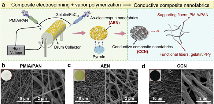
Figure 1.
(a) Fabrication process of the conductive composite nanofabrics (CCN). SEM images and the corresponding digital photos of the prepared (b) PMIA/PAN nanofabrics, (c) as-electrospun nanofabrics (AEN) and (d) CCN samples.
Conductive nanofabrics as multifunctional interlayer of sulfur-loading cathode towards durable lithium-sulfur batteries
Min Chen , Xinxin Li , Weijie Cai , Xinxin Han , Chuancong Zhou , Ke Zheng , Ruomeng Duan , Yanfei Zhao , Mengmeng Shao , Wenlong Wang , Kaihong Zheng , Bo Feng , Xiaodong Shi

Lithium-sulfur batteries (LSBs) have attracted great attention as a promising candidate for next-generation energy storage devices owing to the advantages of high theoretical capacity and high energy density. However, the commercialization of LSBs is still hindered by the serious shuttle behavior of lithium polysulfides (LiPSs, Li2Sx, 2 < x ≤ 8), which is the intermediates during discharge process of sulfur-loading cathode, and easily dissolved in the electrolyte, leading to the low utilization rate of active sulfur, rapid capacity decay and short service life. Additionally, the LiPSs shuttling through the separator also tend to react with lithium anode and induce severe metal corrosion.
To well deal with the shuttle effect of LiPSs, a series of sulfur host materials were widely proposed to realize effective confinement of active sulfur component, such as porous carbon materials [1–4], and metal nanoparticles/carbon composites [5–8], and metal-based compounds/carbon composites [9–11]. Meanwhile, a series of functional binders, such as synthetic polymers [12–14], proteins [15,16], and saccharides [17,18], were also reported to restrict the shuttle behavior of LiPSs through their strong chemisorption capability for LiPSs. Currently, separator engineering, including coating layer on the surface of separator and interlayer within sulfur-loading cathode and separator, was demonstrated as alternative approaches to address the above issues through the strong chemical interactions with LiPSs, which can not only anchor the LiPSs but also facilitate the conversion reaction from LiPSs to Li2S2/Li2S [19–22]. As an interlayer within the sulfur-loading cathode and separator, it is an urgent requirement to fabricate self-supporting films with stable skeleton structure, high electrical conductivity and abundant active groups [23–25]. Guo et al. prepared a freestanding Co3O4/CNFs composite membrane though hydrothermal method [26], in which the intertwined CNFs was recognized as conductive support to guarantee the fast transportation behavior of Li+ ions and electrons, and the Co3O4 component provided active sites for the chemisorption and catalytic conversion of LiPSs.
Comparatively, electrospinning technique is considered as a facile and practical method to realize the customized preparation of free-standing membrane [27,28], which can be effectively decorated with polar materials to enhance the interactions with LiPSs. For instance, Fe single atoms-doped porous carbon was served as interlayer for LSBs [29], and the corresponding coulombic efficiency could maintain at 99% within 400 cycles and 95% after 1600 cycles at high current density of 3 C. Unfortunately, the fabrication procedure of carbon-based conductive interlayers is always complicate, laborious, and multi-step, containing at least the process of electrospinning, high-temperature calcination, and active component decoration, which is not conducive to practical application. Considering the positive role of conductive polymers as functional coating material of separator for LSBs [30,31], it is a well-worthy trying but still challenging to simultaneously realize the efficient construction of robust skeleton, conductive polymer and functional groups through one-step electrospinning strategy.
In this work, conductive composite nanofabrics (CCN) are successfully prepared with poly(m-phenylenedicarboxamide)/polyacrylonitrile (PMIA/PAN) composite as the supporting fibers and gelatin/polypyrrole (PPy) composite as the functional fibers via composite electrospinning and a followed vapor-phase polymerization. As the interlayer for sulfur-loading cathode of LSBs, the supporting fibers endow CCN with high mechanical strength and high heat-endurance, and the functional fibers provide CNN with high conductivity and strong chemisorption capability for LiPSs. Specifically, gelatin shows chemical interactions with polysulfides due to its rich polar groups thus can be applied as a polysulfide absorbent to inhibit shuttle effect in LSBs [32,33]. Polypyrrole is a conductive polymer which endows the designed interlayer with high electrical conductivity, with which the interlayer can not only trap polysulfides but also convert them into Li2S2/L2S, contributing to higher capacity. A conductive interlayer can also promote charge transfer and enhance the rate performance of the batteries [34]. As disclosed by the experimental results, the introduction of CCN interlayer effectively inhibits the shuttle effect of LiPSs and promotes the interface stability of lithium anode. Consequently, with the presence of CCN interlayer, the assembled LSBs can exhibit high reversible capacity of 686 mAh/g after 200 cycles at 0.5 A/g, indicating durable cycling performance and high utilization rate of active sulfur.
To design a robust conductive interlayer with satisfactory LiPSs-trapping capability, a new type of nanofabrics composed by PMIA/PAN supporting fibers and gelatin/polypyrrole functional fibers is fabricated by composite electrospinning technology and a followed vapor-phase polymerization (Fig. 1a). Especially, PMIA component holds superior mechanical strength, electrochemical stability, thermal stability and self-extinguishing performance, while its spinnability and production efficiency can be boosted by the introduction of PAN component (Fig. S1 in Supporting information) [35,36]. As the functional component in the composite nanofabrics, gelatin/polypyrrole fibers can anchor the LiPSs by gelatin, and convert the trapped LiPSs with the assistance of conductive polypyrrole, which is mainly derived from the chemical reaction between gelatin/FeCl3 fibers and pyrrole vapor. It should be noted that PMIA/PAN is dissolved in an organic solvent of dimethylacetamide (DMAc), while gelatin/FeCl3 is dissolved in an acetic acid aqueous solution when electrospinning. Compared with common blend electrospinning that requires all the component dissolving in one same solvent, composite electrospinning contains two sets of solution supply system thus components with different solubilities could be dissolved separately for electrospinning, which provides high flexibility in material component design. As observed, the optimized PMIA/PAN nanofabrics is a white membrane with fibrous structure and the fibers are uniformly distributed to form a favorable pore structure for fast ion transport (Fig. 1b). The as-electrospun nanofabrics (AEN), composed by PMIA/PAN and gelatin/FeCl3 component, is yellow-colored and the composite fibers pile up more firmly in comparison with PMIA/PAN nanofabrics (Fig. 1c). After polymerization, the yellow AEN membrane turns black owing to the formation of polypyrrole (Fig. 1d), which is completely coated on the surface of composite fibers to realize the fabrication of conductive composite nanofabrics (CCN).
To verify the occurrence of polymerization reaction, the FTIR spectra of PMIA/PAN, AEN and CCN membrane were collected. For the PMIA/PAN nanofabrics, the absorption peaks located at 1654 cm-1 and 1541 cm-1 are ascribed to the C—O and N—H stretching vibration of PMIA [37]. For the AEN membrane, its FTIR spectra is similar to that of PMIA/PAN nanofabrics. The characteristic active group (-CONH-) of gelatin around 1654 and 1541 cm-1 overlaps with the functional groups of PMIA, while the broad peak at 3302 cm-1 may be enhanced by the introduction of -OH from gelatin (Fig. 2a). For the CCN membrane, the obvious peak at 1534 cm-1 well corresponds to the ring stretching vibration of C═C bond, and the appearances of 1292 cm-1 (C—H and C—N in-plane deformation), 1162 cm-1 (C—N stretching vibrations of pyrrole ring) and 1034 cm-1 (C—H deformation and N—H vibrations) further manifest the attendance of polypyrrole [38]. Along with the vapor-phase polymerization process, the electrical conductivity of CNN increases with the reaction time (Fig. 2b). In detail, the corresponding electrical conductivity of CCN reaches 1.56 S/m after 36 h and remains nearly unchanged for 48 h or even 60 h The FeCl3 contained in the AEN induces the vapor-phase polymerization of pyrrole monomers to generate polypyrrole. With longer reaction time, more polypyrrole formed on the gelatin/ FeCl3 fibers. Once polypyrrole particles connect with each other to form a film, a consecutive conductive pathway is established, and the electrical conductivity increases sharply. After then, more polypyrrole generated only leads to thicker conductive pathway and the electrical conductivity does not change dramatically.
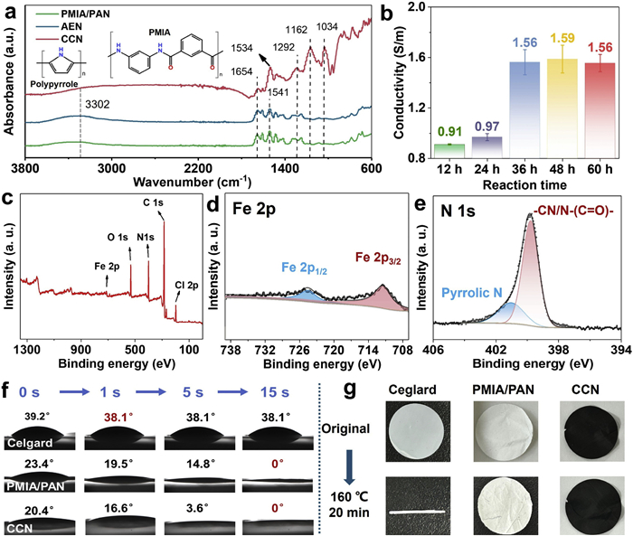
The surface chemical composition of CCN was further investigated by X-ray photoelectron spectroscopy (XPS). As summarized in Fig. 2c, the peaks at 198.7, 285.2, 400.1, 532.0 and 711.9 eV in the survey spectra correspond to the Cl 2p, C 1s, N 1s, O 1s and Fe 2p spectra, respectively. For the high-resolution Fe 2p spectra (Fig. 2d), it can be divided into two representative peaks centered at 711.4 eV (Fe 2p3/2) and 724.5 eV (Fe 2p1/2), respectively. For the high-resolution N 1s spectra (Fig. 2e), the deconvoluted N 1s peak suggests the existence of -CN/N-(C═O)- (399.8 eV) and pyrrolic N (401.0 eV), respectively, originating from the components of CCN, namely gelatin, PMIA, PAN and polypyrrole. Additionally, the high-resolution C 1s/O 1s spectra (Fig. S2 in Supporting information) and the EDS mapping analysis of CCN (Fig. S3 in Supporting information) also confirm the presence of N-containing and Fe-containing species. Fig. 2f records the dynamic contact angles of liquid electrolyte on the surface of different membranes. The CCN membrane delivers smaller contact angles than those of Celgard and PMIA/PAN throughout the interfacial wetting process, demonstrating its superior wettability and hydrophilicity brought by gelatin and polypyrrole, which is conducive to reducing the interface impedance. Fig. S4 (Supporting information) evaluates the mechanical property of Celgard and PMIA/PAN membranes, and the average tensile strength of PMIA/PAN nanofabrics is 21.7 MPa, much higher than that of Celgard (11 MPa), indicating the inherent high mechanical strength of PMIA/PAN-based membranes. The thermal stability of Celgard, PMIA/PAN and CCN membranes were tested by heating treatment at 160 ℃ for 20 min. As a result, the surface morphology of CCN and PMIA/PAN fibers is almost unchanged only with the formation of small local folds (Fig. 2g, Figs. S5 and S6 in Supporting information), exhibiting outstanding thermostability, which can be ascribed to the intrinsic thermal stability and flame-retardant property of PMIA component. In sharp contrast, the surface of Celgard separator suffers from dramatical shrinkage, implying its inferior thermostability, which may induce the battery short circuit and greatly reduce the battery safety.
Electrochemical impedance spectroscopy (EIS) tests of LSBs were conducted to investigate the influences of CCN interlayer on the interface charge transfer behavior. Based on the equivalent circuit models, the semicircle at high-to-medium frequency corresponds to the charge transfer resistance (Rct) for the fresh LSBs [39], while the second incomplete semicircle at low frequency is ascribed to the interface impedance related to the formation of solid electrolyte interface (SEI) film (RSEI) for the cycled LSBs [40,41]. Briefly, the Rct of cell without CCN interlayer decreases from 215 Ω to 31.9 Ω after cycles, and both of them are higher than that of cell with CCN interlayer (from 70.6 Ω to 18.3 Ω), suggesting the introduction of CCN effectively reduces the charge transfer resistance (Figs. 3a and b). Additionally, the second semicircle for the LSBs with CCN interlayer is negligible, implying that CCN layer holds strong LiPSs-trapping capability to inhibit the diffusion of soluble LiPSs from sulfur-containing cathode to Li anode, as well as the formation of Li2S/Li2S2 film. The above results indicate that the CCN can enhance the reaction kinetics and block the shuttling of LiPSs. To be noted that the charge transfer resistances of both cells sharply decrease after cycles, which is related to the dissolution and redistribution of active materials during the activation process [42,43]. As presented in Figs. 3c and d, the cyclic voltammetry (CV) curves of cells with/without CCN interlayer were measured within a voltage range of 1.8–2.8 V at 0.1 mV/s. Notably, there are two cathodic peaks around 2.3 and 2.0 V, respectively corresponding to the reduction of S8 to soluble LiPSs with long chains (Li2Sx, 4 ≤ x ≤ 8) and the further conversion from soluble LiPSs to insoluble Li2S2/Li2S. The anodic peak around 2.4 V can be attributed to the opposite reaction process to the cathodic peaks. As compared in Fig. S7 (Supporting information), the CV curves of cell with CCN interlayer deliver positive shift of cathodic peaks and negative shift of anodic peaks, demonstrating its smaller voltage polarization (0.1 V vs. 0.17 V) and faster redox reaction kinetics. Additionally, the CV curves of cell with CCN interlayer exhibit larger enclosed region, higher peak currents and higher consistency, implying higher utilization rate of active sulfur owing to the strong interaction between CCN layer and LiPSs. Furthermore, CV tests at different scan rates were performed to explore the Li-ion diffusion properties of the CCN interlayer (Fig. S8 in Supporting information). The peak current and polarization increase with the scan rate and a linear relationship between the peak currents and square root of scan rates can be seen, suggesting the diffusion-controlled reaction mechanism of the Li2S4/S8 redox pair [44,45].
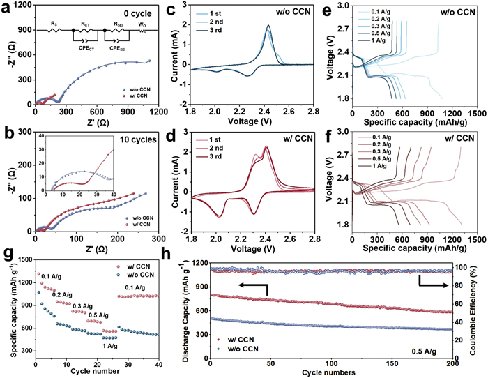
Figs. 3e and f compare the galvanostatic charge-discharge curves of LSBs with/without CCN interlayer at different current densities. The cell with CCN interlayer delivers long and flat charge-discharge plateaus, especially the one at ~2.1 V corresponding to the conversion of Li2S4 → Li2S2, reflecting the high electrical conductivity and low internal resistance brought by CCN. To disclose the positive effects of CCN interlayer on the electrochemical performances, rate performance and cycle stability of cells with/without CCN were further investigated. In details, with the introduction of CCN interlayer, the reversible discharge capacities of cell are 1163, 936, 816, 691, and 562 mAh/g at the current density of 0.1, 0.2, 0.3, 0.5 and 1 A/g, respectively (Fig. 3g). In comparison, the corresponding cell without CCN interlayer only display lower discharge capacity of 872, 644, 576, 528 and 474 mAh/g at 0.1, 0.2, 0.3, 0.5 and 1 A/g, respectively. When the current density returns to 0.1 A/g, the average capacity of CCN cell recovers to 1022 mAh/g with a retention of 87.9% while that of cell without CCN only display a capacity of 581 mAh/g with a retention of 62.9%. Moreover, the cell with CCN interlayer exhibit higher capacity throughout the 200 cycles at a current density of 0.5 A/g, corresponding to an average discharge capacity of 686 mAh/g (Fig. 3h), much higher than that without CCN interlayer (417 mAh/g). Both the outstanding rate performance and cycle stability are benefitted from the strong LiPSs-trapping capability of gelatin and polypyrrole components in CCN interlayer, which can reduce the loss of active sulfur species and inhibit the shuttle effect of LiPSs. To investigate the interaction effect between CCN interlayer and LiPSs, the XPS spectra of CCN interlayer after cycles were detected. Based on the survey XPS and high-resolution C 1s/O 1s spectra, a new peak belonging to C-F bond appears at 293.1 eV, originating from the TFSI- ions in liquid electrolyte (Figs. S9a and b in Supporting information), while the C—O peak overlaps with S-O (SOx) peak at 533.1 eV (Fig. S9c in Supporting information), indicating the residue of sulfur species on the CCN interlayer, which can be further confirmed by the peak splitting results of high-resolution S 2p spectra (Fig. S9d in Supporting information). It is worth mentioning that the main peaks at 169.5/170.7 eV and 167.5/168.7 eV are well assigned to the compound of polythionate and thiosulfate coming from the oxidation reaction of LiPSs [24]. Additionally, the surface morphology (Fig. S10 in Supporting information) and EDS mapping analysis (Fig. S11 in Supporting information) also testify the existence of S-containing species in the cycled CCN interlayer, demonstrating its effective adsorption capability on the LiPSs.
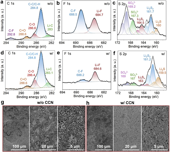
The positive roles of CCN interlayer for the formation of solid electrolyte interface (SEI) film and the corrosion of LiPSs on the surface of lithium metal anode were characterized by the XPS techniques. Fig. S12 (Supporting information) and Figs. 4a-c comprehensively present the survey XPS spectra, high-resolution C 1s, O 1s, F 1s and S 2p spectra of lithium metal disassembled from the cycled LSBs without CCN interlayer. Notably, a distinct peak at 292.8 eV in C 1s spectra corresponds to C-F bond (Fig. 4a), which can be attributed to the decomposition of LiTFSI component in liquid electrolyte [46]. For the F 1s spectra, two characteristic peaks at 688.5 and 684.7 eV are respectively assigned to the C-F and Li-F bonds (Fig. 4b), and the larger region proportion of C-F bond manifests the dominant position of organic species in the SEI composition. For the S 2p spectra, the evident peaks at higher binding energy of 169.2 and 167.3 eV, can be identified as SO42- and SO32-, originating from the complete decomposition of LiTFSI component in the presence of LiNO3 additive [47]. Meanwhile, three typical peaks at lower binding energy of 164.5, 161.7 and 160 eV respectively match with the functional groups of Li2Sx (2 < x ≤ 8), Li2S2 and Li2S (Fig. 4c). The existence of Li2Sx can be ascribed to the severe shuttle behavior of LiPSs from sulfur-loading cathode to lithium metal anode [48,49], while the attendance of Li2S2 and Li2S may be mainly derived from the surface chemical reaction between lithium metal and LiTFSI component in liquid electrolyte [50]. After carefully checking the high-resolution C 1s, F 1s and S 2p spectra of lithium metal disassembled from the cycled LSBs with CCN interlayer (Figs. 4d-f), some differences are summarized as follows: (1) Inorganic species (Li-F bond) become the main component of SEI on the surface of lithium metal (Figs. 4d and e), which effectively facilitates the transport behavior and uniform deposition of Li+ ions to resist the formation of lithium dendrites [51]; (2) The region proportion of Li2Sx is greatly reduced (Fig. 4f), implying the effective inhibition of LiPSs shuttle behavior with the introduction of CCN interlayer. Additionally, the surface morphology of lithium metal harvested from the cycled LSBs were also investigated to testify the positive effect of CCN interlayer on the inhibition of lithium dendrites. Without the presence of CNN interlayer, the obtained lithium metal has a rough and loose surface with massive vertically growing Li plates (Fig. 4g), which always leads to unstable interface reaction and continuous consumption of electrolyte during cycling process [52]. In sharp comparison, the corresponding lithium metal with CCN as the interlayer presents a clear, smooth and compact surface without apparent lithium dendrites (Fig. 4h) owing to the stable SEI film and high reversibility of lithium stripping/plating behavior, demonstrating that the introduction of CCN interlayer not only effectively inhibits the LiPSs shuttle effect of sulfur-loading cathode to promote the active sulfur utilization and cyclic stability, but also significantly reduces the side reactions on the surface of Li anode to strengthen the interface stability and battery safety.
In summary, an electrospun CNN interlayer is well-designed for the sulfur-loading cathode of LSBs with PMIA/PAN composite as the supporting fibers and gelatin/PPy composite as the functional fibers. In details, the supporting fibers can guarantee robust skeleton structure, high mechanical property and high thermostability, while the functional fibers can endow the CNN interlayer with high electrical conductivity and strong chemisorption capability as well as unique chemical interaction for LiPSs. The interfacial resistance could also be reduced by the improved wettability, high porosity and electrical conductivity. The experiment results manifest the presence of CCN interlayer effectively blocks the shuttle behavior of LiPSs from sulfur-loading cathode and induces the formation of favorable SEI film with dominant inorganic species on the surface of lithium metal anode, contributing to the low active sulfur loss, high specific capacity and stable cycling performance of LSBs. As expected, the optimized sulfur-loading cathode with CCN interlayer delivers high reversible capacity of 686 mAh/g after 200 cycles at 0.5 A/g, suggesting superior cycling stability and rate capability. This study proposes a versatile strategy for the custom fabrication of multifunctional separators or interlayers for advanced secondary batteries, which can simultaneously stabilize the electrode/electrolyte interfaces of both active cathode and metal anode.
The authors declare that they have no known competing financial interests or personal relationships that could have appeared to influence the work reported in this paper.
Min Chen: Investigation, Funding acquisition, Conceptualization. Xinxin Li: Investigation, Data curation. Weijie Cai: Resources, Formal analysis. Xinxin Han: Validation. Chuancong Zhou: Validation, Software. Ke Zheng: Resources, Methodology. Ruomeng Duan: Validation, Resources. Yanfei Zhao: Visualization, Data curation. Mengmeng Shao: Investigation, Formal analysis. Wenlong Wang: Visualization, Validation. Kaihong Zheng: Writing – review & editing, Methodology. Bo Feng: Writing – original draft, Project administration, Conceptualization. Xiaodong Shi: Writing – review & editing, Writing – original draft, Supervision, Project administration, Funding acquisition.
This work was supported by National Natural Science Foundation of China (No. 22309029), Guangdong Basic and Applied Basic Research Foundation (No. 2021A1515110089), Dongguan Social Development Technology Foundation (No. 20231800907933), Collaborative Innovation Center of Marine Science and Technology of Hainan University (No. XTCX2022HYC14), and Start-up Research Foundation of Hainan University (No. KYQD(ZR)-23069). Additionally, the authors acknowledge the supports of comprehensive characterizations by Dongguan University of Technology Analytical and Testing Center, Pico Election Microscopy Center of Hainan University and Shiyanjia lab (
Supplementary material associated with this article can be found, in the online version, at doi:
M. Zhao, Y.Q. Peng, B.Q. Li, et al., J. Energy Chem. 56 (2021) 203–208. doi: 10.1016/j.jechem.2020.07.054
P. Yu, L.X. Feng, D.C. Ma, et al., Adv. Funct. Mater. 31 (2021) 2008652. doi: 10.1002/adfm.202008652
Y. Tsao, H. Gong, S. Chen, et al., Adv. Energy Mater. 11 (2021) 2101449. doi: 10.1002/aenm.202101449
P. Wang, X. Dai, P. Xu, et al., eScience 3 (2023) 100088. doi: 10.1016/j.esci.2022.100088
Y. Xie, J. Ao, L. Zhang, Y. Shao, et al., Chem. Eng. J. 451 (2023) 139017. doi: 10.1016/j.cej.2022.139017
L. Feng, R. Yan, X.R. Sun, et al., Adv. Energy Mater. 14 (2024) 2303848. doi: 10.1002/aenm.202303848
Y. Zhang, Y. Qiu, L. Fan, et al., Energy Stor. Mater. 63 (2023) 103026.
C. Zhao, B. Jiang, Y. Huang, et al., Energy Environ. Sci. 16 (2023) 5490–5499. doi: 10.1039/d3ee01774e
H. Zhang, L.K. Ono, G. Tong, et al., Nat. Commun. 12 (2021) 4738. doi: 10.1038/s41467-021-24976-y
Y. Yao, H. Wang, H. Yang, et al., Adv. Mater. 32 (2020) 1905658. doi: 10.1002/adma.201905658
B. Guan, X. Sun, Y. Zhang, X. Wu, et al., Chin. Chem. Lett. 32 (2021) 2249–2253. doi: 10.1016/j.cclet.2020.12.051
D. Chen, M. Song, M. Zhu, et al., ACS Appl. Energy Mater. 5 (2022) 5287–5295. doi: 10.1021/acsaem.2c00817
X. He, Z. Liu, G. Gao, et al., J. Energy Chem. 59 (2021) 1–8. doi: 10.1016/j.jechem.2020.10.002
Z. Liu, X. He, C. Fang, et al., Adv. Funct. Mater. 30 (2020) 2003605. doi: 10.1002/adfm.202003605
R. Sun, J. Hu, X. Shi, et al., Adv. Funct. Mater. 31 (2021) 2104858. doi: 10.1002/adfm.202104858
X. Fu, L. Scudiero, W.H. Zhong, J. Mater. Chem. A 7 (2019) 1835–1848. doi: 10.1039/c8ta11384j
Y. Huang, M. Shaibani, T.D. Gamot, et al., Nat. Commun. 12 (2021) 5375. doi: 10.1038/s41467-021-25612-5
J. Liu, D.G.D. Galpaya, L. Yan, et al., Energy Environ. Sci. 10 (2017) 750–755. doi: 10.1039/C6EE03033E
H. Li, W. Zheng, H. Wu, et al., Small 20 (2024) 2306140. doi: 10.1002/smll.202306140
S. Wang, X. Liu, H. Duan, et al., Chem. Eng. J. 415 (2021) 129001. doi: 10.1016/j.cej.2021.129001
S. Tu, X. Chen, X. Zhao, et al., Adv. Mater. 30 (2018) 1804581. doi: 10.1002/adma.201804581
F.-L. Zeng, F. Wang, N. Li, et al., Nanoscale 13 (2021) 17592–17602. doi: 10.1039/d1nr04357a
J. Zhao, Y. Zhao, W.C. Yue, et al., Chem. Eng. J. 441 (2022) 136082. doi: 10.1016/j.cej.2022.136082
X. Dai, G. Lv, Z. Wu, et al., Adv. Energy Mater. 13 (2023) 2300452. doi: 10.1002/aenm.202300452
Y.C. Jeong, J.H. Kim, S. Nam, et al., Adv. Funct. Mater. 28 (2018) 1707411. doi: 10.1002/adfm.201707411
J. Guo, H. Jiang, M. Yu, et al., Chem. Eng. J. 449 (2022) 137777. doi: 10.1016/j.cej.2022.137777
S. Wu, X. Nie, Z. Wang, et al., Carbon 201 (2023) 285–294. doi: 10.3390/drones7050285
B. Song, H. Zhao, G. Zhao, et al., Chem. Eng. J. 460 (2023) 141907. doi: 10.1016/j.cej.2023.141907
J. Yang, D.W. Kang, H. Kim, et al., Chem. Eng. J. 451 (2023) 138909. doi: 10.1016/j.cej.2022.138909
D. Guo, X. Li, F. Ming, et al., Nano Energy 73 (2020) 104769. doi: 10.1016/j.nanoen.2020.104769
Y. Li, W. Wang, X. Liu, et al., Energy Stor. Mater. 23 (2019) 261–268. doi: 10.3390/molecules24020261
M. Chen, X. Fu, N.D. Taylor, et al., ACS Sustain. Chem. Eng. 7 (2019) 15267–15277. doi: 10.1021/acssuschemeng.9b02383
M. Chen, C. Li, X. Fu, et al., Adv. Energy Mater. 10 (2020) 1903642. doi: 10.1002/aenm.201903642
X. Wu, N. Liu, Z. Guo, et al., Energy Stor. Mater. 28 (2020) 153–159.
N. Deng, L. Wang, Y. Feng, et al., Chem. Eng. J. 388 (2020) 124241. doi: 10.1016/j.cej.2020.124241
A. Rianjanu, K.D.P. Marpaung, E.K.A. Melati, et al., Nano Mater. Sci. 6 (2024) 96–105. doi: 10.1016/j.nanoms.2023.10.006
Q. Geng, Y. Pu, Y. Li, et al., J. Hazard. Mater. 422 (2022) 126835. doi: 10.1016/j.jhazmat.2021.126835
S. Kim, X. Yang, M. Cho, et al., Chem. Eng. J. 427 (2022) 131954. doi: 10.1016/j.cej.2021.131954
J. Li, J. Jiang, Y. Zhou, et al., Energy 285 (2023) 129434. doi: 10.1016/j.energy.2023.129434
S. Pei, J. Shao, D. Wang, et al., J. Mater. Chem. A 11 (2023) 3682–3694. doi: 10.1039/d2ta09594g
G. Zhang, G. Wu, J. Li, et al., J. Colloid Interface Sci. 674 (2024) 852–861. doi: 10.1016/j.jcis.2024.06.212
X.L. Huang, X. Zhang, L. Zhou, et al., Adv. Sci. 10 (2023) 2206558. doi: 10.1002/advs.202206558
S. Xia, J. Song, Q. Zhou, et al., Adv. Sci. 10 (2023) 2301386. doi: 10.1002/advs.202301386
K. Wang, H. Li, Z. Xu, et al., Adv. Energy Mater. 14 (2024) 2304110. doi: 10.1002/aenm.202304110
M. Chen, Z. Chen, X. Fu, et al., J. Mater. Chem. A 8 (2020) 7377–7389. doi: 10.1039/d0ta01989e
X. Liu, M. Zarrabeitia, A. Mariani, et al., Small Methods 5 (2021) 2100168. doi: 10.1002/smtd.202100168
X.Q. Zhang, C. Xiang, L.P. Hou, et al., ACS Energy Lett 4 (2019) 411–416. doi: 10.1021/acsenergylett.8b02376
G. Li, Y. Gao, X. He, et al., Nat. Commun. 8 (2017) 850. doi: 10.1038/s41467-017-00974-x
G.X. Liu, J. Wan, Y. Shi, et al., Adv. Energy Mater. 12 (2022) 2201411. doi: 10.1002/aenm.202201411
K. Nagao, M. Suyama, A. Kato, et al., ACS Appl. Energy Mater. 2 (2019) 3042–3048. doi: 10.1021/acsaem.9b00470
M.D. Tikekar, S. Choudhury, Z. Tu, et al., Nat. Energy 1 (2016) 16114. doi: 10.1038/nenergy.2016.114
W.G. Lim, S. Oh, J. Jeong, et al., ACS Appl. Energy Mater. 4 (2021) 611–622. doi: 10.1021/acsaem.0c00970

Figure 1 (a) Fabrication process of the conductive composite nanofabrics (CCN). SEM images and the corresponding digital photos of the prepared (b) PMIA/PAN nanofabrics, (c) as-electrospun nanofabrics (AEN) and (d) CCN samples.

Figure 2 (a) Fourier-transform infrared (FT-IR) spectra of PMIA/PAN, AEN and CCN samples. (b) Electrical conductivity of the CCN as a function of vapor polymerization time. (c) Survey XPS spectra, high-resolution (d) Fe 2p and (e) N 1s spectra of CCN. (f) Comparison of contact angles between liquid electrolyte and the CCN, PMIA/PAN and Celgard separator. (g) Comparison of thermal dimensional stability of the CCN and Celgard separator.

Figure 3 The fitting Nyquist plots of the LSBs with or without CCN interlayer: (a) At fresh state and (b) after 10 cycles. Cyclic voltammetry (CV) curves of LSBs (c) without CCN and (d) with CCN interlayer. Galvanostatic charge/discharge profiles of LSBs (e) without CCN and (f) with CCN interlayer at different current densities. (g) Rate performance and (h) cyclic stability of LSBs with CCN and without CCN interlayer at 0.5 A/g.

Figure 4 High-resolution (a) C 1s, (b) F 1s, and (c) S 2p spectra of the SEI layer on the surface of lithium metal anode in LSBs without CCN interlayer. High-resolution (d) C 1s, (e) F 1s, and (f) S 2p spectra of the SEI layer on the surface of lithium metal anode in LSBs with CCN interlayer. SEM images of lithium metal anode removed from the corresponding LSBs (g) without CNN and (h) with CCN interlayer.

 扫一扫看文章

扫一扫关注我们
 DownLoad:
 下载:
下载:
 下载:
下载: