Citation:
Lu Cheng, Jinghua Quan, Hongyan Li. Recent advances in antimony-based anode materials for potassium-ion batteries: Material selection, structural design and storage mechanisms[J]. Chinese Chemical Letters,
2025, 36(9): 110685.
doi:
10.1016/j.cclet.2024.110685

Recent advances in antimony-based anode materials for potassium-ion batteries: Material selection, structural design and storage mechanisms
English
Recent advances in antimony-based anode materials for potassium-ion batteries: Material selection, structural design and storage mechanisms
Abstract:
Thanks to its abundant reserves, relatively high energy density, and low reduction potential, potassium ion batteries (PIBs) have a high potential for large-scale energy storage applications. Due to the large radius of potassium ions, most conventional anode materials undergo severe volume expansion, making it difficult to achieve stable and reversible energy storage. Therefore, developing high-performance anode materials is one of the critical factors in developing PIBs. In this sense, antimony (Sb)-based anode materials with high theoretical capacity and safe reaction potentials have a broad potential for application in PIBs. However, overcoming the rapid capacity decay induced by the large radius of potassium ions is still an issue that needs to be focused on. This paper reviews the latest research on different types of Sb-based anode materials and provides an in-depth analysis of their optimization strategies. We focus on material selection, structural design, and storage mechanisms to develop a detailed description of the material. In addition, the current challenges still faced by Sb-based anode materials are summarized, and some further optimization strategies have been added. We hope to provide some insights for researchers developing Sb-based anode materials for next-generation advanced PIBs.
-
1. Introduction
Traditional fossil fuel resources are rapidly depleted, portable electronics are quickly developing, and there is a global push towards power transportation and smart grids [1-3]. In this context, creating sustainable, green, safe, and high-performance electrochemical energy storage devices has become increasingly urgent [4, 5]. Compared to other energy storage technologies, electrochemical energy storage systems such as rechargeable batteries and supercapacitors have received much attention and are currently a hot research topic in the energy field [6, 7]. Thanks to their excellent performance and cost potential, these devices are now widely used in portable electronic devices, electric vehicles, and large-scale grid storage [8]. Currently, lithium-ion batteries (LIBs) have been well used in many fields [9]. However, with the rapid development of LIBs, several issues have come to the fore, such as the limited reserves of Li in the earth's crust and safety issues such as low-temperature reliability. These factors predetermine the difficulty of LIBs in meeting the growing demand for future energy storage systems [10, 11]. K and Li have similar physical and chemical properties [12-14]. PIBs have attracted the attention of research scholars and have been proposed as a more promising energy storage technology because they have the same internal components and working principles as LIBs [9, 15]. As shown in Table 1, K is more abundant globally compared to Li, which ranks 7th (2.09 wt%) in terms of natural abundance in the earth's crust [16]. Therefore, the advantage of low-cost PIBs is very attractive. The standard hydrogen electrode K+/K (−2.93 V) is closer to the redox potential of Li+/Li (−3.04 V) [17, 18]. The lower standard electrode potential of K leads to a lower cut-off potential at the available electrode and almost no deposition of K metal, thus making PIBs even more advantageous for large-scale energy stations [19]. In addition, K (3.8 Å) possesses a smaller stokes radius compared to Li (4.8 Å), allowing K+ to have better diffusion in organic electrolytes [20, 21]. The higher power capability is also expected to be a significant characteristic of PIBs due to the fast diffusion of K+. These advantages of PIBs make them one of the most hopeful applications in next-generation mass storage systems [22-24].
Table 1
 DownLoad:
CSV
DownLoad:
CSV
Elements K Li Atomic radius (pm) 243 167 Lonic radius (pm) 138 76 Atomic weight (g/mol) 39.098 6.94 Abundance in Earth's crust (%) 2.09 0.0017 Voltage vs. SHE (V) −2.93 −3.04 Density at 293 K (g/cm3) 0.826 0.53 The development of high-performance anode electrodes is crucial for the development of PIBs. Currently, many anode electrode materials have been reported for PIBs [25-27]. However, the anode electrode still faces many challenges for high-performance PIBs. For example, due to the large radius of K+, the material is prone to huge volume expansion during charging/discharging, leading to structural collapse and a rapid decrease in capacity [28]. In addition, the current anode materials for PIBs tend to have a common problem: low specific capacity [29]. The most commercialized carbon-based material has many advantages, such as low cost and high thermal stability. However, its reversible specific capacity is often lower than 300 mAh/g [3, 4, 30, 31]. This has somewhat limited the development of conventional carbon-based anodes. In addition to this, the slow kinetics of carbon-based anode is also noteworthy. Based on this, some metal-based anodes have obvious advantages. Metal-based anodes such as Sn, Sb, and Bi can be alloyed with K, thus providing higher theoretical capacity [26, 32-34]. Among them, the theoretical capacity of metal Sb is as high as 660 mAh/g, which is much higher than that of other metal-based anodes (Sn: 452 mAh/g, Bi: 385 mAh/g). Although antimony metal is relatively expensive compared to carbon, the issue of economics is worth considering. However, compared to similar metals such as Sn ($20,000/ton) and Bi ($7000/ton), metallic Sb ($4000/ton) has a relatively low price [32]. Therefore, Sb-based materials with high theoretical capacity and low cost stand out among many metal-based candidates. In addition, Sb has a unique two-dimensional folded structure. This pleated layer structure with low stacking density has been proven to easily achieve faster ion diffusion and help the release of structural strain, which will be beneficial in solving the problem of slow kinetics in PIBs [3, 27]. As a result, Sb-based anode materials can achieve excellent rate performance and good electrochemical stability. The good kinetics of Sb-based materials also result in less polarization between charge/discharge, which reduces safety issues such as self-heating within the battery and extends battery life [35]. In addition, the lower operating potential of the Sb-based anodes allows it to exhibit a higher energy density. Combining the above advantages, Sb-based materials have good application prospects in PIB anode materials, and many researchers have invested in related research in recent years.
Many Sb-based materials have been reported, such as Sb metals [36, 37], Sb-based sulfides [38, 39], and Sb-based oxides [40, 41]. Sb-based anode are generally based on conversion reactions and alloying reactions to store potassium. For example, when Sb-based oxides are used for potassium storage, they are first converted into metal Sb and potassium oxides by conversion reaction. Then, metal Sb and potassium undergo an alloying reaction to gradually obtain the alloying final product K3Sb [36, 42, 43]. However, conversion and alloy-based anode materials are susceptible to significant volume expansions, and Sb-based anodes are no exception [2]. This severe volume expansion can severely disrupt the structure of the material, thus significantly affecting cyclic stability [5, 44, 45]. Therefore, volume expansion is the main problem limiting the development of Sb-based anodes. Researchers have employed various strategies, such as compositional modulation [46] and nanostructure design [47], to address issues such as these. The electrochemical performance of Sb-based anodes was improved to different degrees after the modulation of various strategies, further enhancing the prospect of Sb-based anodes in PIBs.
As shown in Fig. 1, this review focuses on recent results of Sb-based anode materials for PIBs and analyzes their optimization strategies, focusing on the in-depth discussion of material selection, structural design, and potassium storage mechanism. In Section 2, we classify various Sb-based materials, including Sb metal, Sb-based oxides, Sb-based sulfides, Sb-based alloys, Sb-based bimetallic oxides, Sb/carbon composites, and so on. Based on the analysis of recently reported work, we have summarized the advantages and disadvantages of different types of materials and elucidated their potassium storage mechanism through in-situ characterization (in-situ X-ray diffractometer, in-situ transmission electron microscopecarbca, etc.). In addition, the contribution of various strategies to performance enhancement was explored from the perspectives of material selection and structural design. Finally, the shortcomings of Sb-based materials currently used as anode for PIBs were summarized, and some feasible optimization strategies were elaborated in detail. Through these discussions, we hope to provide insights into the research and application of Sb-based anode materials for PIBs.
Figure 1
 Figure 1. Overview of optimization strategies for Sb-based PIBs anode.
2. Potassium storage mechanism of Sb-based anode
The potassium storage mechanism of various types of Sb-based anode has been extensively investigated using various test methods, such as in-situ XRD and SAED [13, 48]. The prevailing view is that Sb stores K+ by undergoing a continuous alloying reaction [36, 42]. During the potassium embedding process, the hexagonal phase Sb is transformed into the final alloy product, cubic phase K3Sb. Subsequently, along with the depotassiumization process, the cubic phase K3Sb is gradually transformed into Sb. Some studies have shown the possible presence of KSb2 (PDF#86-247), K5Sb4 (PDF#86-1724) in the alloying intermediates. The process is described below:
$ \mathrm{Sb}+\mathrm{K}^{+}+\mathrm{e}^{-} \rightarrow \mathrm{KSb} $ (1) $ \mathrm{KSb}+2 \mathrm{~K}^{+}+2 \mathrm{e}^{-} \rightarrow \mathrm{K}_3 \mathrm{Sb} $ (2) Sb-based oxides and Sb-based sulfides rely on transformation and alloying reactions for potassium storage [13, 49]. First, the Sb-based oxides/sulfides are transformed to give Sb and the transformation products K2O/K2S and then alloyed to provide the final alloy product K3Sb [50, 51]. The reactions can be described by the following equations:
$ \mathrm{Sb}_2 \mathrm{O}_3\left(\mathrm{Sb}_2 \mathrm{~S}_3\right)+6 \mathrm{~K}^{+}+6 \mathrm{e}^{-} \rightarrow 2 \mathrm{Sb}+3 \mathrm{~K}_2 \mathrm{O}\left(\mathrm{~K}_2 \mathrm{~S}\right) $ (3) $ \mathrm{Sb}+\mathrm{K}^{+}+\mathrm{e}^{-} \rightarrow \mathrm{KSb} $ (4) $ \mathrm{KSb}+2 \mathrm{~K}^{+}+2 \mathrm{e}^{-} \rightarrow \mathrm{K}_3 \mathrm{Sb} $ (5) Sb alloy-based materials tend to store potassium consistent with Sb metal storage, where effective potassium storage is achieved through alloying reactions [52-54]. In the case of BiSb, for example, the potassium storage can be described as follows:
$ \mathrm{BiSb}+\mathrm{K}^{+}+\mathrm{e}^{-} \rightarrow \mathrm{K}(\mathrm{BiSb}) $ (6) $ \mathrm{K}(\mathrm{BiSb})+2 \mathrm{~K}^{+}+2 \mathrm{e}^{-} \rightarrow \mathrm{K}_3(\mathrm{BiSb}) $ (7) The above broadly lists the common ways of storing potassium in Sb-based materials. It is obvious that Sb-based anode materials rely on alloying or dual conversion/alloying mechanisms for potassium storage. However, different materials need to be analyzed on a case-by-case basis. This will be described in the subsequent analysis of other materials.
3. Recent advances in Sb-based anodes
In recent years, as the development of potassium ion batteries has become more and more mature, and the development of the anode is a key factor in determining the performance of potassium ion batteries [31]. Pure Sb metal and Sb-based derivatives stand out from a crowd of anodes due to their high theoretical capacity (660 mAh/g) and wide operating platform. Moreover, owing to the malleability of the metal, the development of its nanostructures can be promoted with more flexibility and maneuverability than in the case of carbon-based materials. Therefore, higher diffusion kinetics of K+ can be realized. However, higher degree of dispersion and smaller particle size will lead to expansion failure of pure Sb particles. The researchers composite it with different reinforcing materials. While enhancing the diffusion kinetics, an effective release of structural stresses was realized. In addition, the researchers found that Sb-based derivatives mainly store K+ through the conversion-alloying mechanism [36, 50, 52]. Similar Sb oxide, Sb sulfide, Sb-based metal alloys, Sb-carbon complexes, bimetallic oxides, and so on gradually came into view [55]. On their basis, the concept of amorphous materials was also extended to Sb-based derivatives. The amorphous structure effectively relieves the internal stresses caused by volume expansion at the contact surface, but a decrease in conductivity accompanies this. Although Sb-carbon complexes significantly enhance the diffusion kinetics, the reduction of the effective active mass is accompanied by a decrease in the specific capacity [33, 56]. It is up to researchers to master the balance between reinforcement and structural modification. More efforts still need to be invested.
3.1 Sb metal
Compared with traditional intercalation electrodes, conversion or alloy reaction electrodes are receiving more and more attention [5]. For example, electrode materials based on Sb not only have the characteristics of high natural abundance and low cost [57]. More importantly, the low potassium platform and three-electron transfer reaction give them a high potassium storage capacity, and the theoretical capacity is attained at 660 mAh/g [58]. Owing to its high theoretical capacity, researchers have often used Sb metal as a base material for composite electrodes, often with decent capacity [59]. Which is a great advantage over traditional carbon materials. The potassium storage mechanism of the Sb electrode is mainly conducted by the alloying reaction. The theoretical capacity values corresponding to different species in the 0.01–2.5 V operating voltage range are shown in Fig. 2a [37]. In the discharge process, K+ are inserted into the Sb structure, and a K-Sb alloy is formed, which exists in the form of KSb2, KSb, and K5Sb4 intermediate phase and is finally transformed into a cubic K3Sb alloy phase (Figs. 2b and c) [60].
Figure 2
 Figure 2. (a) Schematic diagram of Sb metal potassic alloying mechanism. Reproduced with permission [37]. Copyright 2022, John Wiley and Sons. (b) In-situ X-ray diffraction (XRD) analysis of Sb metal cycling processes. (c) Sb metal Raman analysis test in different states. (d) Schematic diagram of Sb nanoparticle synthesis. (e) Sb metal nanoparticles particle size distribution, the inset shows a schematic diagram of scanning electron microscopy of Sb nanoparticles. (f) Schematic representation of Sb nanoparticles and bulk Sb metal rate performance. (g) Schematic representation of the cyclic performance of Sb nanoparticles and bulk Sb metal. Reproduced with permission [36]. Copyright 2018, Royal Society of Chemistry.
The limitations of Sb metal electrodes mainly focus on electrode failure due to inflation during cycling and low conductivity [61]. In terms of stability compared to carbon materials, K-Sb alloys formed during the cycling of Sb electrodes typically undergo irreversible volume changes (407%) during K+ insertion/extraction [42, 62]. These results in the electrode material crushing and leads to the solid electrolyte interface phase (SEI) breakage, causing a rapid performance deterioration. Pure Sb electrodes are rarely applied directly as electrode material, which is also reflected in the fact that commercial Sb electrodes have a capacity of only 51 mAh/g and < 300 cycle times.
The current research on Sb metal electrodes mainly focuses on avoiding the volume expansion caused by trial agglomeration during the cycling process and how to improve the electrochemical kinetics [63, 64] effectively. To address the volume expansion problem faced by pure Sb electrode cycling. Nanostructuring is one of the effective means to improve electrochemical performance because the pore structure between the nanoparticles can effectively relieve the mechanical stresses generated during the cycling process [65]. The method to enhance the electronic conductivity usually involves a composite with a high conductive matrix, such as carbon materials [7, 30], MXene [66], and MOF [67, 68].
As mentioned above, nanoparticles are effective in mitigating the volume expansion of materials. In a previous report, highly dispersed Sb metal nanoparticles were prepared using the high-temperature molten salt method (Fig. 2d) [36]. The particle size distribution of the Sb nanoparticles can be recognized in the particle size distribution graph in the range of 40–80 nm (Fig. 2e). The reduced particle size helps the electrolyte interpenetrate between the active substances and effectively improves the material's conductivity. Comparative electrochemical performance plots at different current densities show that Sb nanoparticles exhibit higher capacity retention at all current densities. This is attributed to the ability of nanoscale particles to buffer volume changes during cycling (Fig. 2f). Although the pure Sb nanoparticles obtained good capacity in the initial cycling, the discharge capacity decreased significantly after 15 cycles (Fig. 2g). This may be due to the rupture of the conductive network due to nanostructure aggregation during cycling, as well as a decrease in electrode bulk density due to the use of nanostructure modification. Therefore, more significant capacity degradation occurs at higher current densities. It must be used in association with other modification methods, such as alloys and composites, and changing the material's morphology.
Despite the positive effect of nanostructural modification on cycling stability, Sb nanoparticles may still fail during cycling due to accumulation because of their high mobility [69]. Therefore, limiting the accumulation of Sb nanoparticles through some strategy effectively improves the cycling stability of pure Sb particles efficiently. In a recent report, Sb/MCS@rGO complexes with high-rate performance were proposed by trapping Sb atoms through mesoporous carbon spheres (MCS) with reduced graphene oxide (rGO) (Fig. 3a) [70]. High Sb loading was achieved by the presence of MCS and rGO fully encapsulated Sb/MCS (Figs. 3b and c). Under the synergistic constraint of MCS and rGO, excellent rate capacity was realized, and a specific capacity of 314.9 mAh/g was obtained at a current density of 1000 mA/g (Figs. 3d and e). Nearly 100% retention of the particular capacity was obtained by cycling for 100 cycles at a current density of 50 mA/g (Fig. 3e). The presence of double carbon network effectively shortens the diffusion path of K+ in the structure. Moreover, the Sb-free pores in the MCS absorb the stress released from the volume expansion of Sb atoms in the structure (Fig. 3f). The presence of rGO presses the Sb particles at the physical level and inhibits the pulverization of Sb particles. The structural integrity of Sb/MCS@rGO is highly preserved. Novel ideas are provided for the Sb metal PIBs anode. Mesoporous carbon spheres were introduced by sintering silica colloids, which were lyophilized after prolonged agitation to obtain the final samples. From the raw material's green economy and the modification's complexity, it can be generalized to other Sb-based anode materials with high multiplicity performance. It has achieved good performance in its class and sizable initial coulombic efficiency, which establishes its practical feasibility.
Figure 3
 Figure 3. (a) Schematic of Sb/MCS@rGO synthesis. (b, c) Schematic diagram of Sb/MCS@rGO scanning electron microscope (SEM). (d) Sb/MCS@rGO rate performance schematic. (e) Schematic of Sb/MCS@rGO long cycle performance. (f) Schematic diagram of Sb/MCS@rGO performance enhancement mechanism. Reproduced with permission [70]. Copyright 2022, Elsevier.
Even though pure Sb metallic materials have an excellent specific capacity, the limitations of their stable cycling make it necessary to compound them with other materials or to limit their volume expansion through different strategies. Considerations are made in terms of the economics of the material and the fact that it can be commercialized. Pure antimony material, although energy density and power density are not as good as other materials. Its simple synthesis process can bring some economic benefits. The composite modification means can realize more considerable electrochemical performance enhancement [5, 58]. Therefore, choosing pure antimony material may be one of the first choices for commercial production. In the sequel, we present applications of Sb-based anode materials and their derivatives and discuss their practical feasibility. Table 2 lists some specific reports of antimony metal anodes that have been reported to be applicable to PIBs, and it can be seen that they have some potential for application [36, 43, 65-67, 71-76].
Table 2
 Table 2. Comparison of the state-of-the-art performances of Sb metal anode materials in PIBs.DownLoad:
CSV
Table 2. Comparison of the state-of-the-art performances of Sb metal anode materials in PIBs.DownLoad:
CSV
Materials Method Initial C.E. (%) Rate capacity (mAh/g) at the current density (mA/g) Cycle capacity (mAh/g) at the current density (mA/g) (cycle number) Ref. nmSb@RGO Molten salt method 96.7 381 at 100 210 at 500 (200) [36] Sb/MXene(CSM) Electrodeposition approach 82.5 323 at 1000 216.2 at 500 (1200) [66] Sb@CNS Electrospinning method 99.1 560 at 50 212.7 at 5000 (1000) [65] Sb@Ni3(HTTP)2 Low-temperature molten salt method 98.0 599 at 100 652.9 at 100 (100) [67] Sb@C-3DP Ball milling leading to annealing 76.2 350 at 500 342 at 500(260) [43] Sb@MCMB-3 Dry ball milling method 524 at 100 300.1 at 1000 (500) [71] Sb@PCNFs ESD method and carbonization 83.3 370 at 100 314 at 500 (2000) [72] Sb-NPC-2 Hydrothermal synthesis 72.3 605.8 at 50 587.7 at 200 (50) [26] Sb@CSN Electrospray assisted strategies 551 at 200 551 at 200 (100) [73] Sb nanorod@ hollow CNT Hydrothermal 74 211 at 5000 300 at 2000 (120) [74] Micro-sized porous Sb Vacuum distillation 71 265 at 500 318 at 100 (50) [75] SbNPs@3D Carbon Freeze-drying 70 288 at 1000 225 at 1000 (50) [76] 3.2 Sb-based oxide
Sb-based oxides (Sb2O3: 1102 mAh/g) have attracted the attention of researchers by demonstrating superior theoretical capacity properties in sodium-ion batteries [77]. Taking the potassium storage mechanism of Sb2O3 as an example in PIBs, Sb2O3 is firstly converted to Sb and K2O at about 0.95 V, followed by an alloying reaction via Sb as the primary potassium storage reaction (Fig. 4a) [78]. X-ray photoelectron spectroscopy (XPS) revealed the chemical state of Sb under different charging and discharging states, which corresponds well with the above potassium storage mechanism. During the charging and discharging process, the O signal shows a tendency to decrease and recover. This can be attributed to the conversion mechanism of Sb2O3 potassium storage (Fig. 4b). However, the development of Sb-based oxides is limited by poor electrical conductivity. In first-principles computational analyses, the potential barrier for K+ motion on the crystal plane of Sb2O3 (100) is significantly higher than that of Sb materials (Sb2O3: 0.32 eV, Sb: 0.18 eV) (Fig. 4c) [79, 80]. This is intuitively reflected in the poorer diffusion kinetics of Sb-based oxide. Compounding with highly conductive materials can effectively solve this problem [81]. Another factor limiting the development of Sb-based oxide is the extrusion of the electrode structure during prolonged cycling, which leads to a sharp decrease in the rate capacity [82]. Hence, the development of Sb-based oxide anode materials with a high buffering effect is an effective means to alleviate the concentrated stress [83].
Figure 4
 Figure 4. (a) Schematic diagram of the phase transition of Sb2O3 during cycling. Reproduced with permission [82]. Copyright 2024, Royal Society of Chemistry. (b) Na+/K+ diffusion energy barriers in Sb metals. (c) Sb 3d orbital map under different voltage conditions. Reproduced with permission [79]. Copyright 2021, John Wiley and Sons.
In recent work, the idea of synthesis of Sb@Sb2O3 with core-shell structure encapsulated in 3D nitrogen-doped carbon hollow spheres was proposed (note as Sb@Sb2O3@N-3DCHs) (Fig. 5a) [79]. High K+ diffusion kinetics and high potassium storage performance were achieved through the heterogeneous structure formed by the outer layer of Sb2O3 and the carbon skeleton (Figs. 5b and c). High specific capacity is achieved thanks to the presence of Sb in the core-shell structure. The presence of Sb2O3 in the shell not only serves as a buffer layer for the core Sb but also has a positive effect on the potassium storage performance (Fig. 5d). > 10,000 cycles were achieved at a current density of 2 A/g, and high capacity retention rate was demonstrated (Fig. 5e).
Figure 5
 Figure 5. (a) Schematic of core-Sb/shell-Sb2O3 synthesis. (b, c) SEM of core-Sb/shell- Sb2O3. (d) Schematic diagram of core-Sb/shell-Sb2O3 performance enhancement mechanism. (e) Schematic of core-Sb/shell-Sb2O3 cycle performance. Reproduced with permission [79]. Copyright 2021, John Wiley and Sons.
Overall, antimony oxides have a more comprehensive operating voltage range and higher specific capacity than pure antimony materials. Higher power density and electrochemical performance can be realized for pure antimony materials. Single Sb oxides are limited by weak diffusion kinetics, poor reaction kinetics, and volume expansion during alloying [71]. Compounding with highly conductive materials is an effective means of modifying conductivity. As for the volume expansion problem, enhancing the mechanical strength of the material and developing a highly cushionable structure are the most intuitive entry points [64]. In addition to monometallic oxides, Sb-metallic oxides are characterized by their abundant reactive sites and higher modifiability [65]. Table 3 lists some specific reports of Sb-based oxide anodes that have been reported to apply to PIBs [13, 40, 41, 48, 50, 65, 79, 82, 84, 85].
Table 3
Table 3. Comparison of the state-of-the-art performances of Sb-based oxide anode materials in PIBs.DownLoad:
CSV
Materials Method Initial C.E. (%) Rate capacity (mAh/g) at the current density (mA/g) Cycle capacity (mAh/g) at the current density (mA/g) (cycle number) Ref. Sb@Sb2O3@3DC Hot-template method 21.6 473.5 at 10 242 at 2000(2000) [65] Sb@Sb2O3@N-3DCHs Spray-drying and heat treatment 48.5 474 at 100 318 at 5000 (10,000) [79] Sb@Sb2O4@Fe3C Thermal annealing treatment – 319 at 200 108 at 2000 (1244) [40] A-SbVO/rGO Solvothermal 248.8 at 1000 243.4 at 500 (1000) [13] SbVO4@RGO Solvothermal 29.2 118 at 1000 210.1 at 100 (500) [41] BiSbO4 Hydrothermal 57.4 167.1 at 1000 256.5 at 500 (1000) [48] Sb2MoO6/rGO` Hydrothermal 55.7 161 at 1000 381 at 200 (50) [82] BOC/AAO Planetary grinding method 505.3 at 100 427.7 at 100 (500) [84] BiSb@Bi2O3/SbOx@C Template-assisted in situ pyrolysis 34 450 at 100 269 at 1000 (100) [50] O-Sb-N SA@NC Hydrothermal – sintering 593.3 at 100 194.5 at 2000 (1000) [85] 3.3 Sb-based sulfides
Compared to alloy-based electrodes, Sb-based sulfides as anode for PIBs not only have higher theoretical capacity, but also achieve higher operating voltage than single metal electrodes. This is mainly based on the dual conversion-alloy mechanism of potassium storage [45, 49].
As an example, the potassium storage mechanism of Sb2S3 is as follows: Firstly, Sb2S3 is converted to Sb through a conversion reaction, followed by an alloy reaction, and the final product K3Sb and K2S are produced (Fig. 6a) [72, 86]. In comparison with alloy-based electrodes, Sb2S3 (946 mAh/g) not only has a higher theoretical capacity than pure Sb materials (660 mAh/g) but also has better electronic conductivity and main structural stability [87, 88]. Based on the density difference between Sb2S3 (4.64 g/cm3) and K3Sb (2.24 g/cm3) [89]. It is estimated that the inevitable volume expansion also occurs during the cycling process, leading to the collapse of the microstructure of the active material and causing a significant reduction in cycling performance [90]. Not only that, but the formation of by-products and polysulfides during the cycling process also leads to sulfur loss. Thus, the irreversibility of Sb-based sulfides in the cycle and the formation of by-products adversely affect the reaction kinetics [91].
Figure 6
 Figure 6. (a) Schematic diagram of the conversion mechanism of Sb-based sulfides. Reproduced with permission [72]. Copyright 2020, John Wiley and Sons. (b) Schematic diagram of Ti3C2-Sb2S3 synthesis. (c) Scanning electron micrograph of Ti3C2-Sb2S3. (d) Illustration of Ti3C2-Sb2S3 composite structure. (e) Schematic diagram of Ti3C2-Sb2S3 cycling performance. Reproduced with permission [92]. Copyright 2020, ACS Publications.
MXene serves as one of the excellent pre-selections. MXene has a richer chemical surface compared to graphene. Furthermore, it presents stronger electronegativity, which has a certain attraction to K+ effectively avoiding the decrease in capacity due to the loss of active mass. The synthesis of self-assembled Sb2S3 nanoflowers based on Ti3C2 flake is reported (Noted as Ti3C2-Sb2S3) [92]. Sb3+ in the solvent was firmly bound to MXene due to electrostatic adsorption. Thioacetamide (TAA) was used as a sulfur source, and the final samples were obtained under high-temperature calcination (Fig. 6b). As shown in the SEM image of Fig. 6c, the nanoflower structure did not agglomerate due to high-temperature calcination (Fig. 6d). A well-grown morphology is presented. This model of self-assembly using highly conductive MXene not only effectively avoids the agglomeration of Sb2S3 during the cycling process but also brings noticeable enhancement to the electrical conductivity. A high retention rate of 79% was demonstrated for 500 cycles at 100 mA/g current density (Fig. 6e). This work addresses the selection of composites, targeting MXene and utilizing its adsorption capacity for K+ to mitigate the depletion of the active material. As a result, a good specific capacity performance was achieved in the cycle. The realization of its unique nanosized morphology was shaped by high temperature calcination. The simple synthesis method can be generalized to other Sb2S3-like materials. A discharge capacity of 300 mAh/g is achieved in Fig. 6e, which is a good performance among similar materials. It can be assumed as one of the comparison standards for Sb2S3 material development.
However, simply compounding Sb2S3 with other materials does not provide a good solution to the deactivation of electrode expansion due to the density difference between Sb2S3 and Sb. which is a key factor in the deactivation of the active material. This is done to inhibit the deactivation of electrode swelling due to the density difference between Sb2S3 and Sb during the conversion process. In a recently reported work, a method to confine short nanorods of Sb/Sb2S3 in hybridized carbon hollow tubes was proposed (noted as Sb/Sb2S3@CHT) (Fig. 7a) [93]. As shown in the TEM and SEM presented in Figs. 7b and c, the Sb/Sb2S3 nanorods were well encapsulated in the carbon source introduced by polydopamine. The carbon confinement strategy and the introduction of Sb nanoparticles effectively improved the K+ diffusion kinetics. A significantly enhanced rate performance was achieved, with a high discharge specific capacity of 608.9 mAh/g at 50 mA/g current density. And 173.2 mAh/g specific capacity was achieved at 2000 mA/g current density. Clearly superior to commercial Sb powder with Sb2S3 electrodes (Figs. 7d and e). To verify the effect of this particular encapsulation structure on the long cycling process, a 3500-turn cycling test was performed at 1000 mA/g current density. As shown in Fig. 7f, the loss of sulfur during the conversion process is effectively suppressed owing to this unique carbon encapsulation. Sb/Sb2S3@CHT exhibits a significant advantage over commercial Sb powder and Sb2S3 electrodes in the long cycling process. This well-designed encapsulation structure brings a new direction for modifying Sb-based sulfides, and it can be generalized to electrode materials with the exact conversion mechanism. Unique morphology was obtained by confining Sb/Sb2S3 through carbon hollow tubes. Demonstrates its clear superiority in multiplicity performance. Nearly approaches the theoretical capacity of Sb material (660 mAh/g). This unique structure formed by in situ growth is not difficult to realize. And its low-current-density discharge performance is at an excellent level in its class. Combined with the initial Coulomb efficiency, it shows promising application prospects. The electrochemical performance of the structure can be further investigated in practical applications, such as the assembly of soft pack batteries.
Figure 7
 Figure 7. (a) Schematic of Sb/Sb2S3@CHT synthesis. (b, c) Schematic of Sb/Sb2S3@CHT transmission electron microscopy (TEM). (d) Schematic of Sb/Sb2S3@CHT rate performance. (e) Sb/Sb2S3@CHT rate performance galvanostatic charge-discharge schematic. (f) Schematic of Sb/Sb2S3@CHT cycling performance. Reproduced with permission [93]. Copyright 2021, ACS Publications.
Regarding the reaction mechanism, the potassium storage mechanism of conversion-alloy materials makes Sb2S3 have the same disadvantage of high-volume change of Sb electrodes. Therefore, the mainstream research direction cannot be separated from the composite with suitable materials; common composite materials include graphene, carbon nanorods, and other nanomaterials [94, 95]. Because the carbon nanomaterials can buffer the large volume changes accompanying the cycling process, the existence of the carbon network, to some extent, fixes the intermediate product sulfur. Another major cause of failure for Sb-based sulfides cannot be separated from the loss of elemental sulfur [96]. Therefore, it can be hypothesized that introducing sulfur atom doping on the carbon layer effectively avoids sulfur loss, which requires subsequent practical studies. Table 4 lists some specific reports of antimony-based sulfide anodes that have been reported to be applicable to PIBs [38, 39, 93, 97, 98].
Table 4
Table 4. Comparison of the state-of-the-art performances of Sb-based sulfide anode materials in PIBs.DownLoad:
CSV
Materials Method Initial C.E. (%) Rate capacity (mAh/g) at the current density (mA/g) Cycle capacity (mAh/g) at the current density (mA/g) (cycle number) Ref. Sb2S3-C@Nb2O5-C Coaxial electrospinning method 97.7 347.5 at 100 112 at 2000 (2200) [39] Sb2S3@MXene Acid induced self-assembly method 53.4 399.7 at 100 422.1 at 100 (100) [38] Sb/Sb2S3@CHT Hydrothermal coating calcination method 99.26 608.9 at 50 400.9 at 200 (200) [93] Bi1.11Sb0.89S3 Coprecipitation method – 500.4 at 50 191.4 at 500(400) [97] YS-Sb2S3@NSC Hydrothermal synthesis – 629 at 50 255.66 at 1000 (2000) [98] 3.4 Sb-based alloy
Carbon composites effectively improve electrical conductivity, but the reduction of active mass leads to a decrease in the specific capacity [99]. Moreover, its complex preparation process is unsuitable for large-scale production [52, 53]. The alloying of Sb with other metals not only retains the characteristics of the high specific capacity of Sb metal but also enables the improvement of structural stability by selecting suitable metal materials. K+ undergoes a reversible electrochemical alloying reaction with the alloy material to form K (Sb, X) alloys for potassium storage [100]. Consequently, the phase transitions in Sb-based alloys for potassium storage are highly dependent on the selected metal materials and their proportion.
Depending on the metal material selected, Sb-based alloy materials can be categorized into two types: Active-inactive and active-active type alloys [101]. The active-inactive type can be recognized as a compound of Sb metal with low-capacity contributing metals such as Co [102], Fe [53], and Ni [103]. Compounding with inactive metals carries a decrease in specific capacity at low current densities, but structural stability and discharge capacity are elevated significantly at high current densities. Active-active alloy materials are composites of metallic materials with high reactivity, such as Bi [54], Sn [104], and Ga [105]. Compounding with an active metal, the increase in specific capacity is significant. However, this means of modification is accompanied by a low cycle life. This can be attributed to the difference in density of the two active metals, which are exposed to high internal stresses during long-term cycling [106]. The crushing of the electrode material is accelerated. Therefore, the strategy of dual modification needs to be adopted while selecting another active metal composite. Effectively mitigating the volume expansion of different metals in the alloy material owing to the density difference is a concern for the active-active alloy material [107].
Bismuth (Bi) metal is commonly used as a composite material for Sb alloys owing to its high reactivity. Like single Sb metal anode, alloy-based composites achieve effective immobilization of K+ through a Bi-alloying reaction (Fig. 8a). In one of the reported articles, stable K+ storage performance was achieved by preparing a two-dimensional Bi-Sb alloy material [108]. Comparisons revealed that the ratio of alloying has a significant change in the diffusion kinetics and electrochemical performance (Figs. 8b and c). In first-principles calculations, better theoretical adsorption and diffusion kinetics can be achieved with appropriate proportions of Bi-Sb alloys (Fig. 8d). By rationally adjusting the ratio of active metals, it realizes the increase of specific capacity and brings further improvement to the cycle stability at the same time. A cycle of 1000 turns was achieved at a current density of 1 A/g, and a good capacity retention rate was demonstrated (Figs. 8e and f).
Figure 8
 Figure 8. (a) Schematic diagram of the existence forms of Bi-Sb alloys under different charging and discharging conditions. (b, c) Comparison of impedance values of Bi-Sb alloys at different ratios. (d) First-principles calculations for kinetic analysis of Bi-Sb alloys. (e) Schematic of cycling at 0.2 A/g current density. (f) Schematic of a long cycle at a current density of 1.0 A/g. Reproduced with permission [104]. Copyright 2024, John Wiley and Sons.
In building reactive-active Bi-Sb metal alloys, both metals will strain to different degrees during the cycling process. While bringing high specific capacity, it will adversely affect the cycling stability. Therefore, the appropriate alloy ratio and type of alloy play a crucial role in the electrochemical performance.
Carbon materials have the characteristics of easy preparation, low price, and stable nature, which can effectively prevent nano-Sb materials from agglomeration and material failure during the cycling process. However, the introduction of a carbon matrix does not essentially solve the problem of large volume change of Sb particles during the cycling process. Moreover, separating Sb particles from the carbon matrix occurs during the cycling process, resulting in a rapid loss of capacity. Preparing Sb intermetallic compounds with Fe, Cu, Co, and Ni inactive metals is an effective strategy to improve cycling stability [109]. Although the inactive metal particles sacrifice some of the capacity of the Sb material, the alloying strategy effectively reduces the volume change during cycling. This needs to be measured by the researchers themselves.
Inactive metals are reflected in a loss of specific capacity due to their lower electrochemical activity. However, based on their stable presence, reactive-inactive alloy materials often show higher cycling stability. In recent work, the construction of Fe/Sb alloys was carried out by constructing inactive Fe metals and anchoring them in 3D porous carbon frameworks (rGO) (noted as FeSb2@3DPC) (Fig. 9a) [110]. The introduced porous carbon framework conductive network provides good anchoring of FeSb2 particles. After acid etching, the formed pores allowed sufficient penetration of the electrode material with the electrolyte (Figs. 9b and c). Observation of Fig. 9d shows that the first discharge specific capacity is not as good as that of Sb metal. However, the introduction of inactive Fe metal greatly improves the cycling stability. After combining with 3D porous carbon, FeSb2@3DPC exhibits excellent cycling stability.
Figure 9
 Figure 9. (a) Schematic diagram of FeSb2@3DPC synthesis. (b) FeSb2@3DPC TEM image. (c) SEM images of FeSb2@3DPC. (d) Schematic of FeSb2@3DPC cycling performance. Reproduced with permission [110]. Copyright 2022, John Wiley and Sons.
Taking the two materials selected in the chapter as an example, the specific capacity of discharge exhibited by BiSb can be considered to be at a high level among similar alloy materials. The selection of dual active metals is one of the key factors in the development of Sb-based anodes with high discharge specific capacity. Compared with another FeSb alloy material selected, the selection of inactive metal composition intuitively reflects that the discharge specific capacity is not as good as that of the above material. However, it demonstrates its superiority in cycle stability. Therefore, readers need to evaluate the antimony-based alloy anode in a three-dimensional way, and select the alloy material composition from the purpose of its development. It is worth thinking that the construction of alloy Bi-Sb electrode materials for efficient potassium storage is affected by many aspects. For example, the selection of alloying materials, proportion, morphology, and other factors. Is it possible to introduce more than two metals for complex alloying modifications? This speculation requires follow-up studies. However, introducing complex alloying mechanisms may require attention to the collapse of the alloy structure due to different density differences during cycling. It might be possible to solve the problem effectively using special anchoring. Table 5 lists some specific reports of antimony-based alloy anodes that have been reported to apply to PIBs [99, 100, 104, 110-116].
Table 5
Table 5. Comparison of the state-of-the-art performances of antimony-based alloy anode materials in PIBs.DownLoad:
CSV
Materials Method Initial C.E. (%) Rate capacity (mAh/g) at the current density (mA/g) Cycle capacity (mAh/g) at the current density (mA/g) (cycle number) Ref. FeSb2@3DPC Thermal reduction process – 300.2 at 50 242 at 500 (4000) [110] Nano-Cu2Sb@C High-temperature sintering method – 285 at 100 260 at 1000 (500) [111] SnSB@MAC Polyesterification strategy 96.1 370.4 at 50 210 at 500 (5000) [99] N-doped CoSb@C Electrospinning method – 386 at 2000 250 at 1000 (500) [100] SnSb-LSM Simple ball milling method 98 479 at 100 296 at 50 (150) [104] BiSb@C NaCl-template assisted method 696.1 at 50 303.5 at 500 (1000) [112] SnSb@C Simple ball milling method 456 at 50 419 at 50 (600) [113] 3D porous Sb-Co Reducing coprecipitation 67.9 449 at 60 402.7 at 60 (100) [114] SbxBi1-x@C Sol-gel method 382 at 50 226 at 2000 (400) [115] np-Bi6Sb2 Melt spinning method 54.7 690 at 100 377.3 at 100 (400) [116] 3.5 Sb/carbon-based composite materials
As mentioned before, carbon materials have many advantages, such as abundant raw materials, low price, good structural stability, and easy adjustment [27, 31]. According to these advantages, it seems to be a good idea to compound carbon materials with Sb, which has a high theoretical capacity. In recent years, carbon composites have been widely used in the design of antimony-based materials. Many studies have confirmed that the introduction of carbon not only mitigates the severe volume expansion of antimony but also forms an efficient conductive network, improves electrical conductivity, and alleviates slow kinetics [23, 43]. Therefore, these advantages have attracted researchers to conduct relentless studies, which are expected to solve the various problems existing in Sb-based materials with the Sb/carbon composite strategy. In general, the reported Sb/carbon composite materials can be dimensionally classified into one-dimensional (1D), two-dimensional (2D), and three-dimensional (3D) morphologies. Different dimensions exhibit different properties that rely on different structural features [117].
3.5.1 1D Sb/carbon-based composite materials
1D materials typically include nanowires, nanotubes, and nanorods. They usually have significant features, such as high aspect ratios, which allow short ion diffusion distances in the radial direction and ultra-fast ion transport velocities in the longitudinal direction [118]. This feature can significantly improve ion diffusion kinetics. In addition, the directional transport of electrons leads to an increase in conductivity. All of these factors make 1D Sb/carbon-based composites promising for applications. The preparation methods of 1D materials mainly include hydrothermal, solvothermal, electrospinning, and self-assembly [119]. Among them, the electrospinning method is most widely used in the design and synthesis of 1D Sb/carbon-based materials. For example, synthesized egg yolk shell Sb@C nanoboxes (Sb@CNFs) embedded with carbon nanofibers by electrostatic spinning technique and high-temperature calcination [120]. The preparation process is shown in Fig. 10a, Sb@CNFs were synthesized through an electrospinning strategy followed by ion exchange and a subsequent thermal reduction. Figs. 10b and c demonstrate the SEM/TEM images of Sb@CNFs, Sb nanoparticles are encapsulated in carbon nanoboxes, and Sb@C nanoboxes are connected in series by carbon nanofibers. This unique structure of Sb@CNFs significantly increases its structural stability. More importantly, the design of 1D carbon fibers shortens the ion diffusion path, enhances the conductivity of the electrode materials, and improves the rate performance. Subsequently, the potassium storage mechanism was explored by ex-situ XRD (Fig. 10d). It can be briefly expressed as Sb (JCPDS No. 71-1173) + K+ →K3Sb (JCPDS No. 65-3528). Meanwhile, by comparing the crystal structure information of hexagonal K3Sb and rhombohedral Sb, it is verified that the fundamental reason for the volume expansion of Sb after potassiation process is precisely due to the generation of hexagonal phase K3Sb.
Figure 10
 Figure 10. (a) Illustration of the synthesis processes for Sb@CNFs. (b) SEM and (c) TEM images of Sb@CNFs. (d) Ex-situ XRD patterns of the Sb@CNFs electrode during the discharge/charge processes. (e) Rate capabilities comparison of Sb@CNFs, Sb bulk and CNFs at various current densities from 0.1 A/g to 2.0 A/g. (f) Cycling performances of Sb@CNFs, Sb bulk and CNFs at 200 mA/g along with Coulombic efficiency of Sb@CNFs. Reproduced with permission [120]. Copyright 2020, John Wiley and Sons.
The design of encapsulating Sb nanoparticles in 1D carbon fibers somewhat improves the rate performance compared to bulk Sb. However, these advantages are not obvious at higher current densities (Fig. 10e). The underlying reasons should be further explored in conjunction with kinetic analysis. Fortunately, thanks to the good structural design, the Sb@CNFs do exhibit good cycling stability (Fig. 10f).
3.5.2 2D Sb/carbon-based composite materials
2D materials, such as layered and graphene composite materials, typically have a relatively large specific surface area. On the one hand, increasing the contact between the active materials and the electrolyte is more favorable. On the other hand, it can provide more active sites. It is worth noting that because atoms on the surface of 2D materials are very prone to detach from the lattice, they are easy to create a void defect. In addition, 2D materials also exhibit faster ion/electron transport rates [121]. These exceptional benefits have led to the significant use of 2D materials in the design of Sb@carbon composites in recent years. For example, a 2D-Sb nanosheet coated with an ultrathin N-doped carbon layer prepared by a simple solvothermal method was recently reported [122]. As shown in Fig. 11a, the 2D nanosheet morphology of the material is demonstrated by TEM images. The high specific surface area of this 2D morphology provides many contact sites for K+, effectively shortens the K+ transport path, accelerates charge transportation, and optimizes the material rate properties. The well-designed 2D morphology is more favorable for charge transport than a single introduction of carbon. Energy dispersive spectrometer mapping plot showing Sb uniformly dispersed in the carbon sheet (Fig. 11b). In-situ XRD analysis further confirmed that K+ and Sb underwent a stepwise alloying reaction to give the alloying final product hexagonal phase K3Sb (Figs. 11c and d). Fig. 11e shows a schematic of the kinetic mechanism of potassium storage in 2D-Sb@NC. The image depicts that, 2D-Sb@NC compared to bulk Sb, the active material can better contact the electrolyte and shorten the K+ migration path. This explains the reason for the fast kinetics of 2D-Sb@NC. In addition to this, the strategy of carbon encapsulation allows the volume expansion to be mitigated to a certain extent, thus enabling fast and stable potassium storage in 2D-Sb@NC. Thanks to this design, the rate performance is somewhat improved (Fig. 11d). At a current density of 100 mAh/g, the capacity retention after 200 cycles is as high as 92.2% (Fig. 11e). The excellent performance means that 2D-Sb@NC has great potential for applications. Subsequently, 2D-Sb@NC was assembled with K0.69CrO2 to form a full cell to explore its application value further. As shown in Fig. 11f, the full cell did not demonstrate a very desirable electrochemical performance. This may be attributed to the insufficient matching of the positive and negative electrode sheets.
Figure 11
 Figure 11. (a) TEM images of 2D-Sb@NC nanosheets. (b) STEM images of the 2D-Sb@NC nanosheets and the corresponding EDS mappings of Sb, C, and N elements. (c) In-situ XRD patterns of the 2D-Sb@NC anode at the different (dis-)charged states and the corresponding galvanostatic (dis-)charge curve in the 1st cycle. (d, e) Comparative rate performance and cycling performance of 2D-Sb@NC, Sb-C, Sb-H and Bulk-Sb anode. (f) Cycling performance of the 2D-Sb@NC//K0.69CrO2 full-cell. Reproduced with permission [122]. Copyright 2024, Elsevier.
3.5.3 3D Sb/carbon-based composite materials
In recent years, 3D Sb/carbon composites have been widely used in all dimensions. The design morphology of 3D Sb/carbon composites is also distinctive, such as 3D nanoflowers, 3D nanonetworks, and 3D nanospheres. Because of the high specific surface area, interconnecting conductive network, and good structural stability of 3D materials, more and more scholars expect to use the strategy of 3D structural design to create high-performance Sb/carbon composite materials. Furthermore, 3D materials can compensate for the lack of 1D/2D materials that tend to agglomerate, so the material obtains better dispersion [123]. As shown in the schematic in Fig. 12a, an N-doped porous carbon framework (Sb@NPC) synthesized by a single-step facile carbothermal reduction method was recently reported [26]. In Fig. 12b, the SEM images show that Sb@NPC has well-interconnected 3D structures and a distinct pore structure, which may cause the thermal decomposition of polyvinyl pyrrolidone to produce gases. TEM images illustrate that the Sb particles were well encapsulated in the carbon skeleton with particle sizes around 7–19 nm (Fig. 12c). This N-doped porous carbon wraps the Sb particles uniformly, effectively suppressing the expansion of Sb and improving the stability of the material. As shown in Figs. 12d and e, the alloying/dealloying reaction during the discharge/charge process can be observed. During the discharge process, the peak of Sb gradually disappears and is eventually replaced by the hexagonal phase K3Sb and the monoclinic phase K5Sb4, corresponding to the alloying process. During the charging process, the Sb characteristic peaks reappear, corresponding to the dealloying process. In summary, the potassium storage mechanism of Sb@NPC can be summarized as follows:
$ \begin{aligned} & \mathrm{Sb}+\mathrm{xK}^{+}+\mathrm{xe}^{-} \rightarrow \mathrm{K}_{\mathrm{x}} \mathrm{Sb}_{\text {amorphous }}, \\ & \mathrm{K}_{\mathrm{x}} \mathrm{Sb}_{\text {amorphous }}+(3-\mathrm{x}) \mathrm{K}^{+}+(3-\mathrm{x}) \mathrm{e}^{-} \rightarrow \mathrm{K}_5 \mathrm{Sb}_4+\mathrm{K}_3 \mathrm{Sb} . \end{aligned} $ Figure 12
 Figure 12. (a) Schematic for the synthesis of Sb@NPC nanocomposites. (b) SEM and (c) TEM images of Sb@NPC. (d) Discharge/charge curves of the Sb@NPC electrode at 100 mA/g. (e) Corresponding ex-situ XRD patterns of Sb@NPC electrode in various potential states. Reproduced with permission [26]. Copyright 2022, Elsevier.
Generally speaking, 1D Sb/carbon composite materials exhibit ultra-short diffusion distances along the diameter and ultra-fast ion transport velocity along the longitudinal direction compared to other dimensions. 2D Sb/carbon composite materials always have a large specific surface area and good flexibility, which is conducive to electrolyte infiltration and maintains good structural stability. 3D Sb/carbon composite materials make it easier to design a variety of morphologies with robust structures to overcome the problems of volume expansion and structural fragmentation in Sb-based materials. 3D Sb/carbon composite materials also overcome the problem of 1D and 2D materials tending to agglomerate.
Table 6 summarizes some recently published Sb/carbon-based composite materials in terms of synthesis methods and statistics on various properties [11, 21, 26, 33, 34, 56, 65, 124-135]. It can be seen that the each of the three-dimensional Sb/carbon composites has its characteristics, advantages, and disadvantages. The key lies in using the characteristics of the different dimensions for the purposeful design and construction of the Sb-based materials. It is an issue that every scholar needs to seriously consider when designing and optimizing the properties of Sb-based materials. However, the Sb/carbon composites, regardless of the dimensionality, have significant effects in overcoming the volume expansion of Sb-based materials and enhancing their slow dynamics.
Table 6
Table 6. Comparison of the state-of-the-art performances of Sb/Carbon-based composite materials in PIBs.DownLoad:
CSV
Materials Method Initial C.E. (%) Rate capacity (mAh/g) at the current density (mA/g) Cycle capacity (mAh/g) at the current density (mA/g) (cycle number) Ref. 1D Sb@NC Electrospinning 68.6 88.5 at 2000 325 at 100 (60) [124] Sb@CNs Electrospinning 49.2 243.6 at 500 212.7 at 5000 (1000) [65] Sb/CNF Electrospinning 64.7 297.8 at 2000 390 at 500 (500) [125] Sb@CNFs Electrospinning, thermal reduction 47 121 at 2000 227 at 1000 (1000) [120] u-Sb@CNF Calcination 48.3 145 at 5000 225 at 1000 (2000) [126] 2D 2D-Sb@NC Solvothermal 67.4 105 at 4000 504.5 at 100 (200) [122] Sb/graphene High-temperature sintering 44.2 – 110 at 800 (100) [127] Sb/RGO One-step reduction 60.3 120 at 1500 150 at 1000(100) [11] 3D Sb@Sb2O3@C High-temperature sintering 21.6 231 at 5000 241 at 2000 (2000) [128] Sb@NPC Carbothermal reduction 72.3 385 at 4000 361 at 800 (500) [26] Sb@CQD/CP Hydrothermal 54.8 275 at 2000 480 at 500 (250) [56] Sb@HPNC In-situ perfuse 27 – 507 at 100 (100) [33] NC@Sb Hydrothermal, High-temperature sintering 55.8 114 at 5000 178 at 1000(500) [129] L-Sb2O3 Laser ablation in liquids, polydopamine coating 67.4 367.7 at 2000 442.2 at 500 (250) [34] Sb@NC/r-GO High-temperature sintering 44 478 at 1000 586 at 200 (200) [130] Sb/PPy/CNT In situ polymerization 36.5 428.1 at 3200 347.5 at 1000 (600) [21] Sbx@NSF-C Thermal reduction reaction 62.2 338.9 at 10,000 376 at 1000 (400) [131] Sb-ND@C In situ polymerization, carbothermal reduction 68 320.1 at 5000 486.7 at 1000 (500) [132] Sb@CNTs@C Solvothermal method 47.5 193 at 2000 – [133] SS@APFC@rGO Solvothermal method 56.8 178.5 at 3000 283.7 at 1000 (500) [134] PAA⊂N-RGO Hydrothermal 51 96 at 2000 124 at 500(1000) [135] 3.6 Sb-based bimetallic oxides
Sb metal oxides have been discussed previously, but the poor ion transport kinetics and conductivity of a single Sb metal oxide result in a low ion diffusivity and a high electrical resistance, which leads to rapid capacity degradation. It is well known that, based on the conversion alloying reaction mechanism, high valence Sb oxides have a higher theoretical capacity compared to Sb2O3, which is because more K+ can react with high valence Sb [136]. In this context, Sb-based bimetallic oxides have attracted the attention of scholars, although there are relatively few reports on Sb-based bimetallic oxides. Compared with monometallic oxides, Sb-based bimetallic oxides have better due to synergistic effects, interfacial effects, and richer active sites, which are expected to lead to stronger ionic conductivity and higher specific capacity [137]. Since then, this strategy has optimized the potassium storage performance of Sb-based anodes by introducing other metallic elements (Bi, V, Mo, and others) into SbxOy. Table 7 lists some of the Sb-based bimetallic oxides that have been reported for application in PIBs, and it can be seen that they have some potential for application [13, 41, 48, 82].
Table 7
Table 7. Comparison of the state-of-the-art performances of Sb-based bimetallic oxides materials in PIBs.DownLoad:
CSV
Materials Method Initial C.E. (%) Rate capacity (mAh/g) at the current density (mA/g) Cycle capacity (mAh/g) at the current density (mA/g) (cycle number) Ref. A-SbVO/rGO Solvothermal – 248.8 at 1000 243.4 at 500 (1000) [13] SbVO4@RGO Solvothermal 29.2 118 at 1000 210.1 at 100 (500) [41] BiSbO4 Hydrothermal 57.4 167.1 at 1000 256.5 at 500 (1000) [48] Sb2MoO6/rGO Hydrothermal 55.7 161 at 1000 381 at 200 (50) [82] As mentioned earlier, Bi and Sb are in the same main group in the periodic table and share similar physicochemical properties and charging/discharging processes. In addition, Sb-Bi alloy combines the advantages of the high theoretical capacity of Sb and the small volume expansion of Bi. Most importantly, Sb-Bi can form alloys at any molar ratio, making it more flexible for designing Sb-Bi bimetallic oxides [138]. A recent work reported a BiSbO4 nanonetwork and analyzed its potassium storage mechanism and kinetics in detail [48]. As shown in Fig. 13a, BiSbO4 exhibits a 3D nanorod network morphology. This nanorod network optimizes the ion transport path and effectively enhances ion transport for fast potassium storage. The potassium storage of BiSbO4 was explored in detail by operando XRD (Fig. 13b). BiSbO4 is first converted to K2O and BiSb, then undergoes a multi-step alloying reaction to obtain the final product K3(BiSb). The detailed reaction mechanism of the whole process is shown in Fig. 13c. The bimetallic oxide BiSbO4 uses a highly reversible conversion and alloying mechanism for potassium storage, which offers the possibility of achieving high reversible capacity. Meanwhile, the unique design of the interconnected nanonetwork BiSbO4 forms fast ion transport channels to enhance K+ adsorption while achieving fast transport and optimizing slow kinetics. In addition, the nanonetwork with interconnected nanorods possesses stronger mechanical strength, and the voids between the networks provide a buffer space for volume expansion, further increasing the stability of the material.
Figure 13
 Figure 13. (a) BiSbO4 nanonetwork electrode and its working mechanism for K+ storage and applications on PIBs and PIHCs. (b) Contour plot of the operando XRD pattern with magnified display ranged from 25° to 28°. (c) Long-term cycling performance at a current density of 500 mA/g. Reproduced with permission [48]. Copyright 2022, American Chemical Society.
Under the influence of these factors, BiSbO4 shows good cycling performance in half-cells, with almost no decay in its capacity after 1000 cycles. However, it is noteworthy that BiSbO4 does not demonstrate satisfactory capacity at a current density of 0.5 A/g compared to other Sb-based materials. BiSbO4 seems to have obtained excellent cycling performance at the expense of capacity. In the subsequent full-cell tests of BiSbO4//PBNPs, although good electrochemical performance was demonstrated, the matching of the positive and negative electrodes should still be considered so that BiSbO4 applied in full-PIBs can demonstrate the maximum value.
In addition to Bi, Sb-vanadium(V) bimetallic oxides have also been reported. Thanks to its advantages, such as dense crystal structure and abundant active sites, bimetallic Sb-V oxides exhibit electrochemical activity [137]. They are expected to be used as high-performance anodes in PIBs. An amorphous antimony vanadium oxide (A-SbVO) material has recently been reported, and its preparation is shown in Figs. 14a and b [13]. The amorphous structure and the nanoscale of A-SbVO provided faster diffusion pathway and higher reactivity for the K+. As a result, A-SbVO demonstrates ultra-high capacity in electrochemical tests. However, due to factors such as aggregation, pure nano ions tend to cause a rapid decrease in capacity during the cycling process. Therefore, the authors introduced the rGO in combination with amorphous A-SbVO so that the A-SbVO particles were uniformly distributed on the surface of the rGO. The potassium storage mechanism of A-SbVO was subsequently investigated by ex-situ TEM and selected area electron diffraction. It can be observed through Fig. 14c that multiple lattice fringes of Sb appeared at discharge to 0.8 V, which implies that a conversion reaction occurred in A-SbVO; multiple lattice fringes appeared at discharge to 0.4 V, which were attributed to the alloying product KSb. In addition to that, information from the oxidation product K2O was also detected. Lattice fringes of the alloying end product K3Sb were observed when discharged to 0.01 V. During the charging process, crystallographic information from Sb and Sb2VO5 was gradually detected. This information was further demonstrated by selected area electron diffraction images. Based on the above information, the reaction process can be summarized as:
$ \mathrm{A}-\mathrm{SbVO}+\mathrm{K}^{+} \rightarrow \mathrm{Sb}+\mathrm{K}_2 \mathrm{O}+\mathrm{K}-\mathrm{V}-\mathrm{O} $ (8) $ \mathrm{Sb}+\mathrm{K} \rightarrow \mathrm{~K}_3 \mathrm{Sb} $ (9) $ \mathrm{Sb}+\mathrm{K}_2 \mathrm{O}+\mathrm{K}-\mathrm{V}-\mathrm{O} \rightarrow \mathrm{Sb}_2 \mathrm{VO}_5+\mathrm{K} $ (10) Figure 14
 Figure 14. (a) SEM and (b) TEM images of A-SbVO/rGO. TEM and SAED images of A-SbVO electrode discharged to 0.8 V (1, 2), 0.4 V (3, 4) and 0.01 V (5, 6), respectively. TEM and selected area electron diffraction images of A-SbVO electrode charged to 1.4 V (7, 8) and 2.8 V (9, 10), respectively. (11) XPS spectra of Sb 3d of A-SbVO electrode discharged to 0.01 V and charged to 2.8 V. (12) XPS spectra of V 2p of A-SbVO electrode discharged to 0.01 V and charged to 2.8 V charging process for the initial two cycles. (c) Comparison of the rate performance with other Sb-based materials. (d, e) Cycle performance at 50 mA/g and 200 mA/g. Reproduced with permission [13]. Copyright 2024, Elsevier.
In comparison with some similar Sb-based anode materials reported recently, A-SbVO/rGO exhibits excellent rate performance. In terms of cycling performance, compared to the carbon-free A-SbVO, the A-SbVO/rGO is slightly less voluminous in the first few laps, but shows very excellent stability throughout the cycle (Fig. 14d). There is almost no capacity loss after 300 cycles at a current density of 200 mA/g, still retaining a high discharge capacity of 382.1 mAh/g (Fig. 14e). This performance can be attributed to:
(1) The rich active sites of bimetallic Sb-V oxides possess excellent potassium storage capacity.
(2) The abundant defects in the amorphous structure and the loosely arranged structure of the atoms are more favorable for the diffusion of K+.
(3) The problem of nanoparticle agglomeration is overcome by combining it with 2D graphene, and the electrical conductivity and the provision of a fast diffusion channel for ions are further improved.
3.7 Other Sb-based materials
In addition to those types described above, many other types of Sb-based materials have been successfully used in PIBs, such as Sb-based phosphates and Sb-based bimetallic sulphones. However, these materials are in the primary research stage in PIBs. However, the reported work has predicted they have a great potential to become high-performance PIBs anode.
Compared with the conventional simple anions O2− and S2−, PO43− has high structural stability, an open framework structure, and a large ionic gap [139]. Therefore, PO43− can effectively buffer the massive volume expansion in Sb-based anodes during charging and discharging, leading to fast and stable potassium storage [140]. In a recent work, Sb-Bi phosphate nanobundles were constructed on graphene by a simple solvothermal reaction [141]. As shown in Figs. 15a-d, the (Bi0.47Sb0.53) PO4 nanobundles were uniformly distributed on graphene nanosheets as shown in the schematic diagrams, and the lattice stripes of the HETEM corresponded to the (101) face of (Bi0.47Sb0.53) PO4. Subsequently, the authors investigated the potassium storage mechanism of (Bi0.47Sb0.53)PO4/G. The results of the in-situ XRD tests showed that (Bi0.47Sb0.53)PO4 was converted to (Bi, Sb) and then underwent a gradual K+ insertion process to obtain the intermediate product K (Bi, Sb)2 and the final product K3(Bi, Sb) (Fig. 15e). In conclusion, the above test results indicate that the potassiation process of (Bi0.47Sb0.53)PO4/G involves a conversion and a two-step alloying reaction.
Figure 15
 Figure 15. (a) Schematic diagram for Bi and Sb-based phosphate nanobundles on graphene. (b) Cross section view of the illustration of (Bi0.5Sb0.5)PO4/G. (c) SEM and (d) images of (Bi0.47Sb0.53) PO4/G. (e) The diagrams of in situ XRD of (Bi0.47Sb0.53)PO4/G during the initial three cycles. (f) Cycle performance of (Bi0.47Sb0.53)PO4/G//PTCDA full-cell. Reproduced with permission [141]. Copyright 2022, Elsevier.
Finally, (Bi0.47Sb0.53)PO4/G was combined with perylene-3, 4, 9, 10-tetracarboxylic dianhydride (PTCDA) as an organic cathode to form a full cell to investigate its practical value. Unsurprisingly, the first discharge mass capacity of the full cell was as high as 372 mAh/g at a current density of 100 mA/g (Fig. 15f). The excellent performance of the full cell implies that (Bi0.47Sb0.53)PO4/G has some application value.
In general, combining metal-based materials with electrospun carbon nanofibers with high porosity and permeability is an effective means of enhancing the rapid diffusion of electrons/ions and mitigating volume expansion. Examples of Sb-based sulphones composited with carbon nanofibers have already been described above. However, it is worth noting that the adsorption sites of nonpolar carbon on polysulfides are very limited, which somewhat hinders the anchoring and acquisition of ions/electrons, resulting in the inability of Sb-based polysulfides to reach their maximum potential [142]. In this context, electrospinning sulfurized polyacrylonitrile (SPAN) comes into the limelight. SPAN possesses a stable 3D network structure and a greater number of active sites, exhibiting a more robust structure and good electrochemical properties. More importantly, the unique solid-solid conversion mechanism of SPAN can prevent the dissolution of polysulfides and inhibit the headache shuttle effect [143]. Therefore, SPANs have been used in a large number of applications in LIBs and SIBs [144-146], but there are fewer examples of their application to PIBs. Li et al. [147] reported a BiSbSx nanocrystals embedded in SPAN (BiSbSx@SPAN) composite prepared by electrospinning and sulfuration treatment (Fig. 16a). It was observed by SEM/TEM images that BiSbSx nanocrystals were uniformly present inside the SPAN fibers and were well encapsulated (Figs. 16b and c).
Figure 16
 Figure 16. (a) Schematic illustration for synthesizing BiSbSx@SPAN-450 composite. (b) SEM and TEM images of BiSbSx@SPAN-550. (c) Cycling performances, (d) rate capability, and (e) long-term cycling performances of BiSbSx@SPAN-450, BiSbSx@SPAN-550, and bulk BiSbSx electrodes. Reproduced with permission [142]. Copyright 2022, John Wiley and Sons.
Subsequently, in the rate performance test, the rate capacity of BiSb@SPAN is dramatically increased compared to bulk BiSbSx (Fig. 16d). The advantage of BiSb@SPAN is even more obvious in the long loop test. The capacity of the bulk BiSbSx decreases dramatically after 100 cycles, while BiSb@SPAN retains a high reversible capacity of 447 mAh/g after 2000 cycles (Fig. 16e). This confirms the role of the carbon fiber composite design in mitigating the volume expansion of the material. This design also presents a feasible method to extend the cycle life of Sb-based materials.
In addition to the abovementioned strategies, some design strategies use metal atom coordination structures to improve material properties. It has been shown that anchoring individual metal atoms on the carbon skeleton with rational microenvironmental design can lead to better dispersion of Sb atoms, maximize the utilization of active sites, and achieve more rapid ion transport [148]. However, to effectively enhance the potassium storage performance of materials, reasonable coordination environment design needs to be further explored. Recently reported a work related to atomic Sb with a unique coordination structure anchored on N-doped microporous carbon nanosheets (O–Sb–NSA@NC) [85]. This work combines theoretical calculations and experimental research to investigate the effect of its special coordination structure on potassium storage performance. As shown in Fig. 17a, according to the DFT calculation results, O–Sb–N SA@NC has stronger K+ adsorption capacity and better diffusion kinetics than Bare-NC and Sb–N SA@NC. In theory, the above results indicate that O–Sb–N SA@NC with a special coordination structure is expected to exhibit potassium storage performance. As expected, both in rate testing and cycling capability testing at a current density of 0.1 A/g, O–Sb–N SA@NC demonstrated superior performance compared to Bare-NC in terms of capacity and stability (Figs. 17b and c). Based on the in-situ TEM test results, it can be seen that after complete potassium oxidation, O–Sb–N SA@NC underwent only slight volume expansion (horizontal: 10.7% and vertical: 26.8%) while undergoing rapid K+ motion (Fig. 17d). This means that this carefully designed structure not only facilitates K+ transportation but also has a high degree of volume expansion tolerance to prevent material from crushing due to massive volume expansion during cycling.
Figure 17
 Figure 17. (a) Schematic illustration of K+ adsorption and desorption on Sb–N SA@NC and Sb–N SA@NC. (b) Rate performances of all samples at various current densities. (c) Cycling performance of all the samples at 0.1 A/g over 100 cycles. (d) In-situ TEM images of O–Sb–N SA@NC2 during potassiation. Reproduced with permission [85]. Copyright 2023, Royal Society of Chemistry.
A recently published work [148] on Sb atoms anchored to nitrogen-doped carbon substrates (Sb-N-C) also confirms the superiority of coordination doping of metal atoms and non-metal atoms. As shown in Fig. 18a, Sb-N-C was prepared by a carbonization and etching process. The presence of Sb-N was observed by N 1s XPS spectra, confirming the special doping pattern of Sb atoms (Fig. 18b). A series of kinetic tests show that this coordination structure greatly enhances the adsorption/desorption process. This effect can be attributed, on the one hand, to the increased adsorption capacity of the Sb-N active sites, which leads to an effective enhancement of the multiplicative capacity. On the other hand, the Sb-N coordination doping increases the layer spacing and the defects, which is very helpful for electron/ion transport. This advantage was demonstrated in electrochemical tests: the rate performance and cycle performance of Sb-N-C were significantly enhanced compared to N-C (Figs. 18c and d). In addition, as shown in Table 8, some information on other Sb-based materials is statistically presented, including their preparation methods, initial coulombic efficiency, rate performance, and cycling performance [14, 85, 107, 141, 147-152].
Figure 18
 Figure 18. (a) Schematic illustration of the formation procedure. (b) N 1s XPS spectra of Sb-N-C. (c) Rate performance of Sb-N-C. (d) Cycle performance of Sb-N-C. Reproduced with permission [148]. Copyright 2023, Elsevier.
Table 8
Table 8. Comparison of the state-of-the-art performances of other Sb based materials in PIBs.DownLoad:
CSV
Materials Method Initial C.E. (%) Rate capacity (mAh/g) at the current density (mA/g) Cycle capacity (mAh/g) at the current density (mA/g) (cycle number) Ref. (Bi0.47Sb0.53) PO4/G Solvothermal 53.6 297 at 500 288 at 500 (400) [141] BiSbSx@SPAN Electrospinning 61.8 393 at 2000 472 at 1000 (2000) [147] O–Sb–N SA@NC2 Dissolution, carbonization 62.2 109.5 at 4000 194.5 at 2000(1000) [85] Sb-N-C Carbonization, etching 51 152 at 5000 139 at 1000(1000) [148] Sb SQ@MA Hydrothermal – 2246 at 3200 314 at 1000 (1000) (500) [149] Bi0.4Sb1.6Te3 Solvothermal – 200.4 at 5000 259.1 at 1000 (500) [107] Sb2Se3@NC@rGO Solvothermal 77.3 130 at 1000 250 at 500 (350) [150] Sb2Se3/Sb/C Electrospinning 67.6 192 at 2000 344 at 100 (300) [151] HD-Sb@Ti3C2Tx-G Solvothermal 88.7 106.3 at 5000 395.3 at 500 (500) [14] Sb@CTF-NC Solvothermal, thermal reduction 63.1 181 at 5000 176 at 5000(1000) [152] 4. Summary and outlook
4.1 Summary
This paper introduces the application of Sb-based electrode materials in PIBs and classifies them into Sb metal, Sb-based oxides, Sb-based sulfides, Sb-based alloys, Sb-based bimetallic oxides, and Sb/carbon (Sb/C) composites for a comprehensive description. In Table 9, the theoretical capacities, raw materials, electrolytes, and other relevant information for Sb-based materials and similar materials are summarized [25, 27, 32, 79, 92]. It is clear that Sb-based materials are of great interest because of their high theoretical capacity. In addition to this, Sb-based materials also have the advantages of low potential plateau and low cost and therefore are of great interest.
Table 9
Table 9. Summary of Sb-based materials and similar materials regarding ingredients, synthesis methods and applicable electrolytes.DownLoad:
CSV
Materials Theoretical capacity (mAh/g) of PIBs Ingredients and prices Method Electrolyte Sb 660 Antimony powder (purity > 99.5%) Anitomy acetate (purity > 98.0%) Low-temperature melting 3 mol/L KFSI in EC/ DEC (1:1 vol%) Sb2O3 – SbCl3 (antimony trichloride purity > 99.0%) Solvothermal 1 mol/L KPF6 in PC/ EC (1: 1 vol%) Sb2S3 946 SbCl3 (antimony trichloride purity > 99.0%) Hydrothermal reaction 4 mol/L KFSI in DME (vol%) Sb alloy 385 SbCl3 (antimony trichloride purity > 99.0%) Hydrothermal reaction 1 mol/L KPF6 in EC/ DEC (1: 1 vol%) Bi – Bismuth nitrate (purity > 99.0%) PAN (Mw =150,000 purity > 99.0%)) Electrostatic Spinning 1 mol/L KFSI in DME (vol%) Bi2O3 618 Bismuth ni trate pentahydrate (purity > 99.9%) Solvothermal synthesis 1 mol/L KFSI in DME (vol%) Bi2S3 625 Bismuth nitrate pentahydrate (purity > 99.9%) Thiourea (purity > 99.9%) Solvothermal synthesis 1 mol/L KFSI in DMC (vol%) Bi alloy – Antimony tartrate (purity > 99.0%) Bismuth citrate (purity > 99.5%) Highly-temperature reduction 5 mol/L KFSI in DME (vol%) Sn 452 Stannous chloride (purity > 99.0%) Highly-temperature reduction 1 mol/L KFSI in EC/ DEC (1:1 vol%) SnO2 – Tin sulfate (purity > 99.0%) Inert gas calcination 1 mol/L KFSI in DME (vol%) However, the unavoidable high bulk expansion, poor electronic conductivity, and ion diffusion kinetics of Sb-based electrodes have limited their further development. The low conductivity can be solved by compounding with high-conductivity substrates, alloying, etc. In order to overcome the limitation of volume expansion, researchers have been focusing on morphology strategies and alloying strategies. Combining the morphology strategy with the composite strategy of highly conductive materials can significantly improve the electrochemical performance and cycling stability of Sb-based anode. The superiority of dual-strategy modification is also illustrated. Sb oxides and sulfides are a class of materials that rely on a conversion-alloying mechanism for potassium storage, and the main cause of their failure can be the loss of oxygen and sulfur. It is possible to realize effective anchoring of elements while increasing the conductivity with the help of reinforcing materials. Sb-based alloys, due to their multiphase composition, can be deactivated by the possible separation of the two phases during the cycling process, and the selection of the metals that make up the alloys is a key factor in their capacity and stability. Sb-carbon complexes combine the advantages of the high conductivity of the carbon conductive network, while a decrease in the effective active mass is accompanied by a decrease in the specific capacity. The modification strategy is extended to Sb oxides and their derivatives to effectively increase the conductivity of Sb oxides and also to realize the anchoring of oxygen elements while combining the high theoretical capacity of antimony oxides. In addition, different forms of Sb-based anode should be further explored, trying to carry out research from antimony quantum dots, multimetallic Sb-based alloys, Sb-rich materials, and so on. In addition, the practical feasibility of polymetallic oxides and sulfides should be explored, which requires the subsequent efforts of researchers. Despite the relatively positive progress of Sb-based materials, further research is needed to put Sb-based electrodes into production. Battery assembly around different forms of existence should be realized in the laboratory, such as Soft pack batteries, and high load capacity batteries.
4.2 Outlook
(1) Although the potassium storage mechanism of Sb-based materials has been clearly outlined through the joint efforts of researchers. However, the electrode failure mechanism is crucial in improving cycling stability. The SEI layer formed during cycling also determines the cycling performance of the material. This is inseparable from the suitable electrolyte composition and additives [150]. For example, it has been found that replacing KPF6 with KFSI salt and formulating it with dimethoxyethane (DME) results in a uniform SEI of low thickness on the potassium surface [36, 100]. This is more favorable for the cycling of Sb-based electrodes in half-cells. Starch-based electrolytes have better surface wettability compared to carbonate-based electrolytes. This effectively increases the contact area between the electrolyte and the active material. It has been proved that the presence of a carboxyl functional group on a starch-based electrolyte can promote the formation of a dendrite-free boundary layer. Micro-short circuits caused by the growth of potassium dendrites during cycling can be effectively avoided. In addition to the perspective of optimizing electrolyte composition, solid-state electrolytes have attracted the attention of researchers because of their unique functionality. Research on solid-state electrolytes centres around solid-state inorganic electrolytes, solid-state organic electrolytes, solid-state thin-film electrolytes, and so on. Replacement with solid state electrolytes can significantly increase energy density as solid state electrolytes are introduced to avoid side reactions that occur when the cathode material dissolves with the electrolyte in the high voltage range. Moreover, its unique ion transport channel and better safety can contribute to its commercialization process. Take sulfide solid electrolytes as an example, although they have higher thermal stability and voltage ranges. However, air sensitivity and gases generated during cycling may cause the battery to fail outright. Solid organic electrolytes, for example, are green, low-cost, and highly processable. However, their low room temperature ionic conductivity determines their high electrochemical performance. At this stage, the concept of a more solid organic-inorganic complex electrolyte is gradually becoming mainstream, which combines the flexible mechanical structure of organic electrolytes and the good conductivity characteristics of inorganic electrolytes. The development of solid-state electrolytes provides a new idea.
(2) Although nano-engineering has been relatively well developed, suitable processes can be selected for morphology modulation. However, the low vibrational density of nanoscale powders cannot cope with high current densities due to side reactions. The resulting electrochemical performance decreases drastically. Therefore, future research could introduce unique structural morphology while compositing with suitable reinforcement materials. The arrangement of metal atoms in specific arrays can be realized by the metal thermal deposition method, thus obtaining regular structural morphology. For example, nanometal nets with a woven network structure can be obtained by arranging copper-silicon arrays. The abundance of active sites provides a boost in potassium storage capacity. However, this is accompanied by high specific surface area exposure [122, 151]. Therefore, rational reinforcements must be found to protect against the collapse of the special structures during cycling.
(3) Proposing a simple, efficient, and inexpensive synthesis strategy is a must for the commercialization of electrodes. Researchers have proposed a method to optimize the preparation of nano-metallurgical engineering by thermally impacting mixtures of precursor metal salts loaded on carbon supports [14, 152, 153]. Multi-component nano-alloy particles were synthesized by adjusting the temperature, impact parameters, and cooling rate. It provides a new idea for the preparation of multiple alloy materials.
(4) Accelerating the commercialization of Sb-based electrodes is inevitably complemented by full-cell testing. The synthesis and optimization of electrode materials can be improved more precisely by introducing theoretical computing techniques and model construction. The test of the soft pack battery is closer to the actual battery application. Higher active substance loading is achieved through flexible pack batteries. However, the sharp capacity decay due to volume expansion will be more evident in the case of high active mass loading, especially with nanomorphic active materials. Consequently, the preparation process needs to be modified by increasing the vibrational density of the electrodes or by other reinforcing materials. The compromise between long cycle times and high specific capacity is obtained, thus accelerating the commercialization of electrodes for applications.
(5) Research arochers have employed various strfew types at this stage. However, it is possible to broaden the idea and develop more novel antimony-based materials, such as amorphous antimony-based metals, antimony quantum dots, antimony-rich materials, and single antimony atom potassium storage. Amorphous materials are of interest to researchers because of their high buffering capacity. During cycling, amorphous particles play an active role in coping with the stresses that arise when the volume of various metal atoms expands [13, 56, 84]. This is attributable to their compositional disorder and structural disorder. This property can effectively alleviate the structural internal stresses generated in the alloying mechanism of antimony-based metals and their derivatives. This provides a clear idea for developing antimony base metal anodes with high cycling stability. However, realizing the existence of this particular form of amorphous remains difficult, as it requires faster cooling temperatures to ensure formation. For example, in the case of antimony quantum dots, an increase in specific surface area is accompanied by an increase in potassium storage active sites. Nevertheless, antimony quantum dots are overly dispersed, and the unconstrained volume expansion of individual antimony quantum dots is becoming more and more pronounced. Anchoring antimony quantum dots by a stable lattice structure may help to improve cycling stability. This idea could also be generalized to antimony-rich and other materials.
(6) Research on the intrinsic structure of the material is centered around the improvement of Sb-based materials using defect engineering [129, 134], heterojunctions [46, 84], interfacial electric fields [42, 56, 73], and so on. Such modification means are often effective in improving the diffusion kinetics and electrical conductivity of metal anodes. The electrochemical lifting mechanism is revealed in theoretical and molecular dynamics simulations. The diffusion paths and storage sites of potassium ions in the structure are altered at the microscopic level by introducing rational vacancy defects. The electrochemical enhancement is thus realized. Heterojunction structures, on the other hand, need to be considered for compatibility in selecting phase compositions due to possible differences in the physical and chemical properties of the two phases. The possibility of enhancing the connection by reinforcing materials needs to be specifically verified experimentally.
(7) Initial Coulombic efficiency reflects the effective utilization of the initial capacity and is a key factor in determining whether an electrode material can be effectively commercialized. A high coulombic efficiency means that the active material has a higher energy utilization. And the measure of pre-passivization can form a stable SEI film on the electrode material in advance. It plays a crucial role in improving the initial coulombic efficiency of the electrode. It helps to construct potassium-ion antimony-based anode materials with high energy density and high cycling stability.
(8) Knowledge of materials influences researchers to develop more efficient means of modification. The introduction of advanced characterization techniques helps to gain insight into the potassium storage mechanism, electrochemical performance enhancement mechanism, and potassium ion diffusion mechanism of antimony-based anode materials. For example, researchers can access the mechanism of SEI film formation through in-situ SEM/TEM [54, 56, 100]. The electrochemical simulation technique combines the experimental modeling technique as well as the structural design technique. Theoretical predictions from multiple perspectives can be realized. From the viewpoint of ion diffusion channels, diffusion barriers, etc., we propose simple, efficient, and accurate R & D routes for modification. Nuclear magnetic resonance (NMR) technology, which accurately identifies the organic components in the electrolyte, can explore the influence of the electrolyte on the formation of SEI film. These advanced characterization techniques play a key role in optimizing Sb-based anodes.
Declaration of competing interests
The authors declare that they have no known competing financial interests or personal relationships that could have appeared to influence the work reported in this paper.
CRediT authorship contribution statement
Lu Cheng: Writing – review & editing, Writing – original draft, Formal analysis. Jinghua Quan: Writing – review & editing, Writing – original draft. Hongyan Li: Writing – review & editing, Writing – original draft, Supervision, Investigation, Funding acquisition.
Acknowledgements
This work was financially supported by the National Natural Science Foundation of China (No. 22209057), and the Guangzhou Basic and Applied Basic Research Foundation (No. 2024A04J0839).
-
-
[1]
Y. Wu, Y. Sun, Y. Tong, et al., Energy Storage Mater. 41 (2021) 108–132. doi: 10.1016/j.ensm.2021.05.045
-
[2]
J. Jia, X. Lu, C. Yang, et al., J. Mater. Chem. A 3 (2024) 1359–1391. doi: 10.1039/d3ta05558b
-
[3]
Z. Chen, Y. Wu, X. Liu, et al., J. Energy Chem. 81 (2023) 462–471. doi: 10.1016/j.jechem.2023.02.050
-
[4]
W. Zhang, J. Yin, W. Wang, et al., Nano Energy 83 (2021) 105792. doi: 10.1016/j.nanoen.2021.105792
-
[5]
X. Liu, Z. Sun, Y. Sun, et al., Adv. Funct. Mater. 33 (2023) 2307205. doi: 10.1002/adfm.202307205
-
[6]
X. Li, T. Guo, Y. Shang, et al., Adv. Mater. 36 (2024) 2310428. doi: 10.1002/adma.202310428
-
[7]
V. Thirumal, N. Mahato, K. Yoo, et al., J. Energy Storage 61 (2023) 106756. doi: 10.1016/j.est.2023.106756
-
[8]
I. Mahan, A. Raj, K. Shubham, et al., J. Energy Storage 55(2022) 105625. doi: 10.1016/j.est.2022.105625
-
[9]
Y. Tong, Y. Wu, Z. Liu, et al., Chin. Chem. Lett. 34 (2023) 107443. doi: 10.1016/j.cclet.2022.04.041
-
[10]
Y. Wu, Y. Sun, J. Zheng, et al., J. Phys. Energy 3 (2021) 032009. doi: 10.1088/2515-7655/abf14d
-
[11]
X. Yang, R. Zhang, J. Alloy. Compd. 834 (2020) 155191. doi: 10.1016/j.jallcom.2020.155191
-
[12]
Z. Chen, L. Cheng, H. Lin, H. Li, J. Colloid Interf. Sci. 677 (2025) 769–779. doi: 10.1016/j.jcis.2024.08.109
-
[13]
Y. Wu, H. Lin, H. Li, Chem. Eng. J. 488 (2024) 150964. doi: 10.1016/j.cej.2024.150964
-
[14]
Z. Liu, X. Liu, B. Wang, et al., Escience 3 (2023) 100177. doi: 10.1016/j.esci.2023.100177
-
[15]
J. Liu, T. Yin, B. Tian, et al., Adv. Energy Mater. 9 (2019) 1900579. doi: 10.1002/aenm.201900579
-
[16]
Z. Wang, K. Luo, J. Wu, et al., Energy Environ. Sci. 17 (2024) 274–283. doi: 10.1039/D3EE03340F
-
[17]
L. Wang, S. Zhang, N. Li, et al., Adv. Funct. Mater. 34 (2024) 2408965. doi: 10.1002/adfm.202408965
-
[18]
S. Liu, L. Kang, J. Henzie, et al., ACS Nano 15 (2021) 18931–18973. doi: 10.1021/acsnano.1c08428
-
[19]
J. Wu, W. Zhou, Z. Wang, et al., Adv. Mater. 35 (2023) 2209833. doi: 10.1002/adma.202209833
-
[20]
J. Zheng, Y. Wu, Y. Sun, et al., Nano-Micro Lett. 13 (2021) 1–37. doi: 10.1007/s40820-020-00525-y
-
[21]
X. Liu, Y. Sun, Y. Tong, et al., Nano Energy. 86 (2021) 106070. doi: 10.1016/j.nanoen.2021.106070
-
[22]
X. Liu, Y. Tong, Y. Wu, et al., Small Methods 5 (2021) 2101130. doi: 10.1002/smtd.202101130
-
[23]
Y. Yang, W. Zhang, Y. Liu, et al., Mater. Res. Bull. 168 (2023) 112496. doi: 10.1016/j.materresbull.2023.112496
-
[24]
G. Luo, N. Zhou, X. Feng, et al., J. Energy Storage 87 (2024) 111520. doi: 10.1016/j.est.2024.111520
-
[25]
X. Liu, Y. Sun, Z. Chen, Y. Tong, H. Li, Small 18 (2022) 22045045.
-
[26]
R. Verma, A. Nguyen, P.N. Didwal, et al., Chem. Eng. J. 446 (2022) 137302. doi: 10.1016/j.cej.2022.137302
-
[27]
Y. Tan, H. Lin, Z. Chen, L. Niu, H. Li, J. Energy Chem. 99 (2024) 365–374. doi: 10.1016/j.jechem.2024.07.054
-
[28]
H. Deng, L. Wang, S. Li, et al., Adv. Funct. Mater. 31 (2021) 2107246. doi: 10.1002/adfm.202107246
-
[29]
Y. Wu, Y. Sun, J. Zheng, et al., Chem. Eng. J. 404 (2021) 126565. doi: 10.1016/j.cej.2020.126565
-
[30]
D. Qiu, B. Zhang, T. Zhang, et al., ACS Nano 16 (2022) 21443–21451. doi: 10.1021/acsnano.2c09845
-
[31]
J. Zheng, Y. Wu, Y. Tong, et al., Nano-Micro Lett. 13 (2021) 174. doi: 10.1007/s40820-021-00706-3
-
[32]
Y. Gu, Y. Pei, M. Zhao, C. Yang, Q. Jiang, Chem. Rec. 10 (2022) e202200098.
-
[33]
X. Wang, K. Qian, X. Chen, et al., J. Alloy. Compd. 906 (2022) 164263. doi: 10.1016/j.jallcom.2022.164263
-
[34]
H. Gao, J. Lee, Q. Lu, et al., Small 19 (2022) 2205681.
-
[35]
H. Gao, C. Guo, S. Wang, et al., EcoMat 2(2020) e12027. doi: 10.1002/eom2.12027
-
[36]
Z. Yi, N. Lin, W. Zhang, et al., Nanoscale 10 (2018) 13236–13241. doi: 10.1039/c8nr03829e
-
[37]
X. Liu, J. Zhu, L. Yue, et al., Small 18 (2022) 2204552. doi: 10.1002/smll.202204552
-
[38]
P. Zhang, Q. Zhu, Y. Wei, B. Xu, Chem. Eng. J. 451 (2023) 138891. doi: 10.1016/j.cej.2022.138891
-
[39]
H. Liu, Y. He, K. Cao, et al., Small 17 (2021) 2008133. doi: 10.1002/smll.202008133
-
[40]
J. Wang, M. Cao, F. Xu, et al., New J. Chem. 45 (2021) 993–1000. doi: 10.1039/d0nj05160h
-
[41]
X. Yi, J. Ge, J. Zhou, et al., China Chem. 64 (2020) 238–244. doi: 10.1080/23802359.2019.1699464
-
[42]
D. Liu, L. Yang, Z. Chen, et al., Sci. Bull. 65 (2020) 1003–1012. doi: 10.1016/j.scib.2020.03.019
-
[43]
X. He, Z. Liu, J. Liao, et al., J. Mater. Chem. A 7 (2019) 9629–9637. doi: 10.1039/c9ta01968e
-
[44]
J. Zheng, Y. Wu, H. Li, Adv. Sustain. Syst. 8 (2024) 2400210. doi: 10.1002/adsu.202400210
-
[45]
L. Cheng, Y. Tang, H. Lin, Y. Sun, H. Li, Chem. Eng. J. 499 (2024) 156156. doi: 10.1016/j.cej.2024.156156
-
[46]
N. Zhao, J. Qin, L. Chu, et al., Nano Energy 78 (2020) 105345. doi: 10.1016/j.nanoen.2020.105345
-
[47]
X. Liu, Y. Tong, Y. Wu, et al., Chem. Eng. J. 431 (2022) 133986. doi: 10.1016/j.cej.2021.133986
-
[48]
C. Chang, K. Chen, Y. Hsieh, C. Chang, H. Tuan, ACS Nano 16 (2022) 1486–1501. doi: 10.1021/acsnano.1c09863
-
[49]
X. Li, H. Liang, X. Liu, et al., Chem. Eng. J. 425 (2021) 130657. doi: 10.1016/j.cej.2021.130657
-
[50]
Z. Wang, C. Duan, D. Wang, et al., J. Colloid Interface Sci. 580 (2020) 429–438. doi: 10.1016/j.jcis.2020.07.061
-
[51]
Y. Cheng, Z. Yao, Q. Zhang, et al., Adv. Funct. Mater. 30 (2020) 2005417. doi: 10.1002/adfm.202005417
-
[52]
P. Xiong, J. Wu, M. Zhou, Y. Xu, ACS Nano 14 (2020) 1018–1026. doi: 10.1021/acsnano.9b08526
-
[53]
Z. Wang, K. Dong, D. Wang, et al., Chem. Eng. J. 384 (2020) 123327. doi: 10.1016/j.cej.2019.123327
-
[54]
K. Chen, H. Tuan, ACS Nano 14 (2020) 11648–11661. doi: 10.1021/acsnano.0c04203
-
[55]
J. Zheng, Y. Sun, Y. Wu, et al., J. Power Sources 492 (2021) 229614. doi: 10.1016/j.jpowsour.2021.229614
-
[56]
S. Choi, S. Kim, K. Yang, M. Cho, Y. Lee, ACS Appl. Mater. Interfaces 14 (2022) 17175–17184. doi: 10.1021/acsami.1c24251
-
[57]
J. Xu, S. Dou, Y. Wang, et al., Trans. Tianjin Univ. 27 (2021) 248–268. doi: 10.1007/s12209-021-00281-z
-
[58]
Z. Yi, S. Jiang, Y. Du, et al., ACS Mater. Lett. 3 (2021) 790–798. doi: 10.1021/acsmaterialslett.1c00253
-
[59]
Y. Yang, W. Shi, S. Leng, H. Cheng, J. Colloid Interf. Sci. 628 (2022) 41–52. doi: 10.1016/j.jcis.2022.08.041
-
[60]
K. Lei, J. Wang, C. Chen, et al., Rare Met. 39 (2020) 989–1004. doi: 10.1007/s12598-020-01463-9
-
[61]
H. Liu, T.B. Shonde, F. Gonzalez, et al., Adv. Mater. 35 (2022) 2209417.
-
[62]
C. Chang, H. Tuan, Chem. Asian J. 17 (2022) e202200170. doi: 10.1002/asia.202200170
-
[63]
Z. Li, Y. Gao, S. Xiong, et al., J. Alloy. Compd. 1002 (2024) 175308. doi: 10.1016/j.jallcom.2024.175308
-
[64]
Y. Zhao, F. Jiang, H. Hong, et al., Mater. Today 51 (2021) 87–95. doi: 10.1016/j.mattod.2021.09.023
-
[65]
Y. Tang, L. Cheng, J. Zheng, Y. Sun, H. Li, J. Colloid Interf. Sci. 674 (2024) 634–642. doi: 10.1016/j.jcis.2024.06.207
-
[66]
X. Tian, P. Zhang, Y. Liao, R.A. Soomro, B. Xu, Small Methods 7 (2023) 2201525. doi: 10.1002/smtd.202201525
-
[67]
S. Su, Q. Liu, J. Wang, et al., ACS Appl. Mater. Interf. 11 (2019) 22474–22480. doi: 10.1021/acsami.9b06379
-
[68]
A. Nazir, H. Le, A. Nguyen, J. Kim, C. Park, Chem. Eng. J. 450(2022) 138408. doi: 10.1016/j.cej.2022.138408
-
[69]
J. Park, S. Yang, J. Lee, Y. Kang, J. Mater. Chem. A 10 (2022) 17790–17800. doi: 10.1039/d2ta05678j
-
[70]
J. Zheng, Y. Wu, Y. Tong, Y. Sun, H. Li, J. Colloid Interf. Sci. 622 (2022) 738–747. doi: 10.1016/j.jcis.2022.04.154
-
[71]
F. Ji, T. Liu, Y. Li, D. Li, L. Ci, Chem. Electro Chem. 7 (2020) 4587–4593. doi: 10.1002/celc.202001171
-
[72]
Q. Chen, H. Li, H. Li, et al., Chin. Chem. Lett. 34 (2023) 107402. doi: 10.1016/j.cclet.2022.03.124
-
[73]
J. Zheng, Y. Yang, X. Fan, et al., Energy Environ. Sci. 12 (2019) 615–623. doi: 10.1039/c8ee02836b
-
[74]
W. Luo, F. Li, W. Zhang, et al., Nano Res. 12 (2019) 1025–1031. doi: 10.1007/s12274-019-2335-6
-
[75]
X. Guo, B. Sun, J. Zhang, H. Liu, G. Wang, J. Mater. Chem. A 4 (2016) 9774–9780. doi: 10.1039/C6TA00317F
-
[76]
C. Han, K. Han, X. Wang, et al., Nanoscale 10 (2018) 6820–6826. doi: 10.1039/c8nr00237a
-
[77]
Z. Yi, D. Fang, W. Zhang, et al., CCS Chem. 3 (2021) 1306–1315. doi: 10.31635/ccschem.020.202000321
-
[78]
J. Qi, C. Lin, S. Deng, et al., J. Mater. Chem. A 12 (2024) 6968–6982. doi: 10.1039/d3ta06919b
-
[79]
B. Chen, L. Yang, X. Bai, et al., Small (17) 2021 2006824. doi: 10.1002/smll.202006824
-
[80]
J. Ye, G. Xia, Z. Zheng, C. Hu, Int. J. Hydrogen Energy 45 (2020) 9969–9978. doi: 10.1016/j.ijhydene.2020.01.141
-
[81]
L. Zhou, Z. Cao, J. Zhang, et al., Adv. Mater. 33 (2021) 2005993. doi: 10.1002/adma.202005993
-
[82]
J. Wang, B. Wang, Z. Liu, et al., Adv. Sci. 6 (2019) 1900904. doi: 10.1002/advs.201900904
-
[83]
M. Qian, W. Zhang, G. Luo, et al., J. Colloid Interface Sci. 633 (2023) 352–361. doi: 10.1016/j.jcis.2022.11.121
-
[84]
J. Wu, B. Yuan, Y. Gu, et al., Appl. Catal. B: Environ. Energy 321 (2023) 122032. doi: 10.1016/j.apcatb.2022.122032
-
[85]
B. Xiao, Z. Sun, H. Zhang, et al., Energy Environ. Sci. 16 (2023) 2153. doi: 10.1039/d2ee03970b
-
[86]
Q. Zhang, Y. Zeng, X. Wang, et al., J. Alloy. Compd. 881 (2021) 160594. doi: 10.1016/j.jallcom.2021.160594
-
[87]
Y. Liu, Z. Tai, J. Zhang, et al., Nat. Commun. 9 (2018) 3645. doi: 10.1109/jsen.2018.2816261
-
[88]
J. Cao, J. Zhong, H. Xu, S. Li, et al., Nano Res. 15 (2022) 2040–2046. doi: 10.1007/s12274-021-3773-5
-
[89]
S. Devasia, S. Shaji, D.A. Avellaneda, et al., J. Alloy. Compd. 827 (2020) 154256. doi: 10.1016/j.jallcom.2020.154256
-
[90]
Q. Fu, C. Peng, W. Zhou, et al., P. Natl. Acad. Sci. 120(2023) e2301622120. doi: 10.1073/pnas.2301622120
-
[91]
J. Xie, J. Xia, Y. Yuan, et al., J. Power Sources 435 (2019) 226762. doi: 10.1016/j.jpowsour.2019.226762
-
[92]
T. Wang, D. Shen, H. Liu, et al., ACS Appl. Mater. Interfaces 12 (2020) 57907–57915. doi: 10.1021/acsami.0c18285
-
[93]
Y. Wu, J. Zheng, Y. Tong, et al., ACS Appl. Mater. Interfaces 13 (2021) 51066–51077. doi: 10.1021/acsami.1c16267
-
[94]
W. Zhao, M. Li, Y. Qi, et al., J. Colloid Interf. Sci. 586 (2021) 404–411. doi: 10.1016/j.jcis.2020.10.104
-
[95]
L. Cao, X. Gao, B. Zhang, et al., ACS Nano. 14 (2020) 3610–3620. doi: 10.1021/acsnano.0c00020
-
[96]
X. Zhou, Z. Zhang, P. Yan, et al., Mater. Chem. Phys. 244 (2020) 122661. doi: 10.1016/j.matchemphys.2020.122661
-
[97]
Z. Yi, Y. Qian, J. Tian, et al., J. Mater. Chem. A 7 (2019) 12283–12291. doi: 10.1039/c9ta02204j
-
[98]
B. Xiao, H. Zhang, Z. Sun, et al., J. Energy Chem. 76 (2023) 547–556. doi: 10.1016/j.jechem.2022.09.050
-
[99]
Z. Chen, H. Lin, Y. Tan, et al., Adv. Funct. Mater. 34 (2024) 2407653. doi: 10.1002/adfm.202407653
-
[100]
X. Du, Y. Gao, B. Zhang, et al., Adv. Funct. Mater. 31 (2021) 2102562. doi: 10.1002/adfm.202102562
-
[101]
T. Qiu, L. Yang, Y. Xiang, et al., Small Methods. 5 (2021) 2100188. doi: 10.1002/smtd.202100188
-
[102]
J. Han, K. Zhu, P. Liu, et al., J. Mater. Chem. A 7 (2019) 25268–25273. doi: 10.1039/c9ta09643d
-
[103]
X. Zheng, J. You, J. Fan, et al., Nano Energy 77 (2020) 105123. doi: 10.1016/j.nanoen.2020.105123
-
[104]
H. Ding, J. Wang, L. Fan, et al., Chem. Eng. J. 395 (2020) 125147. doi: 10.1016/j.cej.2020.125147
-
[105]
I. Hwang, Y. Lee, J. Yoon, et al., Compos. Pt. B: Eng. 243 (2022) 110142. doi: 10.1016/j.compositesb.2022.110142
-
[106]
S. Qi, J. Deng, W. Zhang, et al., Rare Met. 39 (2020) 970–988. doi: 10.1007/s12598-020-01454-w
-
[107]
L. Zhang, J. Liu, Y. Zhai, et al., Adv. Mater. 36 (2024) 2313835. doi: 10.1002/adma.202313835
-
[108]
X. Liu, X. Wang, Y. Zhou, et al., Adv. Mater. 36 (2023) 2308447.
-
[109]
X. Wang, S. Tang, W. Guo, et al., Mater. Today 50 (2021) 259–275. doi: 10.1016/j.mattod.2021.05.001
-
[110]
Y. Wu, Y. Sun, Y. Tong, et al., Small 18 (2022) 2201934. doi: 10.1002/smll.202201934
-
[111]
D. Wang, Q. Ma, K. Tian, et al., Met. Mater. 28 (2021) 1666–1674. doi: 10.1007/s12613-021-2286-2
-
[112]
Q. Wu, B. Chen, H. Xie, et al., Chem. Eng. J. 430 (2022) 132906. doi: 10.1016/j.cej.2021.132906
-
[113]
Q. Wu, Q. Zhang, S. Liu, et al., Nano Energy 77 (2020) 105118. doi: 10.1016/j.nanoen.2020.105118
-
[114]
Y. Zhang, M. Li, F. Huang, et al., Appl. Surf. Sci. 499 (2020) 143907. doi: 10.1016/j.apsusc.2019.143907
-
[115]
X. He, J. Liao, S. Wang, et al., J. Mater. Chem. A 7 (2019) 27041–27047. doi: 10.1039/c9ta10755j
-
[116]
H. Gao, K. Yin, Z. Guo, et al., Fundam. Res. 4 (2021) 408–417.
-
[117]
X. Cheng, D. Li, Y. Jiang, et al., Coatings 13 (2023) 2088. doi: 10.3390/coatings13122088
-
[118]
H. Lin, Y. Wu, H. Li, et al., Appl. Surf. Sci. 633 (2023) 157603. doi: 10.1016/j.apsusc.2023.157603
-
[119]
S. Wang, H. Shi, Y. Xia, et al., J. Alloy. Compd. 918 (2022) 165680. doi: 10.1016/j.jallcom.2022.165680
-
[120]
H. Huang, J. Wang, X. Yang, et al., Angew. Chem. 132 (2020) 14612–14618. doi: 10.1002/ange.202004193
-
[121]
L. Li, D. Zhang, M. Cao, et al., J. Mater. Chem. C 8 (2020) 9464–9475. doi: 10.1039/d0tc01960g
-
[122]
D. Zhang, Z. Wang, Y. Shen, et al., J. Energy Chem. 92 (2024) 440–449. doi: 10.1016/j.jechem.2023.12.053
-
[123]
J. Zheng, Y. Wu, Y. Sun, et al., Nano-Micro Lett. 13 (2021) 1–37. doi: 10.1007/s40820-020-00525-y
-
[124]
X. Lin, F. Xue, Z. Zhang, et al., Rare Met. 42 (2023) 449–458. doi: 10.1007/s12598-022-02143-6
-
[125]
H. Liu, Z. Wang, Z. Wu, et al., J. Alloy. Compd. 833 (2020) 155127. doi: 10.1016/j.jallcom.2020.155127
-
[126]
X. Ge, S. Liu, M. Qiao, et al., Angew. Chem. 58 (2019) 14578–14583. doi: 10.1002/anie.201908918
-
[127]
W. Li, N. Gao, H. Li, et al., Mater. Lett. 319 (2022) 132259. doi: 10.1016/j.matlet.2022.132259
-
[128]
Q. Ma, L. Song, Y. Wan, et al., J. Mater. Sci. Technol. 94 (2021) 123–129. doi: 10.1016/j.jmst.2021.03.030
-
[129]
H. Ki, A. Nazir, H. Le, et al., J. Alloy. Compd. 988 (2024) 174161. doi: 10.1016/j.jallcom.2024.174161
-
[130]
K. Qian, Z. Mu, X. Wang, et al., Ceram. Int. 49 (2023) 4273–4280. doi: 10.1016/j.ceramint.2022.09.311
-
[131]
X. Shi, W. Liu, S. Zhao, et al., ACS Appl. Energy Mater. 5 (2022) 12925–12936. doi: 10.1021/acsaem.2c02548
-
[132]
C. Zhang, Z. Chen, H. Zhang, et al., Molecules 28 (2023) 5212. doi: 10.3390/molecules28135212
-
[133]
K. Zhai, H. Huang, X. Li, C. Fu, et al., J. Alloy. Compd. 976 (2024) 172953. doi: 10.1016/j.jallcom.2023.172953
-
[134]
G. Luo, N. Zhou, X. Feng, et al., J. Energy Storage 87 (2024) 111520. doi: 10.1016/j.est.2024.111520
-
[135]
B. Wang, Z. Deng, Y. Xia, et al., Adv. Energy Mater. 10 (2020) 1903119. doi: 10.1002/aenm.201903119
-
[136]
X. Zhou, H. Deng, A. Wang, et al., Chem. Eur. J. 29 (2023) e202300506. doi: 10.1002/chem.202300506
-
[137]
Y. Hao, Y. Jiang, L. Zhao, et al., ACS Appl. Mater. Interfaces 13 (2021) 21127–21137. doi: 10.1021/acsami.0c21676
-
[138]
J. Liu, D. Zhang, J. Cui, et al., Small 19 (2023) 2301444. doi: 10.1002/smll.202301444
-
[139]
Q. Zhang, H. Wang, T. Yao, et al., Small 20 (2024) 2400468. doi: 10.1002/smll.202400468
-
[140]
M. Zheng, Y. Liu, Q. Ru, et al., Chem. Eng. J. 415 (2021) 128942. doi: 10.1016/j.cej.2021.128942
-
[141]
Y. Yang, J. Wang, S. Liu, et al., Chem. Eng. J. 435 (2022) 134746. doi: 10.1016/j.cej.2022.134746
-
[142]
Y. Wang, X. Chen, X. Chen, et al., J. Mater. Chem. A 10 (2022) 11449–11457. doi: 10.1039/d2ta02517e
-
[143]
A. Anbunathan, C. Karuppiah, J. Chang, et al., ACS Appl. Energ. Mater. 6 (2023) 3549–3565. doi: 10.1021/acsaem.3c00163
-
[144]
Z. Lei, J. Zheng, X. He, et al., Inorg. Chem. Front. 10 (2023) 1187–1196. doi: 10.1039/d2qi02483g
-
[145]
A. Haridas, J. Heo, X. Li, et al., Chem. Eng. J. 385 (2020) 123453. doi: 10.1016/j.cej.2019.123453
-
[146]
F. Luo, X. Feng, L. Zeng, et al., Chem. Eng. J. 404 (2021) 126430. doi: 10.1016/j.cej.2020.126430
-
[147]
X. Li, Y. Liu, C. Lin, et al., Chem. Eur. J. 28 (2022) e202200028. doi: 10.1002/chem.202200028
-
[148]
Y. Tong, Y. Wu, X. Liu, et al., J. Colloid Interf. Sci. 648 (2023) 575–584. doi: 10.1016/j.jcis.2023.05.208
-
[149]
X. Guo, H. Gao, S. Wang, et al., Nano Lett. 22 (2022) 1225–1232. doi: 10.1021/acs.nanolett.1c04389
-
[150]
X. Liu, X. Yu, Y. Tong, et al., Chem. Eng. J. 466 (2022) 137329.
-
[151]
Q. Luo, J. Wen, G. Lu, et al., J. Power Sources 545 (2022) 231917. doi: 10.1016/j.jpowsour.2022.231917
-
[152]
J. Quan, H. Lin, H. Li, et al., Small 20 (2024) 2403065.
-
[153]
Y. Yao, Z. Huang, P. Xie, et al., Science 359 (2018) 1489–1494. doi: 10.1126/science.aan5412
-
[1]
-
Figure 2 (a) Schematic diagram of Sb metal potassic alloying mechanism. Reproduced with permission [37]. Copyright 2022, John Wiley and Sons. (b) In-situ X-ray diffraction (XRD) analysis of Sb metal cycling processes. (c) Sb metal Raman analysis test in different states. (d) Schematic diagram of Sb nanoparticle synthesis. (e) Sb metal nanoparticles particle size distribution, the inset shows a schematic diagram of scanning electron microscopy of Sb nanoparticles. (f) Schematic representation of Sb nanoparticles and bulk Sb metal rate performance. (g) Schematic representation of the cyclic performance of Sb nanoparticles and bulk Sb metal. Reproduced with permission [36]. Copyright 2018, Royal Society of Chemistry.
Figure 3 (a) Schematic of Sb/MCS@rGO synthesis. (b, c) Schematic diagram of Sb/MCS@rGO scanning electron microscope (SEM). (d) Sb/MCS@rGO rate performance schematic. (e) Schematic of Sb/MCS@rGO long cycle performance. (f) Schematic diagram of Sb/MCS@rGO performance enhancement mechanism. Reproduced with permission [70]. Copyright 2022, Elsevier.
Figure 4 (a) Schematic diagram of the phase transition of Sb2O3 during cycling. Reproduced with permission [82]. Copyright 2024, Royal Society of Chemistry. (b) Na+/K+ diffusion energy barriers in Sb metals. (c) Sb 3d orbital map under different voltage conditions. Reproduced with permission [79]. Copyright 2021, John Wiley and Sons.
Figure 5 (a) Schematic of core-Sb/shell-Sb2O3 synthesis. (b, c) SEM of core-Sb/shell- Sb2O3. (d) Schematic diagram of core-Sb/shell-Sb2O3 performance enhancement mechanism. (e) Schematic of core-Sb/shell-Sb2O3 cycle performance. Reproduced with permission [79]. Copyright 2021, John Wiley and Sons.
Figure 6 (a) Schematic diagram of the conversion mechanism of Sb-based sulfides. Reproduced with permission [72]. Copyright 2020, John Wiley and Sons. (b) Schematic diagram of Ti3C2-Sb2S3 synthesis. (c) Scanning electron micrograph of Ti3C2-Sb2S3. (d) Illustration of Ti3C2-Sb2S3 composite structure. (e) Schematic diagram of Ti3C2-Sb2S3 cycling performance. Reproduced with permission [92]. Copyright 2020, ACS Publications.
Figure 7 (a) Schematic of Sb/Sb2S3@CHT synthesis. (b, c) Schematic of Sb/Sb2S3@CHT transmission electron microscopy (TEM). (d) Schematic of Sb/Sb2S3@CHT rate performance. (e) Sb/Sb2S3@CHT rate performance galvanostatic charge-discharge schematic. (f) Schematic of Sb/Sb2S3@CHT cycling performance. Reproduced with permission [93]. Copyright 2021, ACS Publications.
Figure 8 (a) Schematic diagram of the existence forms of Bi-Sb alloys under different charging and discharging conditions. (b, c) Comparison of impedance values of Bi-Sb alloys at different ratios. (d) First-principles calculations for kinetic analysis of Bi-Sb alloys. (e) Schematic of cycling at 0.2 A/g current density. (f) Schematic of a long cycle at a current density of 1.0 A/g. Reproduced with permission [104]. Copyright 2024, John Wiley and Sons.
Figure 9 (a) Schematic diagram of FeSb2@3DPC synthesis. (b) FeSb2@3DPC TEM image. (c) SEM images of FeSb2@3DPC. (d) Schematic of FeSb2@3DPC cycling performance. Reproduced with permission [110]. Copyright 2022, John Wiley and Sons.
Figure 10 (a) Illustration of the synthesis processes for Sb@CNFs. (b) SEM and (c) TEM images of Sb@CNFs. (d) Ex-situ XRD patterns of the Sb@CNFs electrode during the discharge/charge processes. (e) Rate capabilities comparison of Sb@CNFs, Sb bulk and CNFs at various current densities from 0.1 A/g to 2.0 A/g. (f) Cycling performances of Sb@CNFs, Sb bulk and CNFs at 200 mA/g along with Coulombic efficiency of Sb@CNFs. Reproduced with permission [120]. Copyright 2020, John Wiley and Sons.
Figure 11 (a) TEM images of 2D-Sb@NC nanosheets. (b) STEM images of the 2D-Sb@NC nanosheets and the corresponding EDS mappings of Sb, C, and N elements. (c) In-situ XRD patterns of the 2D-Sb@NC anode at the different (dis-)charged states and the corresponding galvanostatic (dis-)charge curve in the 1st cycle. (d, e) Comparative rate performance and cycling performance of 2D-Sb@NC, Sb-C, Sb-H and Bulk-Sb anode. (f) Cycling performance of the 2D-Sb@NC//K0.69CrO2 full-cell. Reproduced with permission [122]. Copyright 2024, Elsevier.
Figure 12 (a) Schematic for the synthesis of Sb@NPC nanocomposites. (b) SEM and (c) TEM images of Sb@NPC. (d) Discharge/charge curves of the Sb@NPC electrode at 100 mA/g. (e) Corresponding ex-situ XRD patterns of Sb@NPC electrode in various potential states. Reproduced with permission [26]. Copyright 2022, Elsevier.
Figure 13 (a) BiSbO4 nanonetwork electrode and its working mechanism for K+ storage and applications on PIBs and PIHCs. (b) Contour plot of the operando XRD pattern with magnified display ranged from 25° to 28°. (c) Long-term cycling performance at a current density of 500 mA/g. Reproduced with permission [48]. Copyright 2022, American Chemical Society.
Figure 14 (a) SEM and (b) TEM images of A-SbVO/rGO. TEM and SAED images of A-SbVO electrode discharged to 0.8 V (1, 2), 0.4 V (3, 4) and 0.01 V (5, 6), respectively. TEM and selected area electron diffraction images of A-SbVO electrode charged to 1.4 V (7, 8) and 2.8 V (9, 10), respectively. (11) XPS spectra of Sb 3d of A-SbVO electrode discharged to 0.01 V and charged to 2.8 V. (12) XPS spectra of V 2p of A-SbVO electrode discharged to 0.01 V and charged to 2.8 V charging process for the initial two cycles. (c) Comparison of the rate performance with other Sb-based materials. (d, e) Cycle performance at 50 mA/g and 200 mA/g. Reproduced with permission [13]. Copyright 2024, Elsevier.
Figure 15 (a) Schematic diagram for Bi and Sb-based phosphate nanobundles on graphene. (b) Cross section view of the illustration of (Bi0.5Sb0.5)PO4/G. (c) SEM and (d) images of (Bi0.47Sb0.53) PO4/G. (e) The diagrams of in situ XRD of (Bi0.47Sb0.53)PO4/G during the initial three cycles. (f) Cycle performance of (Bi0.47Sb0.53)PO4/G//PTCDA full-cell. Reproduced with permission [141]. Copyright 2022, Elsevier.
Figure 16 (a) Schematic illustration for synthesizing BiSbSx@SPAN-450 composite. (b) SEM and TEM images of BiSbSx@SPAN-550. (c) Cycling performances, (d) rate capability, and (e) long-term cycling performances of BiSbSx@SPAN-450, BiSbSx@SPAN-550, and bulk BiSbSx electrodes. Reproduced with permission [142]. Copyright 2022, John Wiley and Sons.
Figure 17 (a) Schematic illustration of K+ adsorption and desorption on Sb–N SA@NC and Sb–N SA@NC. (b) Rate performances of all samples at various current densities. (c) Cycling performance of all the samples at 0.1 A/g over 100 cycles. (d) In-situ TEM images of O–Sb–N SA@NC2 during potassiation. Reproduced with permission [85]. Copyright 2023, Royal Society of Chemistry.
Figure 18 (a) Schematic illustration of the formation procedure. (b) N 1s XPS spectra of Sb-N-C. (c) Rate performance of Sb-N-C. (d) Cycle performance of Sb-N-C. Reproduced with permission [148]. Copyright 2023, Elsevier.
Elements K Li Atomic radius (pm) 243 167 Lonic radius (pm) 138 76 Atomic weight (g/mol) 39.098 6.94 Abundance in Earth's crust (%) 2.09 0.0017 Voltage vs. SHE (V) −2.93 −3.04 Density at 293 K (g/cm3) 0.826 0.53  下载: 导出CSV
Table 2. Comparison of the state-of-the-art performances of Sb metal anode materials in PIBs.
Materials Method Initial C.E. (%) Rate capacity (mAh/g) at the current density (mA/g) Cycle capacity (mAh/g) at the current density (mA/g) (cycle number) Ref. nmSb@RGO Molten salt method 96.7 381 at 100 210 at 500 (200) [36] Sb/MXene(CSM) Electrodeposition approach 82.5 323 at 1000 216.2 at 500 (1200) [66] Sb@CNS Electrospinning method 99.1 560 at 50 212.7 at 5000 (1000) [65] Sb@Ni3(HTTP)2 Low-temperature molten salt method 98.0 599 at 100 652.9 at 100 (100) [67] Sb@C-3DP Ball milling leading to annealing 76.2 350 at 500 342 at 500(260) [43] Sb@MCMB-3 Dry ball milling method 524 at 100 300.1 at 1000 (500) [71] Sb@PCNFs ESD method and carbonization 83.3 370 at 100 314 at 500 (2000) [72] Sb-NPC-2 Hydrothermal synthesis 72.3 605.8 at 50 587.7 at 200 (50) [26] Sb@CSN Electrospray assisted strategies 551 at 200 551 at 200 (100) [73] Sb nanorod@ hollow CNT Hydrothermal 74 211 at 5000 300 at 2000 (120) [74] Micro-sized porous Sb Vacuum distillation 71 265 at 500 318 at 100 (50) [75] SbNPs@3D Carbon Freeze-drying 70 288 at 1000 225 at 1000 (50) [76]
下载: 导出CSV
Table 3. Comparison of the state-of-the-art performances of Sb-based oxide anode materials in PIBs.
Materials Method Initial C.E. (%) Rate capacity (mAh/g) at the current density (mA/g) Cycle capacity (mAh/g) at the current density (mA/g) (cycle number) Ref. Sb@Sb2O3@3DC Hot-template method 21.6 473.5 at 10 242 at 2000(2000) [65] Sb@Sb2O3@N-3DCHs Spray-drying and heat treatment 48.5 474 at 100 318 at 5000 (10,000) [79] Sb@Sb2O4@Fe3C Thermal annealing treatment – 319 at 200 108 at 2000 (1244) [40] A-SbVO/rGO Solvothermal 248.8 at 1000 243.4 at 500 (1000) [13] SbVO4@RGO Solvothermal 29.2 118 at 1000 210.1 at 100 (500) [41] BiSbO4 Hydrothermal 57.4 167.1 at 1000 256.5 at 500 (1000) [48] Sb2MoO6/rGO` Hydrothermal 55.7 161 at 1000 381 at 200 (50) [82] BOC/AAO Planetary grinding method 505.3 at 100 427.7 at 100 (500) [84] BiSb@Bi2O3/SbOx@C Template-assisted in situ pyrolysis 34 450 at 100 269 at 1000 (100) [50] O-Sb-N SA@NC Hydrothermal – sintering 593.3 at 100 194.5 at 2000 (1000) [85]
下载: 导出CSV
Table 4. Comparison of the state-of-the-art performances of Sb-based sulfide anode materials in PIBs.
Materials Method Initial C.E. (%) Rate capacity (mAh/g) at the current density (mA/g) Cycle capacity (mAh/g) at the current density (mA/g) (cycle number) Ref. Sb2S3-C@Nb2O5-C Coaxial electrospinning method 97.7 347.5 at 100 112 at 2000 (2200) [39] Sb2S3@MXene Acid induced self-assembly method 53.4 399.7 at 100 422.1 at 100 (100) [38] Sb/Sb2S3@CHT Hydrothermal coating calcination method 99.26 608.9 at 50 400.9 at 200 (200) [93] Bi1.11Sb0.89S3 Coprecipitation method – 500.4 at 50 191.4 at 500(400) [97] YS-Sb2S3@NSC Hydrothermal synthesis – 629 at 50 255.66 at 1000 (2000) [98]
下载: 导出CSV
Table 5. Comparison of the state-of-the-art performances of antimony-based alloy anode materials in PIBs.
Materials Method Initial C.E. (%) Rate capacity (mAh/g) at the current density (mA/g) Cycle capacity (mAh/g) at the current density (mA/g) (cycle number) Ref. FeSb2@3DPC Thermal reduction process – 300.2 at 50 242 at 500 (4000) [110] Nano-Cu2Sb@C High-temperature sintering method – 285 at 100 260 at 1000 (500) [111] SnSB@MAC Polyesterification strategy 96.1 370.4 at 50 210 at 500 (5000) [99] N-doped CoSb@C Electrospinning method – 386 at 2000 250 at 1000 (500) [100] SnSb-LSM Simple ball milling method 98 479 at 100 296 at 50 (150) [104] BiSb@C NaCl-template assisted method 696.1 at 50 303.5 at 500 (1000) [112] SnSb@C Simple ball milling method 456 at 50 419 at 50 (600) [113] 3D porous Sb-Co Reducing coprecipitation 67.9 449 at 60 402.7 at 60 (100) [114] SbxBi1-x@C Sol-gel method 382 at 50 226 at 2000 (400) [115] np-Bi6Sb2 Melt spinning method 54.7 690 at 100 377.3 at 100 (400) [116]
下载: 导出CSV
Table 6. Comparison of the state-of-the-art performances of Sb/Carbon-based composite materials in PIBs.
Materials Method Initial C.E. (%) Rate capacity (mAh/g) at the current density (mA/g) Cycle capacity (mAh/g) at the current density (mA/g) (cycle number) Ref. 1D Sb@NC Electrospinning 68.6 88.5 at 2000 325 at 100 (60) [124] Sb@CNs Electrospinning 49.2 243.6 at 500 212.7 at 5000 (1000) [65] Sb/CNF Electrospinning 64.7 297.8 at 2000 390 at 500 (500) [125] Sb@CNFs Electrospinning, thermal reduction 47 121 at 2000 227 at 1000 (1000) [120] u-Sb@CNF Calcination 48.3 145 at 5000 225 at 1000 (2000) [126] 2D 2D-Sb@NC Solvothermal 67.4 105 at 4000 504.5 at 100 (200) [122] Sb/graphene High-temperature sintering 44.2 – 110 at 800 (100) [127] Sb/RGO One-step reduction 60.3 120 at 1500 150 at 1000(100) [11] 3D Sb@Sb2O3@C High-temperature sintering 21.6 231 at 5000 241 at 2000 (2000) [128] Sb@NPC Carbothermal reduction 72.3 385 at 4000 361 at 800 (500) [26] Sb@CQD/CP Hydrothermal 54.8 275 at 2000 480 at 500 (250) [56] Sb@HPNC In-situ perfuse 27 – 507 at 100 (100) [33] NC@Sb Hydrothermal, High-temperature sintering 55.8 114 at 5000 178 at 1000(500) [129] L-Sb2O3 Laser ablation in liquids, polydopamine coating 67.4 367.7 at 2000 442.2 at 500 (250) [34] Sb@NC/r-GO High-temperature sintering 44 478 at 1000 586 at 200 (200) [130] Sb/PPy/CNT In situ polymerization 36.5 428.1 at 3200 347.5 at 1000 (600) [21] Sbx@NSF-C Thermal reduction reaction 62.2 338.9 at 10,000 376 at 1000 (400) [131] Sb-ND@C In situ polymerization, carbothermal reduction 68 320.1 at 5000 486.7 at 1000 (500) [132] Sb@CNTs@C Solvothermal method 47.5 193 at 2000 – [133] SS@APFC@rGO Solvothermal method 56.8 178.5 at 3000 283.7 at 1000 (500) [134] PAA⊂N-RGO Hydrothermal 51 96 at 2000 124 at 500(1000) [135]
下载: 导出CSV
Table 7. Comparison of the state-of-the-art performances of Sb-based bimetallic oxides materials in PIBs.
Materials Method Initial C.E. (%) Rate capacity (mAh/g) at the current density (mA/g) Cycle capacity (mAh/g) at the current density (mA/g) (cycle number) Ref. A-SbVO/rGO Solvothermal – 248.8 at 1000 243.4 at 500 (1000) [13] SbVO4@RGO Solvothermal 29.2 118 at 1000 210.1 at 100 (500) [41] BiSbO4 Hydrothermal 57.4 167.1 at 1000 256.5 at 500 (1000) [48] Sb2MoO6/rGO Hydrothermal 55.7 161 at 1000 381 at 200 (50) [82]
下载: 导出CSV
Table 8. Comparison of the state-of-the-art performances of other Sb based materials in PIBs.
Materials Method Initial C.E. (%) Rate capacity (mAh/g) at the current density (mA/g) Cycle capacity (mAh/g) at the current density (mA/g) (cycle number) Ref. (Bi0.47Sb0.53) PO4/G Solvothermal 53.6 297 at 500 288 at 500 (400) [141] BiSbSx@SPAN Electrospinning 61.8 393 at 2000 472 at 1000 (2000) [147] O–Sb–N SA@NC2 Dissolution, carbonization 62.2 109.5 at 4000 194.5 at 2000(1000) [85] Sb-N-C Carbonization, etching 51 152 at 5000 139 at 1000(1000) [148] Sb SQ@MA Hydrothermal – 2246 at 3200 314 at 1000 (1000) (500) [149] Bi0.4Sb1.6Te3 Solvothermal – 200.4 at 5000 259.1 at 1000 (500) [107] Sb2Se3@NC@rGO Solvothermal 77.3 130 at 1000 250 at 500 (350) [150] Sb2Se3/Sb/C Electrospinning 67.6 192 at 2000 344 at 100 (300) [151] HD-Sb@Ti3C2Tx-G Solvothermal 88.7 106.3 at 5000 395.3 at 500 (500) [14] Sb@CTF-NC Solvothermal, thermal reduction 63.1 181 at 5000 176 at 5000(1000) [152]
下载: 导出CSV
Table 9. Summary of Sb-based materials and similar materials regarding ingredients, synthesis methods and applicable electrolytes.
Materials Theoretical capacity (mAh/g) of PIBs Ingredients and prices Method Electrolyte Sb 660 Antimony powder (purity > 99.5%) Anitomy acetate (purity > 98.0%) Low-temperature melting 3 mol/L KFSI in EC/ DEC (1:1 vol%) Sb2O3 – SbCl3 (antimony trichloride purity > 99.0%) Solvothermal 1 mol/L KPF6 in PC/ EC (1: 1 vol%) Sb2S3 946 SbCl3 (antimony trichloride purity > 99.0%) Hydrothermal reaction 4 mol/L KFSI in DME (vol%) Sb alloy 385 SbCl3 (antimony trichloride purity > 99.0%) Hydrothermal reaction 1 mol/L KPF6 in EC/ DEC (1: 1 vol%) Bi – Bismuth nitrate (purity > 99.0%) PAN (Mw =150,000 purity > 99.0%)) Electrostatic Spinning 1 mol/L KFSI in DME (vol%) Bi2O3 618 Bismuth ni trate pentahydrate (purity > 99.9%) Solvothermal synthesis 1 mol/L KFSI in DME (vol%) Bi2S3 625 Bismuth nitrate pentahydrate (purity > 99.9%) Thiourea (purity > 99.9%) Solvothermal synthesis 1 mol/L KFSI in DMC (vol%) Bi alloy – Antimony tartrate (purity > 99.0%) Bismuth citrate (purity > 99.5%) Highly-temperature reduction 5 mol/L KFSI in DME (vol%) Sn 452 Stannous chloride (purity > 99.0%) Highly-temperature reduction 1 mol/L KFSI in EC/ DEC (1:1 vol%) SnO2 – Tin sulfate (purity > 99.0%) Inert gas calcination 1 mol/L KFSI in DME (vol%)
下载: 导出CSV
-

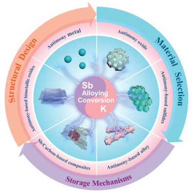
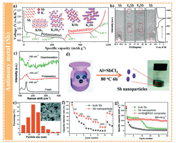
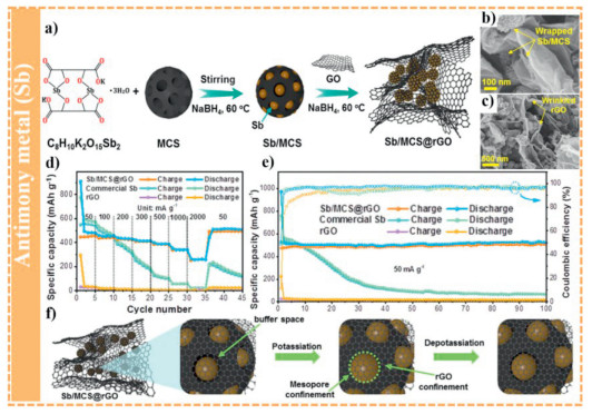
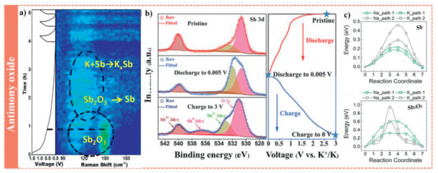
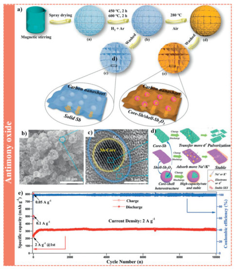
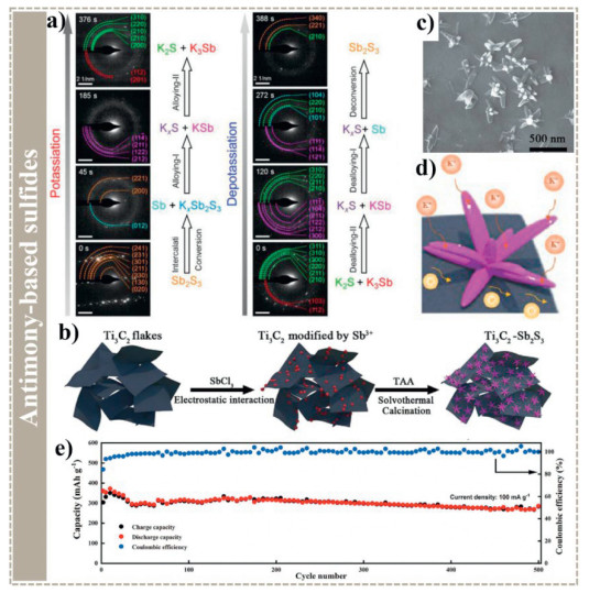
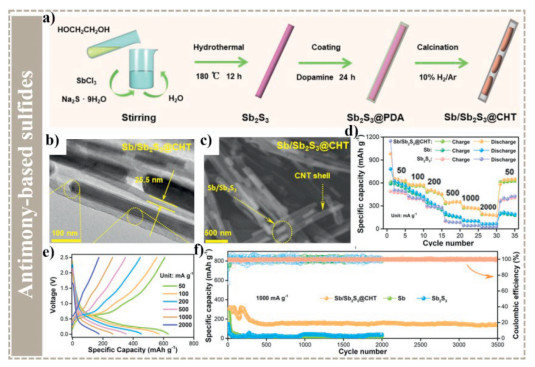
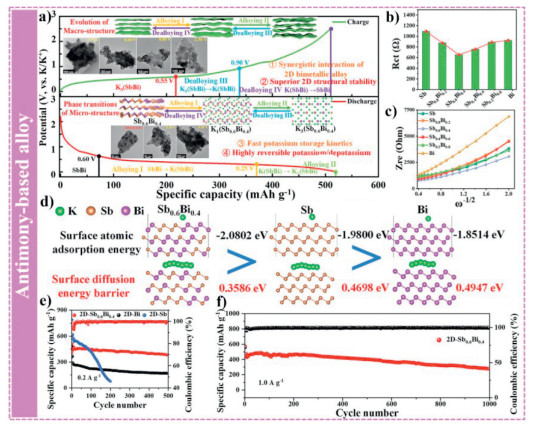
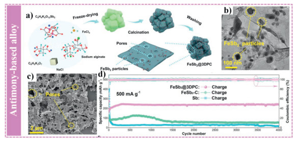
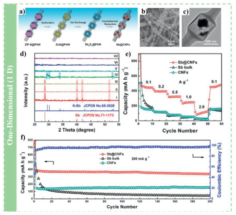
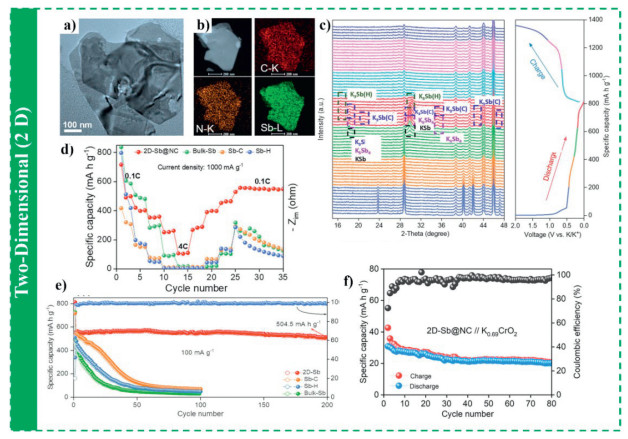
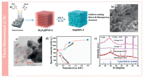
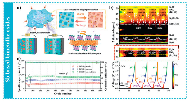
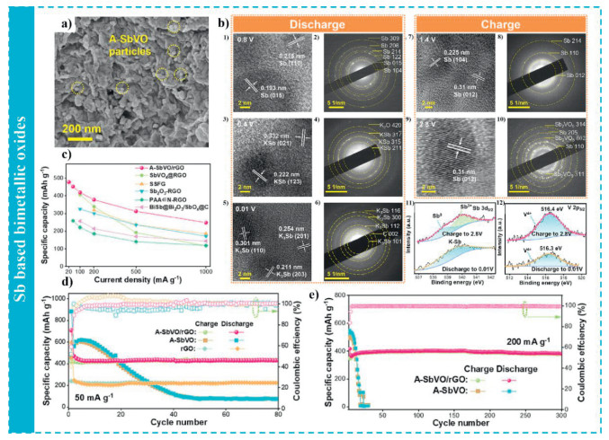
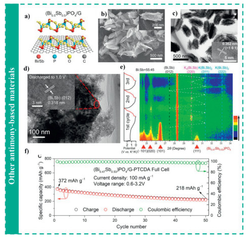
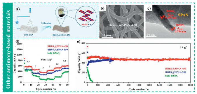
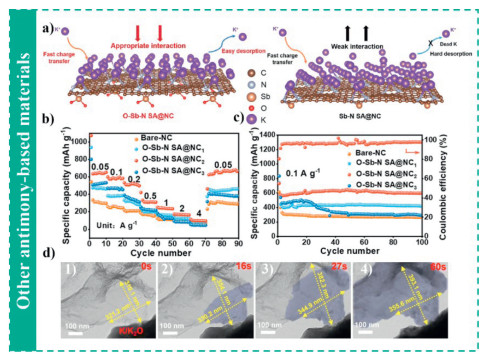
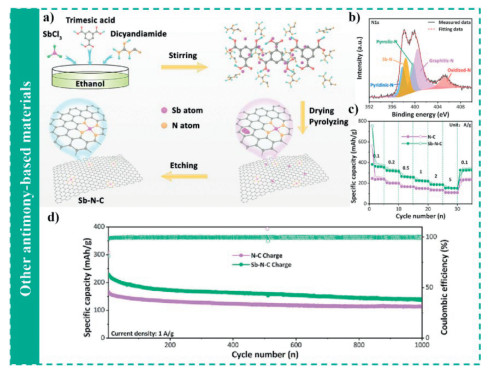


 扫一扫看文章
计量
- PDF下载量: 0
- 文章访问数: 55
- HTML全文浏览量: 5
 下载:
下载:
