Figure 1.
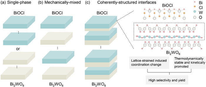
Schematic illustration of catalysts with interlayer configuration. Structure models of (a) single phase Bi2WO6 and BiOCl. (b) Ball-milling sample via mechanical forces. (c) Tandem Bi2WO6-BiOCl with coherent interfaces.
Enhanced photocatalytic CO2 reduction of Bi2WO6-BiOCl heterostructure with coherent interface for charge utilization
Hui Li , Chunlang Gao , Guo Yang , Lu Xia , Wulyu Jiang , Cheng Wu , Kaiwen Wang , Yingtang Zhou , Xiaodong Han

Optimizing carbon fuel consumption and mitigating CO2 greenhouse gas emissions are imperative for fostering the sustainable evolution of human civilization, pivotal in averting the hastening of energy shortages and the exacerbation of global warming [1-5]. The photocatalytic CO2 reduction reaction (CRR) has been considered an environmentally friendly method to "kill two birds with one stone" in the conversion of CO2 for carbon fuel technologies [6-9]. Among the vast array of photocatalysts, bismuth tungstate (Bi2WO6) stands out as a promising member of the Aurivillius family, characterized by its layered perovskite-like structure and appealing band diagram. The energy level of the W 5d orbital presents potential advantages for CO2 binding on the surface of catalysts, while the interaction between the Bi 6s and O 2p orbitals at the top of the valence band leads to a relatively narrow band gap, facilitating light absorption. Typically, photocatalytic efficiency is mainly dependent on light absorption of catalyst, charge transfer, and surface reaction. Tremendous investigations have been devoted to enhancing the charge transfer and optimizing the surface-active sites of Bi2WO6, such as heterojunction construction of Bi2WO6 and BiOX (X=Cl, Br, I) [10-13], downsizing to ultrathin layer or single unit cell [14-18], and doping single atom sites or defects [19-25]. The separation and transfer of electron-hole pairs are recognized to play major roles in all these investigations [26-27]. For instance, Li et al. created oxygen vacancies in plasma-treated Bi2WO6 nanosheets to boost charge transfer, thus enhancing photocatalytic CO2 reduction [28]. Recently, Di and Chen fabricated distorted BiOCl induced by a bilayer thickness of tube geometric structure, and accelerated the photocarrier migration and photocatalytic performance [29]. Moreover, Li et al. reported an electric field would generate via the polarization of the non-uniform charge distribution between different constituent layers of Bi2WO6-BiOCl, and the interlayer carbon impurities can boost separation of electrons and holes immediately after their generation [30]. Nevertheless, single atoms, defects, and interfaces might induce atomic-scale lattice mismatch, which can have a crucial impact on charge transfer dynamics. Especially in two-phase heterojunction, the barrier for charge transfer is inevitable due to the inherent interface. Therefore, the establishment of lattice-matched interfaces, known as coherent interfaces, a term in the field of materials science, is crucial for enhancing interfacial charge transfer in composite materials.
The charge migration in Bi2WO6 semiconductor is another issue of bismuth photocatalysts. The distorted or defective Bi2WO6 can induce a higher charge carrier concentration within catalysts. For instance, Chung found higher concentration of tungsten incorporation into Bi2WO6 can self-doping and lead to a higher bulk carrier density and improved conductivity [31]. Furthermore, the band structure is the thermodynamics prerequisite for the charge transfer. To improve the activity of Bi2WO6, Zhao et al. made a hybrid Ti3C2-Bi2WO6 to increase the efficiency of photocatalytic CO2 reduction, assuring that the interfacial charge transfer ability is dominant [32]. Thus, inspired by the semi-metal phenomena in Bi2WO6 and the charge transfer optimization by hybridization, distorted Bi2WO6 with reduced metal sites can be developed [33]. Although many combinations of Bi2WO6, Bi oxide, BiOX have been widely studied, especially in photocatalytic CO2 reduction, most research focus on the band alignment, regardless of interface contact modification, which is crucial for the inter-phase charge carries transport. in-situ grown heterostructure has promising aspects providing the ideal compatible components for the layered Bi-based structures due to the close packing of atoms at the interface.
In this study, we have proposed a facile method to fabricate a coherent interface aligned Bi2WO6-BiOCl heterostructure, facilitated by the presence of external WO42‒ during hydrothermal synthesis. The resultant in-situ grown BiOCl crystals facilitate the reduction of metal sites of W and Bi, thereby significantly enhancing charge transfer efficiency and consequently improving the photocatalytic CO2 reduction efficiency. Our approach based on atomic lattice matched Bi2WO6-BiOCl, facilitating dynamic charge carrier movement through meticulous interface engineering. This leads to a remarkable photocatalytic efficiency for CO2 reduction to CO, reaching 68.03 µmol g‒1 h‒1. This enhancement can be attributed to optimized surface bonding via strain effects and a rational band alignment that facilitates carrier movement onto the surface.
As depicted in Fig. 1, the structure models of single-phase catalyst, ball-milling sample and Bi2WO6-BiOCl are presented. Single phases in Fig. 1a consist of Bi-O layer, Cl atoms as well as WO42‒ units featuring layered structures. Combined compositions can align surfaces and tune the bandgap to surpass the limit of single catalyst. In Fig. 1b, with the help of mechanically mix process, perovskite-like Bi2WO6 can contact Bi-O layer with BiOCl with physically-built interfaces. The exogenous assembly form rough contact within layers and pristine interfaces were reserved in bulk materials. Beyond hetero-interface between existing structures, the heterostructure of Bi2WO6-BiOCl was synthesized via homology-atom doping strategy in Fig. 1c. Based on the nanosheet reported before [33], we introduce 10% tungstate in acid solution as exogenous part to intercalate in the Bi-O layer. OTAC serve as trapping agent to slow the z-axis growth and chlorine will redistribute owing to the overdosed WO42‒. Through content growth in water for 21 h in 140 ℃, coherent interface was built in halide and WO42‒ layers with co-sharing Bi-O layer acting as transition area. Assemble from solution can build precise alignment to form tandem junctions. According to the previous method [31,33], the interlayer of WO42‒ can be routinely and flexibly coordinated with bismuth-oxygen bond, when strain or exceeding elements was induced in Bi2WO6. Cl atoms was dispersed within octyltrimethyl ammonium chloride (OTAC), while an excess of W elements could trigger the crystallization of Cl component, originating from amorphous state with Bi-O bonding in the crystal growth. Exquisite phase contact between the BiOCl and Bi2WO6 ensure excellent atomic transition across the interface to promote the charge dynamics and band gaps. On the basis of coherent structure, superb CO2 reduction reaction (CRR) performance could be realized.
The components of the tandem Bi2WO6-BiOCl, were validated by X-ray diffraction (XRD) pattern and FTIR spectrum as shown in Fig. S1 (Supporting information). In addition, Fig. S1a demonstrates the XRD patterns of four samples. The characteristic peaks can be identified as BiOCl (JCPDS No. 006–0249) and Bi2WO6 (JCPDS No. 01–073–2020), while Ball-milling sample shows minor peak owing to the poor crystallinity from BiOCl component. Fourier transform infrared spectroscopy (FTIR) of the tandem Bi2WO6-BiOCl catalyst confirm bonds of W-O, Bi-O and Bi-Cl (Fig. S1b), Bi-Cl bond at 1155 and 1458 cm‒1 confirm the incorporation of crystal BiOCl.
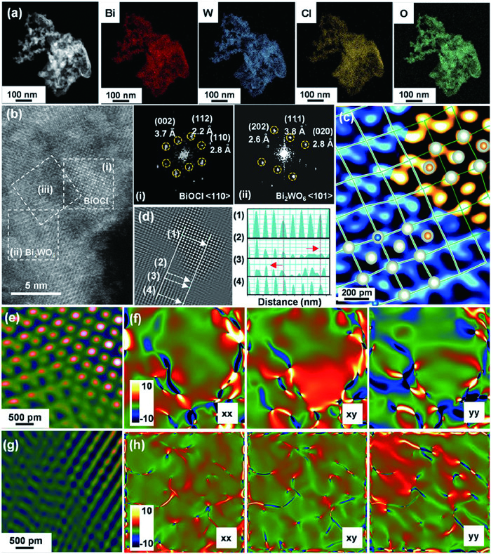
Brunauer-Emmett-Teller (BET) analysis shows that specific surface area of Bi2WO6-BiOCl heterostructure was 31.82 m2/g (Fig. S3a in Supporting information), larger than that of pristine Bi2WO6 with 23.42 m2/g (Fig. S3c in Supporting information), the ball-milling sample possesses a surface area of 33.58 m2/g as depicted in Fig. S3b (Supporting information). The morphology of Bi2WO6-BiOCl was further investigated using aberration-corrected transmission electron microscopy (AC-TEM), as presented in Fig. 2a. The nanosheet shows an uneven and sphere-like surface. Energy dispersive X-ray spectroscopy (EDS) results from Fig. 2 and Fig. S7 (Supporting information) manifest the element dispersion. Bi2WO6-BiOCl showed bright region on the surface, where the location of chlorine and oxygen element follow the morphology. Tungsten was dispersing below while Bismuth was dominant on the surface, fitting the interlayer configuration of WO42‒ layer in the Bi2WO6 substrate. The nanosheet shows an uneven and sphere-like surface. The element dispersion spectra (EDS) of W, Cl, O and Bi demonstrate a mixed distribution of W and Cl within the composite. In Fig. S4 (Supporting information), detailed aggregation of Cl element can be observed in Bi2WO6-BiOCl before and after the reduction reaction process, arising from the BiOCl formation on the Bi2WO6 surface, while Bi2WO6 itself as flat nanosheet. Fig. 2b was obtained via high-angle annular dark field (HAADF) in scanning transmission electron microscopy (STEM). The lattice spacing around 2.80 Å is assigned to the (110) plane of BiOCl as well as (200) planes of Bi2WO6. Corresponding diffraction patterns further elucidate two phases as well for 〈110〉 of BiOCl and 〈101〉 of Bi2WO6. The fast Fourier transform (FFT) filtered image can visualize the phase transitions as false colored image (Fig. 2c). Bi2WO6 is depicted as blue area, while BiOCl occupies the right-up area with orange background. The red rectangle area confirms the consistent transition between Bi2WO6 and BiOCl. The boundary is continuous to reach almost coherent condition. The lattice distortions occur within the contacting area, and the deviation is less than both lattice constants. To unravel the interfacial structure, atomic arrangement and lattice spacing was analyzed. Fig. 2d evidently show the reconstructed boundary area with atomic-scale lattice-match. Lattice spacing was surveyed with four parallel line intensity profiles across the interface. Lines (2) and (3) locates within the boundary, line (1) fits the BiOCl phase and line (4) is close to Bi2WO6. According to the location of two bold line position, the periodic atom arrangement shows little tensile in line (2) and moderate strain in line (3) with the same length, in comparison with line (1). All the mismatched range is within 100 pm. On the basis of lattice arrangements, structure of Bi2WO6-BiOCl can be deduced. The formation of the coherent interface was surveyed, for research on the influence of the interface modulation constructions that exert on the lattice strain engineering. Atomic lattice adjustment in the heterostructure features the strain effects [15], reflecting on the HAADF and geometric phase analysis (GPA)-images. Based on the atomic HAADF image, Ball-milling sample was chosen to contrast with the in-situ grown procedures. In Fig. 2e, smooth atomic contact was labeled as typical balls, while the interface in Fig. 2g was distorted extensively owing to numerous line defects as dislocations. Dislocations in ball-milling sample build disconnected borders between BiOCl and Bi2WO6, displaying as obscure blue pits in the middle of Fig. 2g. As shown in Fig. S11b (Supporting information), dislocations were dominant and distorted the crystal lattice. In terms of GPA strain maps of Fig. 2f, the coherent interface exhibits intensive color contrast, implying the BiOCl undergoes tensile strain as red zone. Blue contrast in the strain field appeared around the border of BiOCl crystal, which means that Bi2WO6 substrate around the -interface suffers compressive interface suffers compressive strain to maintain the coherent structure, although minor lattice distortion appeared. The stress distribution in Fig. 2h shows relatively homogeneous stresses in the ball milling sample, indicating moderate phase connection with shallow color and uniform stress distribution. The strain values that the BiOCl exhibited are more average and smaller. In contrast to Fig. 2f, solid interactions were achieved via the tandem structure with the segregation of BiOCl onto surface. According to results above, we infer that Bi2WO6-BiOCl was atomic-precise formed through the intense strain effects, while the ball-milling sample was filled with dislocations and loose bonded.
To uncover the formation of coherent-matched heterostructure induced by WO42‒, electronic states of elements and coordination environment were surveyed by X-ray photoelectron spectroscopy (XPS) and X-ray absorption spectroscopy (XAS). Fig. 3a distinguish the electron states of W4f. Bi2WO6 consisting of W6+ was set as the reference. More reduced W was detected in the ball-milling sample and Bi2WO6-BiOCl as lower binding energy, indicating the W5+ states arising from the electron injection. Fig. S12a (Supporting information) displayed that reduced species of W5+ appeared in the heterostructure with a ratio of 57.1%, while ball-milling sample occupied less percentage as 42.8%, elucidating better incorporation of tungsten with a majority of reduced tungsten elements. As a result, the coherent interface would be accompanied by the tuning of electronic structure with coordination and valence state changes of tungsten element [18]. The valence states of bismuth and oxygen are depicted in Fig. 3b. In Bi2WO6-BiOCl, the Bi element shifted to lower binding energy. Ball-milling samples also shifted with relatively higher states. Single phases exhibited more oxidized states of Bismuth. Fig. 3c proves the oxide exists as lower binding in Bi2WO6-BiOCl and ball-milling sample. Single BiOCl and Bi2WO6 were more oxidized. Cl elements stay relatively stable with minor changes.
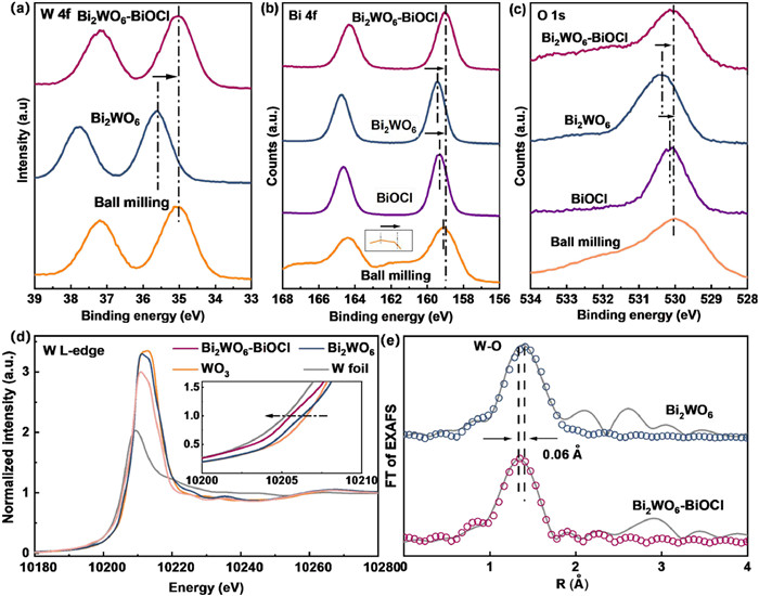
Since the structure of Bi2WO6-BiOCl was induced by WO42‒, whether external tungsten altered the coordination environment was surveyed. As displayed in W LIII-edge X-ray absorption near-edge structure (XANES) spectra (Fig. 3d), peaks of Bi2WO6 and Bi2WO6-BiOCl located between the W foil and WO3. The absorption threshold of Bi2WO6-BiOCl shifted to lower energy than Bi2WO6, as well as lower white line intensity, indicating an increase of reduced state of tungsten as W5+. The XPS results presented before fits well with XANES result. The Fourier-transformed extended X-ray absorption fine structure (FT-EXAFS) spectra (Fig. 3e) displays that the main peak of W-O in Bi2WO6-BiOCl is shorter than that of pristine Bi2WO6 by 0.06 Å, implying the dense coordination of tungsten and oxygen. The fitted curves confirmed the octahedral model of WO42‒. Detailed results are summarized in Table S1 (Supporting information). Compared with Bi2WO6, the Bi2WO6-BiOCl sample has one more coordination number of planar W-O bond as 4.8, and simultaneously has one less coordination number of vertical W-O bonding. The distorted configuration may result from z-axis coordination with less oxygen atoms while the planar coordination number increases. Shorter bond length justifies spatially change within the strained Bi2WO6, whose confined structure benefits the crystallization of Cl into BiOCl [34]. The compressed geometry of WO42‒ and shorter W-O bonding was consistent with HAADF-STEM parameters, aside from chemical states analysis, the coordination of tungsten was examined by XAS. Since the distorted W-O and Bi-O both have lower binding energy than that in pristine Bi2WO6, the external WO42‒ is likely to trigger the reconstruction of Bi2WO6 nanosheet with distortion interlayer during the synthesis. Meanwhile, in-situ grown BiOCl crystal could compete Bi-O bonding with neighbored WO42‒ unit to occupy the z-axis room to form heterostructure, consequently coherent interface stabilizes the Bi-O layer with more reduced metal-oxygen bonding.
To further investigate photocatalytic CO2 reduction performance of Bi2WO6-BiOCl, a gas-solid interfacial CO2 photo-reduction was performed to evaluate the photocatalytic efficiency and selectivity. No external sacrifice agent was induced in the reaction process, and all the tests were conducted with AM 1.5 light. Fig. 4a shows the Bi2WO6-BiOCl has a CO yield of 68.03 µmol g‒1 h‒1, which is 5.62 times and 5.76 times larger than that of pristine Bi2WO6 and BiOCl, respectively. The efficiency reaches superior performance comparing with the literature reported bismuth tungstate structures as list in Table S3 (Supporting information). Moreover, the Bi2WO6-BiOCl heterostructure with atomic-scale lattice-match exhibits a greater performance than that of ball-milling sample with numerous dislocations, suggesting the lattice-matched interface contributes enhanced activity.
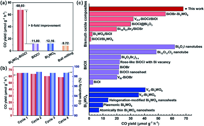
Performance of Ball-milling sample were inferior to single phase, which may arise from loosen contact around interface. Furthermore, Fig. 4b shows the selectivity of the photocatalytic CO2 reduction reactions, the products were mainly CO with a minor amount of CH4, the electron selectivity of Bi2WO6-BiOCl is almost 98%. The reactivity of Bi2WO6-BiOCl for CRR was superb and highly selective to CO Additionally, the stability test (Fig. 4b) illustrates that the Bi2WO6-BiOCl is relatively stable [36], while the catalytic performance can maintain 90% above. In Fig. 4c, compared with current works of pure Bi-based materials, the reactivity ranks among the top catalysts.
To disclose the mechanism for the enhanced efficiency of Bi2WO6-BiOCl, the photoelectric properties and kinetic pathways of photo carriers were investigated. We surveyed photocurrent tests and electrochemical impedance spectroscopy (EIS) to deduce the charge transfer resistance. Fig. 5a showed a significant higher photocurrent by almost 4–5 times larger than those of pristine Bi2WO6 and BiOCl. The ball-milling sample was insufficient for carrier transportation as almost zero current density. As exhibited in Fig. S11b, dislocations serving as trapping sites can accumulate charge carriers to combine before they contribute to the photocurrent, leading to the drastic decrease in the overall photocurrent efficiency. In ball-milling sample, mismatched interface inhibited sufficiently utilization of electrons, resulting poor photocurrent performance. In Fig. 5b, the Nyquist plots of Bi2WO6-BiOCl shows lower arc-resistance compared with those of BiOCl and Bi2WO6, indicating the charge transfer can be improved between the surfaces. Bi2WO6 was less conductive than BiOCl with bigger arc-resistance.
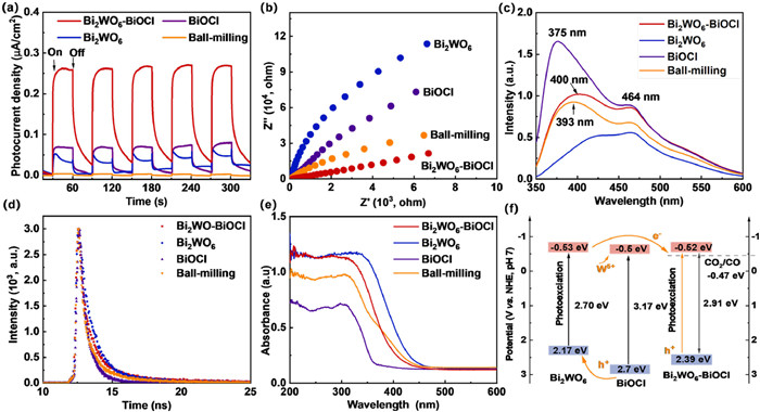
The reason why ball-milling sample exhibited lowest arc resistance may result from the poor crystallinity owing to the dominant dosage of OTAC surfactant, for the amorphous contributes to higher conductivity in EIS and broad peak in XRD [25]. Wholly covered surface of BiOCl in the ball-milling sample determine the performance. Bi2WO6-BiOCl originates from substrate of Bi2WO6, consistent Bi2WO6 determine the inferior electrochemical impedance.
Photoluminescence (PL) was conducted to reveal the separation of electron-hole pairs. As shown in Fig. 5c. Peaks around 464 nm relate to isolated vacancy bi defects, while the 393 and 400 nm peaks of Bi2WO6-BiOCl and ball-milling sample were red shift than that of BiOCl at 375 nm, indicating electronic coupling between nanocrystals when they are packed into a composite. All the intensities were elevated in contrast with Bi2WO6 sample, arising from the BiOCl crystal upon the surface [36,38]. Furthermore, a kinetic investigation of transient photoelectron's behavior on Bi2WO6-BiOCl was also accomplished. Analysis of the curves with re-convolution fitting manifests that the decays of each sample follow a bi-exponential model with τ1 and τ2 (Fig. 5d and Table S4 in Supporting information). In pristine Bi2WO6, the photo generated electrons from WO42- layer shall move to the surface of the nanosheet to participate in the reaction; such a long migration path may increase the probability of electron-hole recombination and lower the photocatalytic activity [33]. Interestingly, Bi2WO6-BiOCl and ball-milling samples demonstrates less τ1 and τ2 than those of single phases. Reduced τ values indicate that new electron channels were built, resulting in no obvious recombination suppression of electron-hole separation. τ2 was greatly reduced in Bi2WO6-BiOCl than other samples, which confirms that the interface pronounced to boost the separation [37]. In matched-lattice epitaxy in Bi2WO6-BiOCl, and fine electron channel was in-built across the coherent interface. As for ball-milling sample, photocurrent transportation was severely hampered, although better EIS and PL performance [38]. In ball-milling sample, numerous dislocations around interface trap the carriers, while Bi2WO6-BiOCl only build smooth interface. We presume that interface and defects both inhibit the recombination of electron and holes. In summary, the mechanism of charge transfer enhancement in Bi2WO6-BiOCl can be ascribed to the reduced tungsten with more W5+ states and reduced Bi atoms, which is also consistent with previous researches that this conductivity improves with the presence of the semi-metal of W5+ sites and distorted W-O unit cell [31,33,39]. Fig. 5e shows UV–vis spectra of the samples, in terms of the band gap in Fig. S14 (Supporting information), the 2.91 eV of composites is between 2.70 eV and 3.17 eV, which corresponds to BiOCl and Bi2WO6 [40-42]. The energy level results are shown in Fig. 5f and Table S5 (Supporting information). In the heterostructure, the induced BiOCl phase alters the Bi2WO6 nanosheet and the electron flows to the BiOCl phase. N type BiOCl and Bi2WO6 will bend upward in both CB and VB band to transport charge carriers. Energy level in the heterostructure is examined to confirm the thermodynamics.
To verify the dynamic reaction process and the reaction route of CO2 to CO, in-situ FTIR spectra were conducted to elucidate the intermediates. The reaction parameters were recorded with the interval of 6 min. As depicted in Figs. 6a and b, peaks concerning with the adsorbed species of monodentate carbonate (m-CO32‒) located at 1560 cm‒1and 1398 cm‒1, while bicarbonate (HCO3‒) peaks located at 1472 cm‒1 and 1523 cm‒1. Peaks at 1697 cm‒1 and 1620 cm‒1 resulted from the vibration of bidentate carbonates (b-CO32‒) [43]. All peaks associated with CO32‒ species were enhanced in intensity after light. Particularly, during the reaction period, the concentration of COOH* (1550 cm‒1) are significantly increased, indicating which were the key intermediates during the process of CO2 to CO [44]. Besides, the peaks at 1360 cm‒1 were assigned to the specie formate (HCO2‒) [45,46]. Therefore, based on the data from in situ FT-IR spectra, the possible reaction path for the catalytic process was proposed as follows (Eqs. 1-4).
|
|
(1) |
|
|
(2) |
|
|
(3) |
|
|
(4) |
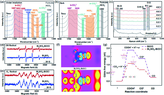
As shown in Fig. 6c, peaks range from 830 to 900 cm‒1 can be assigned to the peroxo-species. Signals at 139 cm‒1 and 192 cm‒1 arises from A1g internal stretching and Eg vibration of Bi-Cl bond in the crystal BiOCl. The peroxo bond with metals around 817 cm‒1 appeared with Bi-Cl bond during the reaction, along with O—O stretching bond located at 901 cm‒1 [47-49]. All the four peaks were not observed in the pristine sample, indicating that the reaction proceeds with Bi-Cl and surface water to form the metal-peroxo complex. The bands at 784 and 817 cm‒1 are associated with the antisymmetric and symmetric Ag modes of the terminal O-W-O bond, respectively. O-W-O bond exhibited reduced intensity at 817 cm‒1 and shorter length around 784 cm‒1, reflecting more distorted bridge bonds in the WO6 octahedral layers [33,50]. Hence, the peroxo species produced with Bi-Cl bond simultaneously in the in-situ reaction process, while W-O bonds showed disorder and less active in the reaction process. We can infer that Cl take part in the reaction process to form O—O and peroxo species, surface anchored BiOCl provide the active sites for the intermediates. Electron spin resonance spectrum in Figs. 6d and e showed the reaction intermediate was OH and O2‒ radicals [35,48]. Fig. 6f displayed the charge distribution, and BiOCl was content with electrons rather than Bi2WO6 in the heterostructure. Combined with the efficient charge dynamics and band alignment, density functional theory (DFT) calculations were further conducted to verify the reactivity of Bi2WO6-BiOCl. As shown in Fig. 6g, CO2 underwent three steps to form CO, where COOH* was the intermediate. Both the active sites are on the surface of BiOCl for two samples, and the process of CO2 to COOH was the most endothermic step. In Bi2WO6-BiOCl, the electron flowed from Bi2WO6 to BiOCl, which enabled more electrons to participate into the surface reaction. The energy difference was as high as 1.895 eV for BiOCl from CO2 to COOH. In comparison, the most endothermic step on Bi2WO6-BiOCl was the formation of COOH* intermediate with an energy barrier of 1.085 eV The reduced energy value even reached 0.810 eV, which further uncovered the mechanisms of excellent photocatalytic CO2 reduction on Bi2WO6-BiOCl. The charge distribution in Fig. S18 (Supporting information) showed CO2 adsorbed on the Bi2WO6-BiOCl was more active on the surface [51,52].
In summary, the construction of in-situ grown Bi2WO6-BiOCl heterostructure with coherent interface was achieved via tungstate doping, whose lattice enriched with abundant reduced metal sites with atomic precision. The catalyst exhibits an enhanced photocatalytic efficiency of 68.03 µmol g−1 h−1 with 98% selectivity to CO production, which is higher than those of pristine BiOCl and Bi2WO6, propelling itself as the state-of-the-art Bi-based photocatalyst. The promoted performance can be ascribed to the enhanced electron transfer between the atomic level coherent Bi2WO6-BiOCl interface, which was confirmed by local coordination environment and valence analysis. The DFT and in-situ FT-IR tests reveal the lower energy barriers of rate-determining step the conversion of adsorbed CO2 to COOH* over the Bi2WO6-BiOCl with coherent interface. This coherent interface engineering route can optimize interfacial charge transfer dynamics beyond energy alignment engineering.
Hui Li: Writing – original draft, Investigation, Formal analysis, Conceptualization. Chunlang Gao: Visualization, Resources, Data curation. Guo Yang: Visualization, Validation, Software. Lu Xia: Software, Methodology, Formal analysis, Data curation. Wulyu Jiang: Writing – review & editing, Visualization, Supervision, Software, Formal analysis, Conceptualization. Cheng Wu: Visualization, Formal analysis. Kaiwen Wang: Writing – review & editing, Resources, Data curation. Yingtang Zhou: Writing – review & editing, Writing – original draft, Validation, Supervision, Resources, Data curation. Xiaodong Han: Writing – review & editing, Validation, Supervision, Resources, Funding acquisition, Data curation.
This work was supported by the National Key R&D Program of China (No. 2021YFA1200201), the Beijing Outstanding Young Scientists Projects (No. BJJWZYJH01201910005018), The Basic Science Center Program for Multiphase Evolution in Hypergravity of the National Natural Science Foundation of China (No. 51988101), the National Natural Science Foundation of China (Nos. 52071003 and 91860202).
Supplementary material associated with this article can be found, in the online version, at doi:
C. Vogt. C, M. Monai, G.J. Kramer, et al., Nat. Catal. 2 (2019) 188–197. doi: 10.1038/s41929-019-0244-4
S. Zhang, Q. Fan, R. Xia, et al., Acc. Chem. Res. 53 (2020) 255–264. doi: 10.1021/acs.accounts.9b00496
D.H. Nam, P. De. Luna, A. Rosas-Hernández, et al., Nat. Mater. 19 (2020) 266–276. doi: 10.1038/s41563-020-0610-2
S. Xu, E.A. Carter, Chem. Rev. 119 (2018) 6631–6669.
X. Li, J. Yu, M. Jaroniec, et al., Chem. Rev. 119 (2019) 3962–4179. doi: 10.1021/acs.chemrev.8b00400
S. Ali, M.C. Flores A. Razzaq, et al., Catalysts. 9 (2019) 727. doi: 10.3390/catal9090727
H. Yu, J. Li, Y. Zhang, et al., Angew. Chem. Int. Ed. 58 (2019) 3880–3884. doi: 10.1002/anie.201813967
S. Li, L. Bai, N. Ji et al., J. Mater. Chem. A. 8 (2020) 9268–9277. doi: 10.1039/d0ta02102d
Y. Hu, R. Abazari, S. Sanati, et al., ACS Appl. Mater. Interfaces 5 (2023) 37300–37311. doi: 10.1021/acsami.3c04506
M. Li, S.X. Yu, H. Huang, et al., Angew. Chem. Int. Ed. 58 (2019) 9517–9521. doi: 10.1002/anie.201904921
Z. He, Y. Shi, C. Gao, et al., J. Phys. Chem. C. 118 (2014) 389–398. doi: 10.1021/jp409598s
S. Shenawi-Khalil, V. Uvarov, S. Fronton, et al., J. Phys. Chem. C 116 (2012) 11004–11012. doi: 10.1021/jp3009964
C. Chang, L. Zhu, S. Wang, et al., ACS Appl. Mater. Interfaces 6 (2014) 5083–5093. doi: 10.1021/am5002597
M. Sun, M. Chen, X. Cui, et al., Surf. Interfaces 42 (2023) 103313. doi: 10.1016/j.surfin.2023.103313
Z. Hou, C. Cui, Y. Li, et al., Adv. Mater. 35 (2023) 2209876. doi: 10.1002/adma.202209876
Y. Zhou, Y. Zhang, M. Lin, et al., Nat. Commun. 6 (2015) 8340. doi: 10.1038/ncomms9340
F. Chen, Y. Zhang, H. Huang, Chin. Chem. Lett. 34 (2023) 107523. doi: 10.1016/j.cclet.2022.05.037
J. Di, C. Chen, S.Z. Yang, et al., Nat. Commun. 10 (2019) 2840. doi: 10.1038/s41467-019-10392-w
C. Hu, H. Huang, Acta Phys. Chim. Sin. 39 (2023) 2212048. doi: 10.3866/pku.whxb202212048
X. Jin, Y. Xu, X. Zhou, et al., ACS Mater. Lett. 3 (2021) 364–371. doi: 10.1021/acsmaterialslett.1c00091
X. Luo, R. Abazari, M. Tahir, et al., Coordin. Chem. Rev. 461 (2022) 214505. doi: 10.1016/j.ccr.2022.214505
L.J. McGilly, A. Kerelsky, N.R. Finney, et al., Nat. Nanotechnol. 15 (2020) 580–584. doi: 10.1038/s41565-020-0708-3
F. Rao, Y. An, X. Huang, et al., ACS Catal. 13 (2023) 2523–2533. doi: 10.1021/acscatal.2c04954
Q. Bie, H. Yin, Y. Wang, Chin. J. Catal. 57 (2024)123–132. doi: 10.1016/S1872-2067(23)64591-7
B. Aziz S, S. Marf A, E.M.A. Dannoun, et al., Polymers 12 (2020) 2184. doi: 10.3390/polym12102184
Z. Li, G. Zhu, W. Zhang, et al., Chem. Eng. J. 452 (2023) 139378. doi: 10.1016/j.cej.2022.139378
J. Cao, J. Wang, Z. Wang, et al., Surf. Interfaces. 45 (2024) 103875. doi: 10.1016/j.surfin.2024.103875
Q. Li, X. Zhu, J. Yang, et al., Inorg. Chem. Front. 7 (2020) 597–602. doi: 10.1039/c9qi01370a
J. Di, C. Zhu, M. Ji, et al., Angew. Chem. Int. Ed. 57 (2018) 14847–14851. doi: 10.1002/anie.201809492
J. Li, L. Cai, J. Shang, et al., Adv. Mater. 28 (2016) 4059–4064. doi: 10.1002/adma.201600301
H.Y. Chung, C.Y. Toe, W. Chen, et al., Small 17 (2021) 2170183. doi: 10.1002/smll.202170183
D. Zhao, C. Cai. Mater. Chem. Front. 3 (2019) 2521–2528. doi: 10.1039/c9qm00570f
X. Cao, Z. Chen, R. Lin, et al., Nat. Catal. 1 (2018) 704–710. doi: 10.1038/s41929-018-0128-z
J. He, X. Wang, S. Lan, et al., Appl. Catal. B: Environ. 317 (2022) 121747. doi: 10.1016/j.apcatb.2022.121747
C. Yang, Y. Wang, J. Yu, et al., ACS Appl. Energy Mater. 4 (2021) 8734–8738. doi: 10.1021/acsaem.1c02122
Y. Zhang, Z. Xu, Q. Wang, et al., Appl. Catal B: Environ. 299 (2021) 120679. doi: 10.1016/j.apcatb.2021.120679
Y. Zhou, Z. Tian, Z. Zhao, et al., ACS Appl. Mater. Interfaces 3 (2011) 3594–3601. doi: 10.1021/am2008147
J. Huang, G. Tan, H. Ren, et al., ACS Appl. Mater. Interfaces 6 (2014) 21041–21050. doi: 10.1021/am505817h
J. Zhang, Z. Li, J. He, et al., ACS Catal. 13 (2023) 785–795. doi: 10.1021/acscatal.2c05545
X. YingáKong, Y. YeeáChoo, A. KaháSoh, et al., Chem. Commun. 52 (2016) 14242–14245. doi: 10.1039/C6CC07750A
Y. Liu, D. Shen, Q. Zhang, et al., Appl. Catal B: Environ. 283 (2021) 119630. doi: 10.1016/j.apcatb.2020.119630
Y. Wang, T. Chen, F. Chen, et al., Sci. China Mater. 65 (2022) 3497–3503. doi: 10.1007/s40843-022-2093-x
J. Wu, K. Li, S. Yang, et al., Chem. Eng. J. 452 (2023) 139493. doi: 10.1016/j.cej.2022.139493
N. Li, B. Wang, Y. Si, et al., ACS Catal. 9 (2019) 5590–5602. doi: 10.1021/acscatal.9b00223
S.S. Bhosale, A.K. Kharade, E. Jokar, et al., J. Am. Chem. Soc. 141 (2019) 20434–20442. doi: 10.1021/jacs.9b11089
J. Meng, Y. Duan, S. Jing, et al., Nano Energy 92 (2022) 106671. doi: 10.1016/j.nanoen.2021.106671
Y. Bai, L. Ye, T. Chen, et al., Appl. Catal B: Environ. 203 (2017) 633–640. doi: 10.1016/j.apcatb.2016.10.066
J. Li, B. Huang, Q. Guo, et al., Appl. Catal B: Environ. 284 (2021) 119733. doi: 10.1016/j.apcatb.2020.119733
X. Zhu, G. Zhou, J. Yi, et al., ACS Appl. Mater. Interfaces 13 (2021) 39523–39532. doi: 10.1021/acsami.1c12692
X. Zhang, H. Su, P. Cui, et al., Nat Commun. 14 (2023) 7115. doi: 10.1038/s41467-023-42887-y
N.V. Maksimchuk, G.M. Maksimov, V.Y. Evtushok, et al., ACS Catal. 8 (2018) 9722–9737. doi: 10.1021/acscatal.8b02761
L. Wang, X. Zhao, D. Lv, et al., Adv. Mater. 32 (2020) 2004311. doi: 10.1002/adma.202004311

Figure 1 Schematic illustration of catalysts with interlayer configuration. Structure models of (a) single phase Bi2WO6 and BiOCl. (b) Ball-milling sample via mechanical forces. (c) Tandem Bi2WO6-BiOCl with coherent interfaces.

Figure 2 STEM characterization of Bi2WO6-BiOCl. (a) HAADF-STEM image and elemental dispersive scanning of composite with Bi, O, W, Cl. (b) Atomic resolution HAADF-STEM image for (ⅰ) BiOCl and (ⅱ) Bi2WO6 phase, the (ⅲ) area was selected to manifest the interface structure. Diffraction patterns of (ⅰ) BiOCl and (ⅲ) Bi2WO6 were shown right of the panel. (c) FFT-filtered atomic resolution image using two sets of diffraction spots in red area. The lattice distortions can be visualized by comparing the array disorder. (d) FFT-filtered atomic image of left-up area in Fig. 2b. Four parallel lines were selected in BiOCl (1), interface (2), interface (3) and Bi2WO6 (4) to check atomic deviation profile around the interface. (e, f) FFT-filtered atomic resolution image visualization of Fig. 2c and corresponding GPA image of Bi2WO6-BiOCl. (g, h) False color image around the interface and GPA image for the ball-milling sample.

Figure 3 Electronic states of elements and local environmental coordination of W. (a) The XPS peak of W 4f for Bi2WO6-BiOCl. (b, c) was XPS of Bi 4f and O 1s. (d) The W LⅢ-edge XANES spectra. (e) The corresponding k3-weighted FT spectra of Bi2WO6-BiOCl, Bi2WO6 was used as reference sample.

Figure 4 Photocatalytic CO2 reduction (a) efficiency, (b) selectivity and stability of Bi2WO6-BiOCl composite, the reference samples involve ball-milling sample, pristine Bi2WO6 and pristine BiOCl. (c) The performance comparison of CO yield with pure Bi-based materials.

Figure 5 Photocarrier separation and migration. (a) Photo-current performance and (b) Nyquist plots. (c) PL spectra. (d) Transient time-resolved PL decay spectra. (e) UV–vis spectra of four samples. (f) Band diagram of single phase and Bi2WO6-BiOCl.

Figure 6 Dynamic characterization of CO2 reduction. In situ FTIR spectrum of Bi2WO6-BiOCl heterostructure under light (a) and dark (b) conditions. The time interval was 15 min. (c) In situ Raman spectrum Bi2WO6-BiOCl with step-wise voltage in the electro CO2 reduction process. Electron spin resonance (ESR) test of Bi2WO6-BiOCl with (d) hydroxyl radicals and (e) superoxide radicals. (f) Charge distribution of CO2 on BiOCl and Bi2WO6-BiOCl. (g) The free energy diagram for CO2 reduction to CO over Bi2WO6-BiOCl and pure BiOCl phase.

 扫一扫看文章

扫一扫关注我们
 DownLoad:
 下载:
下载:
 下载:
下载: