Citation:
Xiaoxi Zhao, Qingyun Dou, Pei Tang, Bingjun Yang, Qunji Xue, Xingbin Yan. In-situ construction of solid electrolyte interphase for stable zinc anode via synergy of electrochemical reduction and chemical precipitation[J]. Chinese Chemical Letters,
2025, 36(11): 110422.
doi:
10.1016/j.cclet.2024.110422
In-situ construction of solid electrolyte interphase for stable zinc anode via synergy of electrochemical reduction and chemical precipitation
English
In-situ construction of solid electrolyte interphase for stable zinc anode via synergy of electrochemical reduction and chemical precipitation
Research Center of Resource Chemistry and Energy Materials, State Key Laboratory of Solid Lubrication, Lanzhou Institute of Chemical Physics, Chinese Academy of Sciences, Lanzhou 730000, China
b.
School of Materials Science and Engineering, Sun Yat-Sen University, Guangzhou 510275, China
c.
Center of Materials Science and Optoelectronics Engineering, University of Chinese Academy of Sciences, Beijing 100049, China
Received Date:
26 June 2024 Accepted Date:
05 September 2024 Revised Date:
04 September 2024 Available Online:
15 November 2025
Abstract:
Aqueous zinc ion batteries (ZIBs) feature high theoretical capacity, low cost, and high safety, but they suffer from moderate reversibility arising from electrolyte decomposition, Zn corrosion/passivation, and dendrite growth. To address this issue, an effective strategy is to construct a functional solid electrolyte interface (SEI) in situ. However, this is substantially challenging owing to the severe hydrogen evolution reaction (HER) and a lack of substances that can be decomposed to form SEI in the aqueous electrolytes. Herein, we propose the fabrication of a stable SEI in situ via a synergistic electrochemical reduction-chemical precipitation approach. By chemically capturing the hydroxide ions (OH−) from HER, fatty acid methyl ester ethoxylate (FMEE), as an aqueous electrolyte additive, undergoes ester group hydrolysis following by a combination with Zn2+ to form insoluble fatty acid-zinc, enabling intelligent growth of a SEI on the Zn anode surface. As a result, the enhanced Zn anode exhibits a prolonged cycling life of up to 2700 h at 1 mA/cm2 and 1 mAh/cm2. The Zn-V2O5 full cell with the designed electrolyte demonstrates excellent rate capability and significantly improved cycling stability. This study presents a simple and practical strategy for in-situ formation of SEI in aqueous electrolytes, advancing the development of high-performance aqueous batteries.
In recent years, the demand for high-efficiency and eco-friendly energy storage technologies has propelled the rapid advancement of rechargeable batteries. Non-aqueous lithium-ion batteries (LIBs) are the predominant rechargeable power sources in the market. However, owing to the limited lithium reserves, high cost, and potential safety hazard of LIBs, the development of alternative electrochemical energy storage technologies has been stimulated [1]. Among these, aqueous zinc ion batteries (ZIBs) have emerged as one of the most promising candidates because of their low cost, non-flammability, and environmental friendliness [2,3]. Zn metal as anode possesses significant advantages such as abundant reserves (100 times that of lithium), high theoretical specific capacity (820 mAh/g and 5855 mAh/cm3), low redox potential (−0.76 V vs. standard hydrogen electrode (SHE)), compatibility with water, and high safety. However, the notorious Zn dendrite growth and side reactions (such as hydrogen evolution reaction (HER), corrosion, and passivation) will cause internal short circuits and low coulombic efficiency (CE) of Zn stripping/ plating [4-10].
An effective SEI can prevent continuous decomposition of water by blocking the contact between electrolyte and Zn anode, and regulate ion flux to promote uniform Zn deposition without dendrite growth [11]. So far, various strategies have been employed to construct SEIs for Zn anode, which are generally categorized as artificial SEIs and in-situ SEIs. Artificial SEIs are obtained by physically coating the Zn anode surface with inorganic layers [12-16], organic layers [17-20], and inorganic-organic hybrid layers [21-24]. However, they tend to be damaged and detached from the Zn anode surfaces attributed to the loose adhesion between artificial SEIs and Zn anodes, eventually losing their protective function. Moreover, it is impossible to completely prevent contact between H2O and Zn anodes owing to the inherent voids in inorganic nano-coatings and the flexibility of polymers [25]. In view of this, in-situ fabrication of functional SEIs on the Zn anode surface is promising in addressing the aforementioned issues. Inspired by the non-aqueous batteries, the chemical compositions of the SEIs are closely related to the electrolytes, mainly from the decomposition of the organic solvents and/or salt anions [26]. However, it is not an easy task to construct a SEI in aqueous ZIBs. This is because the high reduction potential of H2O makes the HER occur before the decomposition of anions [27,28]. The vigorous H2 evolution on the Zn anode surface impedes the growth of the SEI and continuously damages the gain. Additionally, the HER increases the local pH value near the Zn anode, leading to the formation of by-products such as alkaline zinc salts and zinc oxide [29]. In recent years, it has been demonstrated that the in situ formation of SEIs can be achieved in ZIBs using organic electrolytes [30], organic-water hybrid electrolytes [31-34], and highly concentrated aqueous electrolytes [35,36]. The construction of anion-derived SEIs and organic-based SEIs greatly relies on high proportions of salts and organic solvents in the aqueous electrolytes. However, this undoubtedly undermines the inherent benefits of aqueous electrolytes, such as low cost, low viscosity, and environmental compatibility. Moreover, various additives, such as KPF6 [37], alkylammonium salts [38], saccharin (SAC) [39], and Zn(H2PO4)2 [40] have been introduced into aqueous electrolytes to construct in-situ SEIs. Nevertheless, the selection of additives is a complex subject, requiring simultaneous consideration of various factors such as solubility, cost, scalability, SEI effectiveness, safety, and battery capacity. Overall, it is crucial yet challenging to achieve high-quality and high-efficiency in-situ formed SEIs in aqueous electrolytes for realizing the practical applications of aqueous ZIBs.
Herein, the by-product of HER, hydroxide ions (OH−), is utilized to trigger the in-situ formation of SEI on Zn anode achieving the aim of "turning trash into treasure". To this end, a nonionic surfactant, fatty acid methyl ester ethoxylate (FMEE), is introduced as an electrolyte additive. The ester group of FMEE can be hydrolyzed by OH− [41], and the generated fatty acid anions combine with Zn2+ ions to form solid fatty acid-zinc at the electrode/electrolyte interface, thereby enabling the in-situ formation of a dense and uniform fatty acid-zinc-based SEI. Consequently, Zn||Zn symmetric cell in the FMEE-containing electrolyte exhibits stable long-term cycling for 2700 h at a current density of 1 mA/cm2, and Zn||Cu asymmetric cell achieves a high CE of 99.04%, while in zinc perchlorate (Zn(ClO4)2) electrolyte, both the Zn||Zn cell and Zn||Cu cell fail quickly. This superior performance is correlated with the formed SEI on Zn anode significantly inhibiting Zn dendrite growth and side reactions. The practical application of the modified electrolyte is further demonstrated by the notably improved cycling stability of Zn-V2O5 full cell.
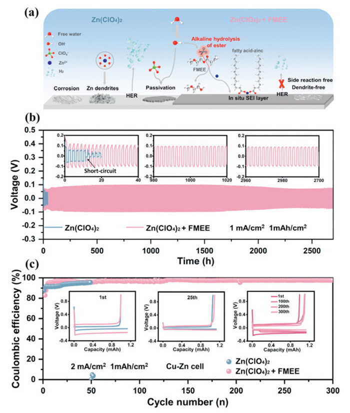
To address the inherent issues of the Zn anode, we propose the introduction of a nonionic surfactant, FMEE, as electrolyte additive to in situ construct an SEI rich in fatty acid-zinc (Fig. 1a). FMEE consists of hydrophilic polyethylene oxide chain and hydrophobic fatty acid ester (Fig. S1 in Supporting information, exhibiting good water solubility, Zn2+ compatibility, and biodegradability [42].
Figure 1
Figure 1.
Electrochemical performance of Zn anodes in Zn(ClO4)2 and Zn(ClO4)2 + FMEE electrolytes. (a) Diagram of Zn anode surface evolution and interfacial layer formation mechanism in two electrolytes. (b) Long-term constant current cycling performance of Zn||Zn symmetric cells using two electrolytes at 1 mA/cm2 and 1 mAh/cm2. Insets show magnified views of the voltage profiles. (c) Coulombic efficiency (CE) of Zn deposition/stripping in Zn||Cu asymmetric cells using two electrolytes at 2 mA/cm2 and 1 mAh/cm2. Insets show the corresponding voltage curves at different cycle numbers.
As HER progresses, OH− accumulates on Zn anode surface. The ester groups in FMEE can undergo hydrolysis under the catalysis of OH− [41], and the resulting ions combine with Zn2+ to generate insoluble fatty acid-zinc [(CH3(CH2)mCOO)2 Zn] in aqueous electrolytes, the specific reactions are as follows:
As a matter of fact, the locations on the Zn anode surface where HER occurs are accompanied by local accumulation of by-products, and these active sites are most in need of "passivation". In this strategy, FMEE can capture OH− at the right locations and construct in situ fatty acid-zinc rich SEI, achieving high-quality passivation to ensure the SEI is uniform and dense. Therefore, through the combination of electrochemical decomposition and chemical deposition, we can turn prior disadvantages into advantages.
To validate our hypothesis, FMEE was added to aqueous electrolyte containing zinc sulfate (ZnSO4) and Zn(ClO4)2. As shown in Fig. S2 (Supporting information), the Zn(ClO4)2 + FMEE is a clear solution, while the ZnSO4 + FMEE is consistently a turbid solution. Therefore, we chose Zn(ClO4)2-based system as the study subject. The designed electrolytes are denoted as Zn(ClO4)2 + x% FMEE, where x% represents the mass concentration of FMEE in the total electrolyte (wt%).
The optimal amount of FMEE in 1 mol/L Zn(ClO4)2 was determined to be 2% that allowed the best electrochemical stability of Zn||Zn symmetric cell (Fig. S3 in Supporting information). An excess of FMEE additive accelerates its hydrolysis, producing water-insoluble fatty acid (Fig. S4 in Supporting information), which would induce poor cycling stability of the cell. Also, as shown in Fig. S5 (Supporting information), the ionic conductivities of the Zn(ClO4)2 and Zn(ClO4)2 + FMEE electrolytes were almost the same, indicating that the added FMEE had little effect on the ion diffusion. As shown in Fig. 1b, the Zn||Zn symmetric cell using Zn(ClO4)2 electrolyte exhibited irregular voltage fluctuations after 50 h followed by short-circuit failure under a current density of 1 mA/cm2 and an areal capacity of 1 mAh/cm2. In contrast, the Zn||Zn symmetric cell using Zn(ClO4)2 + FMEE electrolyte demonstrated highly reversible and stable cycling over 2700 h. To meet practical application requirements, the Zn||Zn symmetric cell with Zn(ClO4)2 + FMEE electrolyte was further tested under more rigorous condition (5 mA/cm2, 5 mAh/cm2), exhibiting stable voltage polarization over 200 h. This cycle life was almost six times longer compared to that using Zn(ClO4)2 electrolyte (Fig. S6 in Supporting information). The rate performance of Zn||Zn symmetric cells was investigated at different current densities from 0.2 mA/cm2 to 5 mA/cm2. As shown in Fig. S7 (Supporting information), a short circuit occurred in the cell using Zn(ClO4)2 electrolyte when the current density increased to 3 mA/cm2. In contrast, with the continuous increase of current density, the cell using Zn(ClO4)2 + FMEE consistently exhibited excellent rate performance and regular voltage polarization, indicating a significant increase in the limiting current density of Zn anode with the assistance of FMEE. A similar conclusion was reached when measuring rate performance under different current densities range (Fig. S8 in Supporting information).
The effectiveness of the FMEE additive was further verified by assembling Zn||Cu asymmetric cells. As shown in Fig. 1c, the Zn||Cu cell with Zn(ClO4)2 electrolyte quickly failed after 50 cycles with low CE (< 94.86%) at 2 mA/cm2 and 1 mAh/cm2. On the contrary, the CE of Zn||Cu cell using Zn(ClO4)2 + FMEE electrolyte rapidly increased to 99.04% after initial stabilization, and maintained a stable value of > 99% for over 300 cycles. The regular and flat capacity-voltage curves at different cycles shown in the insets also indicated the high reversibility of Zn deposition/stripping. Under various current densities and capacity conditions, the Zn||Cu cell using Zn(ClO4)2 + FMEE electrolyte demonstrated exceptional CE, whereas that using Zn(ClO4)2 electrolyte failed prematurely (Fig. S9 in Supporting information).
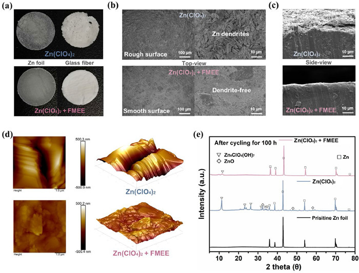
To further elucidate the role of the FMEE additive, the changes of Zn anodes were characterized after 100 h cycling in Zn||Zn symmetric cells. Fig. 2a displayed optical images of the Zn anodes and glass fiber separators cycled in Zn(ClO4)2 and Zn(ClO4)2 + FMEE electrolytes, respectively. In Zn(ClO4)2 electrolyte, the Zn anode showed a powdery surface of dark color without any metallic luster, and zinc deposits were observed on the glass fiber. This indicated that the rapid failure of the Zn||Zn(ClO4)2||Zn cell would be attributed to the formation of by-products on the Zn anode surface and the penetration of Zn dendrites through the separator. On the contrary, the Zn anode cycled in Zn(ClO4)2 + FMEE electrolyte exhibited a flat surface covered with a grayish-white solid film, and the glass fiber remained clean without any damage. Then, as shown in Fig. 2b, scanning electron microscopy (SEM) was employed to characterize the surface morphology of the Zn anodes. In Zn(ClO4)2 electrolyte, the deposited zinc protrusions were loosely piled up on the surface of the Zn anode, forming numerous uncontrolled Zn dendrites. In contrast, the surface of the Zn anode was flat and dense after cycling in Zn(ClO4)2 + FMEE electrolyte. Even after long-term cycling of 400 h at 1 mA/cm2, the growth of Zn dendrites was well suppressed, demonstrating excellent surface stability (Fig. S10 in Supporting information). Additionally, there were evident differences in the cross-sectional morphology of the Zn anodes (Fig. 2c). In Zn(ClO4)2 electrolyte, the Zn anode surface was uneven with irregularly formed Zn dendrites loosely adhered to the Zn anode. However, in Zn(ClO4)2 + FMEE electrolyte, a closely adhered and smooth protective film was observed on the surface, allowing the Zn anode to maintain its original integrity and smoothness. Atomic force microscopy (AFM) was used to observe the topography of the cycled Zn anode (Fig. 2d and Fig. S11 in Supporting information). In Zn(ClO4)2 electrolyte, the Zn anode surface became uneven and its roughness increased sharply, indicating the occurrence of serious Zn dendrite growth [43]. In sharp contrast, in Zn(ClO4)2 + FMEE electrolyte, minor protrusions were observed on the Zn anode, and the roughness was noticeably reduced. These results suggested that the presence of FMEE in the electrolyte suppressed Zn dendrites. Moreover, the X-ray powder diffraction (XRD) pattern of the Zn anode in Zn(ClO4)2 electrolyte revealed the presence of severe side reactions, as evidenced by the strong peaks of ZnO and Zn4ClO4(OH)7 (Fig. 2e) [44]. In contrast, these by-products were rare on the surface of the Zn anode in Zn(ClO4)2 + FMEE electrolyte, confirming that this approach can effectively mitigate the side reactions [45]. The improvement of the Zn anode in Zn(ClO4)2 + FMEE electrolyte could be attributed to the formation of an effective protective layer on the Zn anode surface.
Figure 2
Figure 2.
Characterizations of the Zn anodes after cycling for 100 h at 1 mA/cm2 and 1 mAh/cm2 in Zn(ClO4)2 and Zn(ClO4)2 + FMEE electrolytes. (a) Digital images of Zn anodes and glass fibers after cycling in two electrolytes. (b) Top-view SEM images and (c) side-view SEM images of Zn anodes after cycling in two electrolytes. (d) AFM images of Zn anodes after cycling in two electrolytes. (e) XRD pattern of Zn anodes after cycling in two electrolytes.
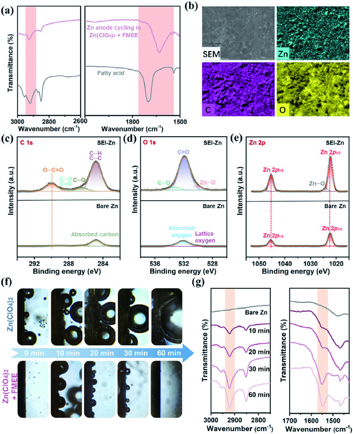
To reveal the composition of the grayish-white solid protective layer on the surface of the Zn anode, Fourier-transform infrared spectroscopy (FTIR), energy-dispersive X-ray spectroscopy (EDS), and X-ray photoelectron spectroscopy (XPS) analyses were conducted. For simplicity, the Zn anode with SEI is named as SEI-Zn, prepared from the Zn||Zn symmetric cell after cycling in Zn(ClO4)2 + FMEE electrolyte for 50 h at 1 mA/cm2 and 1 mAh/cm2. As shown in the FTIR spectra in Fig. 3a, the fatty acid exhibited two peaks at 2918 and 2850 cm−1 associated with the C−H stretching vibration, and a strong peak at 1700 cm−1 corresponding to the stretching vibration of carbonyl (C=O). These characteristic peaks were also observed in the FTIR spectra of SEI-Zn, while the redshift of C=O vibration peak to 1629 cm−1 is attributed to the complexation of C=O with Zn2+ to form fatty acid-zinc [21]. EDS analyses confirmed the uniform distribution of C and O elements on the surface of SEI-Zn (Fig. 3b). XPS analyses of bare Zn and SEI-Zn were further performed (Figs. 3c-e). The C 1s peak of SEI-Zn could be split into four peaks: the peaks at 284.8, 286.4, 288.2, and 290.0 eV corresponding to C−C, C−O, C=O, and COO− respectively. In contrast, the signals of C=O and COO− were not observed in the C 1s spectrum of bare Zn [46]. The O 1s spectrum of SEI-Zn exhibited signals at 531.9 and 533.2 eV, corresponding to the C=O and C−O groups of fatty acid, respectively, and the O 1s peak at 530.2 eV indicated the presence of polar Zn−O bonds. On the other hand, the peaks at 532.1 and 529.9 eV of bare Zn could be attributed to surface-adsorbed oxygen and lattice oxygen, respectively [21]. In addition, there were only Zn0 signals (Zn 2p1/2 and Zn 2p3/2) on the surface of bare Zn in the Zn 2p spectrum, while Zn−O signals appeared on the surface of SEI-Zn, indicating the presence of Zn−O coordination bonds. The above characterizations confirmed that the main component of SEI is fatty acid-zinc. As a side note, the FMEE in the electrolyte was not totally consumed after cycling, as verified by the 1H NMR spectrum of the residual substances in the cycled Zn||Zn symmetric cell (Fig. S12 in Supporting information). The unconsumed FMEE ensured an adequate reaction rate during SEI formation.
Figure 3
Figure 3.In situ formation mechanism of fatty acid-zinc SEI. (a) FTIR spectra of fatty acid powder and Zn anode after cycling in Zn(ClO4)2 + FMEE electrolyte for 50 h (SEI-Zn). (b) EDS mapping images of SEI-Zn. (c-e) XPS spectra of bare Zn and SEI-Zn. (f) Optical microscopy images were captured of Zn anodes during the deposition process at various time intervals in two different electrolytes within quartz electrochemical cells. (g) FTIR spectra of Zn anodes corresponding to different deposition time.
To understand the formation process of the SEI, we constructed Zn||Zn(ClO4)2||Zn and Zn||Zn(ClO4)2 + FMEE||Zn symmetric cells in the transparent quartz electrochemical cells and applied a current density of 1.0 mA/cm2 for Zn deposition (Fig. 3f) [47]. In the case of Zn(ClO4)2 electrolyte, bubbles were generated on both electrodes and became more pronounced with the increase of deposition time, indicating severe HER and Zn corrosion. In sharp contrast, small bubbles appeared on the electrode surface in the initial 10 min of deposition in Zn(ClO4)2 + FMEE electrolyte because of HER. Fortunately, as the deposition process progressed, the bubbles significantly reduced, showing the inhibition of HER [46]. There was negligible corrosion on the surface of the deposited Zn anode (Fig. S13 in Supporting information). The surface composition of the Zn anode in Zn(ClO4)2 + FMEE electrolyte at different deposition times was characterized through ex-situ IR spectroscopy. As shown in Fig. 3g, the fatty acid-zinc SEI formed on the surface of Zn anode after 10 min of deposition, and gradually stabilized over the next 30 min. This process demonstrated that the initial HER provided OH− for the subsequent in-situ formation of the fatty acid-zinc-based SEI.
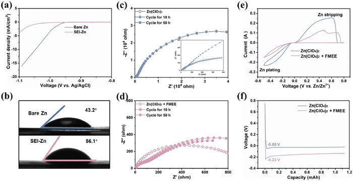
The specific Zn deposition behaviors in two electrolytes were investigated to assess the effectiveness of the in-situ SEI. As shown in the linear sweep voltammetry (LSV) curves in Fig. 4a, the current density was much lower for SEI-Zn compared to bare Zn across the entire voltage range, confirming effective suppression of HER on SEI-Zn [48]. Moreover, the SEI-Zn showed a higher contact angle of 56.1° compared to that of bare Zn (43.2°) (Fig. 4b). The more hydrophobic SEI could reduce the direct contact between H2O and the Zn surface, thereby reducing side reactions [21].
Figure 4
Figure 4.
The improvement in Zn deposition behaviors. (a) LSV curves of bare Zn and SEI-Zn tested at a scan rate of 5 mV/s. (b) Contact angles of the corresponding electrolytes on bare Zn and SEI-Zn. (c, d) EIS spectra of Zn||Zn symmetric cells with two electrolytes tested immediately after assembly and after cycling for 10 h/50 h. (e) CV curves showing Zn nucleation behavior on Cu cathodes and (f) initial nucleation overpotentials of Zn plating on Cu cathodes in Zn||Cu asymmetric cells in two electrolytes.
The long-term stability of SEI is critical for evaluating the effectiveness of Zn anode protection [40]. Electrochemical impedance spectroscopy (EIS) measurements were performed for the Zn||Zn symmetric cells cycled in two electrolytes. As shown in Fig. 4c and Table S1 (Supporting information), after 50 h of cycling, the charge transfer resistance (Rct) of the Zn||Zn symmetric cell in Zn(ClO4)2 electrolyte increased significantly, reaching an order of 104. This indicated a failure at the electrode-electrolyte interface, unable to transport ions normally. In contrast, as shown in Fig. 4d, after 10 h cycling of the Zn||Zn symmetric cell in Zn(ClO4)2 + FMEE electrolyte, the Rct showed a slight increase compared to the initial one, and a new semicircle appeared at high frequencies attributed the resistance of SEI (RSEI). In the subsequent cycles, the Rct and RSEI remained largely unchanged compared to those at 10 h of cycling, indicating long-term stability of the SEI. These results demonstrated that the SEI was formed in a spatially and temporally synchronized manner on the Zn anode surface during cycling, which effectively mitigated harmful side reactions and ensured excellent interface stability in Zn(ClO4)2 + FMEE electrolyte. Additionally, Figs. 4e and f revealed the nucleation overpotential in Zn||Cu asymmetric cells using two electrolytes. The deposition potential of the Zn||Cu asymmetric cell in Zn(ClO4)2 + FMEE electrolyte was more negative compared to Zn(ClO4)2 electrolyte. Furthermore, the initial nucleation overpotential increased from 0.05 V to 0.23 V when the current density was 2 mA/cm2. The larger nucleation overpotential indicated a reduced nucleation radius, facilitating the formation of a more uniform and smoother Zn deposition layer with smaller grain sizes, ultimately contributing to a dendrite-free Zn anode [49].
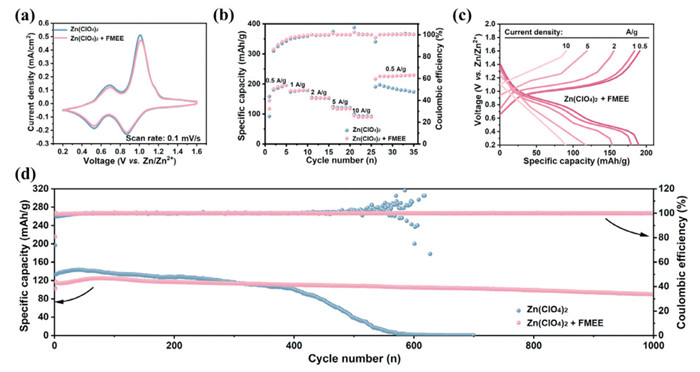
To validate the practical applications of this strategy, Zn-V2O5 full cells were electrochemically characterized. Using nanoscale V2O5 powder as cathode material, Zn||Zn(ClO4)2||V2O5 and Zn||Zn(ClO4)2 + FMEE||V2O5 full cells were assembled. The cyclic voltammetry (CV) curves of the cells in two electrolytes within the voltage window of 0.2–1.6 V at a scan rate of 0.1 mV/s are shown in Fig. 5a. Both CV curves exhibited two pairs of typical oxidation/reduction peaks, corresponding to the valence state changes of vanadium [50]. Furthermore, the similarity in oxidation/reduction potentials suggested that FMEE additive did not alter the redox reaction mechanism of V2O5. The similar Rct of the two full cells demonstrated that the reaction kinetics of the V2O5 cathode are close (Fig. S14 in Supporting information). As shown in Fig. 5b, the rate performance of the Zn-V2O5 cells in two electrolytes was also investigated. In Zn(ClO4)2 + FMEE electrolyte, high capacities of 189.6, 179.8, 153.5, 117.8, and 90.0 mAh/g were achieved at the current densities of 0.5, 1, 2, 5 and 10 A/g, respectively. In contrast, Zn-V2O5 cells without the additive exhibited comparable reversible capacities at the same current densities, measuring 185.8, 178.5, 152.8, 120.7, and 92.5 mAh/g. When the current density returned to 0.5 A/g, the cell with Zn(ClO4)2 + FMEE electrolyte immediately rebounded to a reversible capacity of 216.3 mAh/g and maintained preferable cycling stability, while the cell with Zn(ClO4)2 electrolyte showed lower and rapidly decaying capacities. The constant-current charge/discharge curves exhibited two distinct sloping discharge/charge curves for both cells, corresponding to the reversible redox processes, consistent with the CV curves (Fig. 5c). Long-term cycling performance of the full cells using two electrolytes was further investigated at a current density of 5 A/g (Fig. 5d). The Zn-V2O5 full cell using Zn(ClO4)2 electrolyte exhibited rapid capacity decay after 400 cycles, mainly attributed to the formation of Zn dendrite growth and side reactions. In sharp contrast, the cycling stability of the Zn-V2O5 cell in Zn(ClO4)2 + FMEE electrolyte demonstrated a significant improvement, maintaining a discharge capacity of 90.04 mAh/g after 1000 cycles, with a capacity retention of 76.8%. Thus, this effective strategy of in-situ SEI formation by adding FMEE also enhanced the electrochemical ability of ZIB full cells.
Figure 5
Figure 5.
The electrochemical performance of the Zn-V2O5 full cells. (a) CV curves of the Zn-V2O5 full cells using two electrolytes at a scan rate of 0.1 mV/s. (b) Rate performance of the Zn-V2O5 full cells using two electrolytes. (c) Charge/discharge curves of the Zn||Zn(ClO4)2 + FMEE||V2O5 full cell at different rates. (d) Cycling stability and CE of the Zn-V2O5 full cells using two electrolytes at a current density of 5 A/g.
In summary, to address critical interface issues of Zn anode, we propose an efficient approach for spatially-temporally synchronized constructing a stable electrode-electrolyte interface by leveraging the alkaline hydrolysis of ester groups in FMEE. This method enables the in-situ formation of a dense, stable, and highly conductive fatty acid-zinc SEI protective layer on the surface of the Zn anode in high-water-content electrolytes. The SEI promotes uniform Zn deposition, suppresses Zn dendrite growth, and mitigates the side reactions associated with H2O, thereby stabilizing the Zn-electrolyte interface. Benefiting from these improvements, Zn||Zn symmetric cell achieves long-term cycling stability, exceeding 2700 h, while Zn||Cu asymmetric cell demonstrates a high CE of 99.04%. Additionally, the Zn-V2O5 full cell using Zn(ClO4)2 + FMEE electrolyte exhibits good rate performance and significantly boosted cycling stability compared to that using Zn(ClO4)2 electrolyte. This study presents a novel in situ interface design approach to stabilizing Zn anode, with a focus on enhancing cycling performance and operational ease, thus providing a prospective avenue for practical high-performance ZIBs. Through rational design, this method holds potential for application in other aqueous metal-ion batteries susceptible to interface-related side reactions, thereby opening a pathway for the advancement of aqueous rechargeable energy storage applications.
Declaration of competing interest
The authors declare that they have no known competing financial interests or personal relationships that could have appeared to influence the work reported in this paper.
This work was supported by the National Natural Science Foundation of China (No. 22309211); the Guangdong Basic and Applied Basic Research Foundation (No. 2024A1515010158); the Guangzhou Science and Technology Programme (No. SL2023A04J01514); the Lanzhou Chengguan District Science and Technology Plan Project (No. 2022-rc-4).
Supplementary materials
Supplementary material associated with this article can be found, in the online version, at doi:10.1016/j.cclet.2024.110422.
Figure 1
Electrochemical performance of Zn anodes in Zn(ClO4)2 and Zn(ClO4)2 + FMEE electrolytes. (a) Diagram of Zn anode surface evolution and interfacial layer formation mechanism in two electrolytes. (b) Long-term constant current cycling performance of Zn||Zn symmetric cells using two electrolytes at 1 mA/cm2 and 1 mAh/cm2. Insets show magnified views of the voltage profiles. (c) Coulombic efficiency (CE) of Zn deposition/stripping in Zn||Cu asymmetric cells using two electrolytes at 2 mA/cm2 and 1 mAh/cm2. Insets show the corresponding voltage curves at different cycle numbers.
Figure 2
Characterizations of the Zn anodes after cycling for 100 h at 1 mA/cm2 and 1 mAh/cm2 in Zn(ClO4)2 and Zn(ClO4)2 + FMEE electrolytes. (a) Digital images of Zn anodes and glass fibers after cycling in two electrolytes. (b) Top-view SEM images and (c) side-view SEM images of Zn anodes after cycling in two electrolytes. (d) AFM images of Zn anodes after cycling in two electrolytes. (e) XRD pattern of Zn anodes after cycling in two electrolytes.
Figure 3In situ formation mechanism of fatty acid-zinc SEI. (a) FTIR spectra of fatty acid powder and Zn anode after cycling in Zn(ClO4)2 + FMEE electrolyte for 50 h (SEI-Zn). (b) EDS mapping images of SEI-Zn. (c-e) XPS spectra of bare Zn and SEI-Zn. (f) Optical microscopy images were captured of Zn anodes during the deposition process at various time intervals in two different electrolytes within quartz electrochemical cells. (g) FTIR spectra of Zn anodes corresponding to different deposition time.
Figure 4
The improvement in Zn deposition behaviors. (a) LSV curves of bare Zn and SEI-Zn tested at a scan rate of 5 mV/s. (b) Contact angles of the corresponding electrolytes on bare Zn and SEI-Zn. (c, d) EIS spectra of Zn||Zn symmetric cells with two electrolytes tested immediately after assembly and after cycling for 10 h/50 h. (e) CV curves showing Zn nucleation behavior on Cu cathodes and (f) initial nucleation overpotentials of Zn plating on Cu cathodes in Zn||Cu asymmetric cells in two electrolytes.
Figure 5
The electrochemical performance of the Zn-V2O5 full cells. (a) CV curves of the Zn-V2O5 full cells using two electrolytes at a scan rate of 0.1 mV/s. (b) Rate performance of the Zn-V2O5 full cells using two electrolytes. (c) Charge/discharge curves of the Zn||Zn(ClO4)2 + FMEE||V2O5 full cell at different rates. (d) Cycling stability and CE of the Zn-V2O5 full cells using two electrolytes at a current density of 5 A/g.

 DownLoad:

 下载:
下载:


 下载:
下载:
