Figure 1.
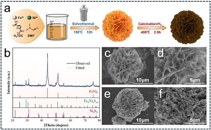
(a) The schematic diagram for the synthesis process of NiFe-MOF and FeNi3-S. (b) The XRD pattern of FeNi3-S. (c, d) SEM patterns of NiFe-MOF. (e, f) SEM patterns of FeNi3-S.
A MOF derived multi-phase FeNi3-S catalyst for efficient hydrogen storage in magnesium hydride
Linxin Zheng , Shuai Li , Liuting Zhang , Tao Zhong , Xiuzhen Wang , Ting Bian , Petr Senin , Ying Wu

Increased energy consumption and depletion of fossil fuel reserves pose a hazard to global energy security and the economy [1]. In comparison to fossil fuels, hydrogen stands out as a promising alternative on account of its sustainability and eco-friendliness, while its low volumetric density under standard conditions is the primary impediment to the storage and transportation of hydrogen [2,3]. Over the past few decades, hydrogen storage methods including compressed hydrogen storage, liquid hydrogen storage, cryo-compressed hydrogen storage and solid hydrogen storage have got a spectacular development [4]. In terms of safety and efficiency, solid hydrogen storage comes to the fore, fueling a surge in research of solid-state materials for hydrogen storage [5]. Among miscellaneous materials, MgH2 has been brought into sharp focus by its high volumetric (110 kg H2/m3) and gravimetric (7.6 wt% H2) capacities, fantastic reversibility, and abundant magnesium reserves. Nevertheless, the high thermodynamic stability (ΔH = 76 kJ/mol) and kinetic barrier (Ea = 160 kJ/mol), which bring about high-temperature desorption and sluggish hydrogen ab/de-sorption kinetics respectively, have hinder the practical application of MgH2 in the long run [6,7].
In recent years, researchers have developed the following strategies to address the challenges: nanosizing the Mg particles [8–10], alloying Mg particles with mental elements [11–13] and adding different catalysts into Mg/MgH2 hydrogen storage systems [14–16]. It has been proven that the addition of catalysts together with nanosized Mg particles via ball milling is the best bet to improve the performance of MgH2 in both thermodynamic and kinetic aspects [17,18]. Transition metals (TM), such as Ni [19,20], Fe [21,22], Ti [23,24], Co [25,26], V [27,28], along with their alloys/compounds (oxides, sulfide, halides, hydrides etc.), exhibit significant catalytic effects on the kinetics of MgH2. Some TMs like Ni and Co involve in the reaction and generate intermetallic hydrides of Mg2NiH4 and Mg2CoH5 in situ, thus serving as a “hydrogen pump” to accelerate the rates of hydrogen de/ab-sorption [29,30]. Apart from forming intermetallic hydrides, other TMs consist of Fe and Nb are also used as catalysts by virtue of the abundant d-orbital electron and excellent catalytic function [31]. Among all the TMs, M. Pozzo and his coworker have already proved that Ni and Fe (Ni ranks first) are the best possible choice to accelerate the kinetics of hydrogen absorption [32]. This work sheds light on the selection of transition metal elements. In addition, bimetallic catalysts have demonstrated higher efficiency than monometallic catalysts due to the synergistic effect [6,10]. Therefore, researchers have extensively investigated the effects of NiFe alloy catalysts on enhancing the hydrogen storage capabilities of MgH2. Ding et al. synthesized a core-shell structural Fe0.64Ni0.36@C composite and observed that the initial desorption temperature of MgH2-Fe0.64Ni0.36@C system was decreased to 250 ℃. Besides, 5.18 wt% H2 could be absorbed at 150 ℃ within 20 min [33]. Fu and co-workers found that NiFe@CNT decreased the onset desorption temperature of MgH2 to 225 ℃. Notably, the addition of NiFe@CNT significantly reduced the dehydrogenation activation energy of MgH2 to 49.7 kJ/mol [31]. Both of Ding and Fu had reported the synergistic effect between Fe and in-suit formed MgNi2/Mg2NiH4. Hence, the synergistic bimetallic catalysis of FeNi alloy has been confirmed to accelerate the reaction kinetics of MgH2 and effectively lower the energy barrier of the reaction.
Recent studies have indicated that transition metal sulfides (TMS) possess excellent catalytic activity, which has been confirmed in the fields of hydrogen and oxygen evolution reactions [34,35]. Based upon these findings, it is of great significance to reveal whether transition metal sulfides can enhance the hydrogen storage properties of MgH2. The research group led by Zhang had discovered that the addition of FeS2 and Fe3S4 contributed positively to the enhancement of hydrogen storage behavior in MgH2. They stated that the improved hydrogen storage capabilities of MgH2 were attributed to the synergistic catalytic action between the Fe and in-situ formed MgS [36,37]. Zeng et al. introduced a Ni3S2@C catalyst into MgH2 and found that the MgH2–Ni3S2@C-4 composite was able to absorb 5.68 wt% H2 upon dehydrogenation at 100 ℃ and release 6.35 wt% H2 upon rehydrogenation at 275 ℃ [38]. Additionally, Fu and colleagues had also applied ternary transition metal catalysts to MgH2. Under the synergistic catalysis of several active species, MgH2-FeNi2S4 composite uptook 4.02 wt% H2 at 100 ℃ for 1 h [16]. These finding underscored the potential of transition metal sulfides as additives for improving the performance of MgH2. Metal-organic frameworks (MOFs) have been proven to be ideal precursors for the preparation of metal sulfides [39]. MOF derived sulfides can be obtained by calcination in different atmospheres (such as air, H2, and Ar) and are more stable and conductive than primal MOFs [40]. In addition to retaining the original composition and characteristics of MOFs, MOF derived materials possess larger specific surface area and higher porosity and even hold better catalytic effect than primal MOFs [41].
It is noteworthy that bimetal and MOF derived sulfides are promising candidates for MgH2 hydrogen storage system. In a recent research, Zhang et al. designed defect-rich Ni0.67Fe0.33−MOF by a solvothermal method, providing more options for efficient OER systems [42]. Stimulated by the pioneering achievements, we synthesized NiFe-MOF and firstly designed FeNi3-S successfully to reveal whether NiFe-MOF and FeNi3-S could promote hydrogen absorption and desorption properties of Mg/MgH2 system. Through a systematic study of the de/resorption behavior of FeNi3-S doped MgH2 composites, we have demonstrated that FeNi3-S imparted a notable improvement to the hydrogen storage properties of MgH2. With the aid of structural and morphological characterizations, the synergistic catalytic mechanism of FeNi3-S was discussed in detail.
NiFe-MOFs were prepared by a reported solvothermal method [42] with a slight modification. Thiophene-2,5-dicarboxylic acid (H2TDC, Macklin, 98 %) and N,N-dimethylformamide (DMF, Macklim AR) were selected as organic ligand and solvent, while Ni(NO3)2⋅6H2O (Alfa Aesar, 98 %) and Fe(NO3)3⋅9H2O (Sinopharm Chemical Reagent Co., Ltd., AR) were used as nickel and iron sources. None of the chemicals used were further purified. The preparation process was as follows. 4 mmol Ni(NO3)2·6H2O, 4 mmol Fe(NO3)3⋅9H2O and 5 mmol H2TDC were added into a mixture of 60 mL DMF and deionized water. After complete dissolution, the blended solution was heated at 120 ℃ in a 100 mL Teflon-lined autoclave for 12 h. The sediment was collected by centrifugation, which was washed more than five times with a mixed 1:1 ratio of deionized water and ethanol solution to remove residual reactants. After a 12 h vacuum-drying period, the resulting brownish-yellow product was named as NiFe-MOF. The NiFe-MOF was then calcined at 400 ℃ for 2.5 h under a 4 MPa H2 atmosphere to obtain FeNi3-S.
MgH2 was synthesized from commercially available Mg (Aladdin, purity 99.99 %, 100–200 mesh) in our laboratory via several times of ball-milling and hydrogenation. Mg was hydrogenated at 380 ℃ under 7 MPa H2 pressure for 3 h. The samples were transferred into a stainless mill pot (Nanjing Chishun, 40:1 ball-to-powder weight ratio) and milled at a speed of 450 rpm for 5 h. After repeating the above steps twice, MgH2 powder was successfully fabricated. 100 mg NiFe-MOFs and 100 mg FeNi3-S were added into 900 mg as-prepared MgH2 powder respectively by ball milling at a speed of 400 rpm for 6 h. All operations were conducted in an argon-fille glovebox (MIKROUNA), where H2O and O2 levels all below 0.1 ppm.
The phase compositions of the samples were undertaken via X-ray diffraction (Smart Lab SE 6 kW) tests, scanning from 20° to 80° at a rate of 6°/min. The micromorphology of the sample was characterized by scanning electron microscope (SEM, Hitachi SU8600) and transmission electron microscopy (TEM, JEM-2100F). The corresponding energy dispersive X-ray spectroscopy (EDS) displayed the element distribution. A Pressure-Composition-Temperature (PCT) equipment had been self-established to research the hydrogen storage properties (more detailed explanation could be found in the supporting information). Before each experiment, 120–150 mg powders were transferred into a steel tube, which was specially designed for hydrogen storage performance tests in our lab. The non-isothermal dehydrogenation was conducted at a heating rate of 5 ℃/min from room temperature to 450 ℃, while the non-isothermal hydrogen absorption was 1 ℃/min. In isothermal experiments, the samples were performed at constant temperatures. The initial hydrogen pressure of absorption was 3.2 MPa, and that of dehydrogenation was lower than 0.001 MPa. For cyclic experiments, the composite was similarly hydrogenated at 3.0 MPa, dehydrogenated at 0.001 MPa, and repeated 20 times at 300 ℃.
The NiFe-MOF was synthesized via a self-assembly process under 120 ℃ for 12 h. The FeNi3-S materials were then fabricated by calcinating NiFe-MOF at 400 ℃ for 2.5 h under the H2 atmosphere. Fig. 1a shows the schematic diagram for the synthesis of the NiFe-MOF and FeNi3-S materials.
The phase compositions of NiFe-MOF and FeNi3-S were detected via XRD analysis. The XRD pattern of NiFe-MOF (Fig. S1 in Supporting information) matched well with the previous research of Zhang et al. [42], which implied successful synthesis of NiFe-MOF. The XRD spectrum of FeNi3-S was provided in Fig. 1b. Several sharp diffraction peaks could be perceived, indicating that the resultant FeNi3-S had a good crystal structure. Three distinct diffraction peaks located at approximately 44.07°, 51.34°, and 75.56° were consistent with the characteristic peaks of FeNi3. In addition to the prominent peaks corresponding to FeNi3, the XRD pattern also exhibited minor peaks indicative of the presence of Fe9Ni9S16 and Ni3S2, further describing the composition of the sample. The XRD result confirmed the formation of a multi-phase catalytic system consisting of FeNi3 alloys and two mental sulfides (Ni3S2 and Fe9Ni9S16). Thus, the hydrogen-annealed NiFe-MOF was labeled as FeNi3-S in this work.
Morphological and structural analysis of the NiFe-MOF and FeNi3-S material were carried out through SEM. Micron-sized NiFe-MOF (Figs. 1c and d) was corroborated as a nanoflower morphology and consisted of many petal-like nanosheets. The average thickness of these petal-like nanosheets was 20 nm. The magnified image is shown in the Figs. S2a and b (Supporting information). These nanosheets possessed uneven surface with many small particles decorated on it. After calcination, the matrix shape of the MOF did not collapse as shown in Figs. 1e and f. FeNi3-S had a nanoflower structure as well, with a host of macropores and mesopores formed on the petal-like surface. The nanosheets transformed into many irregular nanopores and nanoparticles (Figs. S2c and d in Supporting information). The shapes of these nanoparticles were primarily linear, with an average width of 0.041 µm. Additionally, larger flake-like particles and finer particles could also be observed. Irregular shapes and pores provided a larger specific surface area and shorter diffusion channels, endowing FeNi3-S with higher catalytic activity.
To compare the catalytic effect of the as-synthesized NiFe-MOF and FeNi3-S, non-isothermal dehydrogenation tests were implemented on pure MgH2, MgH2 + 10 wt% NiFe-MOF composite and MgH2 + 10 wt% FeNi3-S composite. The non-isothermal dehydrogenation processes were shown in Fig. 2a. Obviously, the doping of the NiFe-MOF and FeNi3-S catalyst significantly reduced the initial desorption temperature of MgH2. Pure MgH2 began to dehydrogenate at a high temperature of 325 ℃. The initial dehydrogenation temperature of NiFe-MOF dopped MgH2 was decreased to 227 ℃, while that of FeNi3-S modified MgH2 was further shifted to 202 ℃. The corresponding differential curves compared the peak dehydrogenation temperature of MgH2 dopped with NiFe-MOF and FeNi3-S. Specifically, MgH2 + 10 wt% FeNi3-S composite exhibited a peak dehydrogenation temperature of 307 ℃, while MgH2 + 10 wt% FeNi3-S composite showed a peak dehydrogenation temperature of 329 ℃.

The results above revealed that NiFe-MOF and FeNi3-S both had splendid influences on hydrogen desorption process of MgH2. Between the two doped systems, MgH2 + 10 wt% FeNi3-S composite exhibited superior dehydrogenation properties. Therefore, MgH2 + 10 wt% FeNi3-S composite was selected for subsequent kinetic investigations. It could also be observed from the curves that the hydrogen storage capacity inevitably decreased with the addition of the catalyst due to lower proportion of MgH2 in the composite. One the other hand, combined with sulfides in FeNi3-S, a small amount of Mg had been converted to MgS. This would be explained in detail in subsequent sections.
Fig. 2b displays the isothermal hydrogen desorption kinetic curves of the MgH2 + 10 wt% FeNi3-S composite at 250, 275, 300, and 325 ℃. Consistent with expectations, the desorption process performed swifter kinetics upon the elevation of the temperature. At 325 ℃, MgH2 + 10 wt% FeNi3-S composite could release 6.57 wt% H2 (fully dehydrogenated) within 1000 s. When the temperature reached 275 ℃, MgH2 + 10 wt% FeNi3-S composite still quickly liberated 6.30 wt% H2 within 1000 s. Furthermore, it was noted that at the comparatively lower temperature of 250 ℃, the same material was capable to desorb 3.04 wt% H2 within 1000 s. In the control experiments, as-prepared MgH2 exhibited a quite sluggish dehydriding rate (Fig. 2c). Undoped-MgH2 could only release 2.0 wt% H2 within 1000 s even at a high temperature of 335 ℃, which was 1.0 wt% less than MgH2 + 10 wt% FeNi3-S composite at a lower temperature of 250 ℃.
To delve deeper into the effect of FeNi3-S on the dehydriding reaction of MgH2, the apparent activation energy (Ea) for dehydrogenation was computed utilizing both the Johnson-Mehl-Avrami-Kolmogorov (JMAK) model and the Arrhenius equation. The formulation of the JMAK model was as follows:
|
|
(1) |
where α was the extent of the reaction, t denoted the reaction duration, n denoted the Avrami exponent, and k represented the rate constant. Thereafter, Ea was ensured using the Arrhenius equation:
|
|
(2) |
where k denoted the rate constant, T meant the isothermal hydrogen desorption temperature, A and R represented the pre-exponential factor and the gas constant respectively. In this work, the calculated values of Ea (Fig. 2d) in dehydrogenation reaction for MgH2 + 10 wt% FeNi3-S composite was 98.6 kJ/mol, achieving a 33 % reduction compared to that of pure MgH2 (146.3 kJ/mol). Manifestly, the incorporation of FeNi3-S nanoflowers significantly diminished the reaction barrier in the dehydrogenation process, thereby greatly enhancing the dehydrogenation kinetics of MgH2.
To analyze the performance of hydrogen absorption, non-isothermal and isothermal hydrogenation experiments were conducted for as-prepared MgH2 and MgH2 + 10 wt% FeNi3-S composite. Fig. 2e compares the non-isothermal hydrogen absorption results for as-prepared MgH2 and MgH2 + 10 wt% FeNi3-S composite. Evidently, the addition of the catalyst facilitated a substantial improvement in hydrogen absorption properties. The initial hydrogenation temperature of MgH2 was approximate 100 ℃. Noteworthy, the introduction of FeNi3-S resulted in a remarkable decrease to 35 ℃, which was 65 ℃ lower than the as-prepared MgH2. Fig. 2f presents the isothermal hydrogen absorption kinetic curves of the MgH2 + 10 wt% FeNi3-S composite at 100, 125, 150, and 175 ℃. It can be observed that the MgH2 + 10 wt% FeNi3-S composite reabsorbed 2.49 wt% H2 at 100 ℃ within 30 min. This was in stark contrast to MgH2 (Fig. 2g), which necessitated a significantly higher temperature of 200 ℃ to release an equivalent mass of hydrogen under identical experimental conditions. The above data illustrated that FeNi3-S doped MgH2 displayed superior hydrogen storage capability at low temperatures, along with rapid hydrogen absorption kinetics. To gain more profound understanding of the hydrogenation kinetics, Ea was calculated by using the JMAK model Eq. 1 and Arrhenius equation Eq. 2. Only 100, 125, and 150 ℃ were selected to calculate the activation energy since the rate of hydrogen absorption at 175 ℃ was excessively fast, which would result in a poor goodness of fit. As shown in Fig. 2h, the doping of FeNi3-S lowered the Ea value for hydrogen absorption of MgH2 from 81.3 kJ/mol to 43.3 kJ/mol, affirming the outstanding hydrogen absorption property of MgH2 + 10 wt% FeNi3-S composite.
The outstanding catalytic effect of FeNi3-S in the first de/absorption cycle prompted in-depth research on the cycling stability of FeNi3-S doped MgH2 composite, which was a critical indicator for the commercial viability of MgH2. Fig. 3a details the fluctuations in hydrogen storage capacity and presents several typical cycles over the first 20 isothermal consecutive dehydrogenation and hydrogenation cycles. After 20 cycles, the MgH2 + 10 wt% FeNi3-S composite maintained desorption and absorption content at 6.2 wt% and 6.3 wt%, and the retention ratio was 94.2 % and 96.0 % respectively. In addition, the curves depicted that the MgH2 + 10 wt% FeNi3-S composite was able to complete hydrogen release and uptake reaction within 10 min during all the 20 cycles. In conclusion, the MgH2 + 10 wt% FeNi3-S composite manifested an exceptional cycling performance with stable retention both in capacity and kinetics, indicating that FeNi3-S served as a highly potent and reliable catalyst for MgH2 to enhance the cycling life of MgH2. Notably, the hydrogen capacity of the composite exhibited a slight decrease but then rebounded, potentially attributed to the formation and decomposition of magnesium oxide layer on MgH2/Mg [43]. In addition, it was observed that the kinetics of dehydrogenation improved from the first cycle to the latter (Fig. 3b), which had been studied in our former studies [44]. After several cycle activation, MgH2 + 10 wt% FeNi3-S composite was activated, making it more amenable to hydrogen de/absorption. The FeNi3, Fe and MgS generated during the activation could significantly improve the kinetics of MgH2. Analyses suggested that the MgH2 + 10 wt% FeNi3-S composite was supposed to undergo several activation cycles to improve its initial hydrogen storage performance and to ensure its reliability and stability for long-term use.
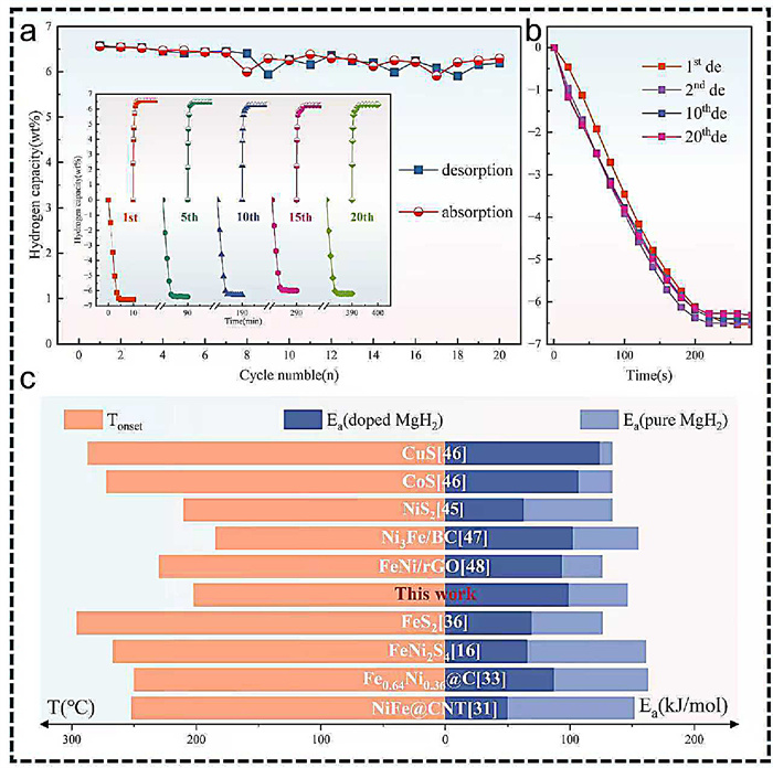
Based on the discussion of experimental results and theoretical calculation, it was reasonable to conclude that FeNi3-S efficiently modified the kinetic and thermodynamic properties of MgH2. Fig. 3c compiled some current studies on FeNi alloy and FeNi sulfide added in MgH2, which provided solid evidence for the superior hydrogen storage performances of the MgH2 + 10 wt% FeNi3-S composite [16,31,33,36,45–48].
To comprehensively elucidate the catalytic mechanism of FeNi3-S, relevant characterizations were conducted to ascertain the phase composition and microstructure of MgH2 + 10 wt% FeNi3-S composite under diverse states. Fig. 4a is the XRD spectrum of the MgH2 + 10 wt% FeNi3-S composite after ball milling, hydrogenation, dehydrogenation and 20 cycles. Diffraction peaks of MgH2 and FeNi3-S were detected in the ball milled state, but other phases of FeNi3-S were almost undetectable due to their low concentration. It suggested that no chemical transformation occurred during the ball milling process. The observed broadening of the XRD peaks implied that the crystallite size of MgH2 and FeNi3-S had been significantly reduced after ball milling. Mg and MgH2 were the main phase in de/re-hydrogenated states respectively. After dehydrogenation, FeNi3-S had been decomposed. MgH2 was converted into Mg, along with the in-situ emergence of several new phases including Mg2Ni, MgS, and Fe. The phase transformation of MgH2 + 10 wt% FeNi3-S composite in dehydrogenation could be outlined below:
|
|
(3) |
|
|
(4) |
|
|
(5) |
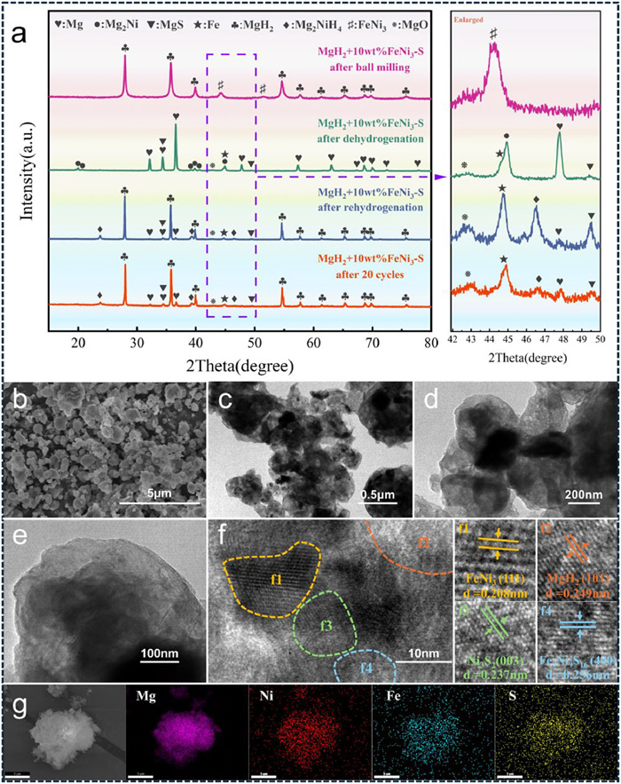
Compared with the ball-milled state, the XRD patterns of the MgH2 + 10 wt% FeNi3-S composite exhibited increased intensity and sharpness after de/re-hydrogenation. This enhancement could be attributed to the disappearance of lattice distortions and crystal defects, which were initially introduced during the ball milling process and subsequently mitigated during heating and hydrogenation [45]. The existence of Mg phase in rehydrogenated state was probably due to the partial hydrogenation caused by insufficient hydriding time. After 20 cycles, the feature diffraction peaks of Mg2NiH4, MgS and Fe were observed. Additionally, the diffraction peaks located at approximately 43° and 62° belonged to MgO. The formation of MgO was potentially attributable to the reaction between Mg particles and residual oxygen that was unavoidably introduced into the system during 20 cycles. Fortunately, the surface oxide layer gradually disintegrated with the ongoing cycling [43], contributing to the recovery of hydrogen storage capacity which correlated with the observed trend in hydrogen capacity curve (Fig. 3a). Characteristic peaks for Mg were also observed. This could be attributed to that Mg particles were prone to agglomeration and growth in the continuous cycles of hydrogenation and dehydrogenation [21], which led to the internal Mg being unable to react with H2 and form MgH2. Thus, the hydrogen content gradually declined as the cycles progress.
SEM, TEM, HRTEM and EDS mapping were carried out to further discover the microstructure of ball-milled MgH2 + 10 wt% FeNi3-S composite. After ball milling, the MgH2 and FeNi3-S were ground into many irregular fragments that were stacked upon one another (Fig. 4b). Figs. 4c–e depicted that FeNi3-S particles were inlaid on the surface of MgH2. Both MgH2 and FeNi3-S particles exhibited a relatively small size. HRTEM patterns in Fig. 4f confirmed the existence of MgH2 (101), FeNi3 (111), Ni3S2 (003) and Fe9Ni9S16 (400) planes according to the lattice fringe spacings. As a supplementary argument to the XRD pattern, HRTEM images reaffirmed that FeNi3-S did not undergo any chemical transformation during the ball milling process. Different phases of FeNi3-S intimately connected thus offering a multitude of boundaries and interfaces. EDS mapping images (Fig. 4g) revealed a uniform distribution of nickel, iron, and sulfur elements throughout the material. The uniform distribution of FeNi3-S stemmed from the unique carbon skeleton inherited from NiFe-MOF.
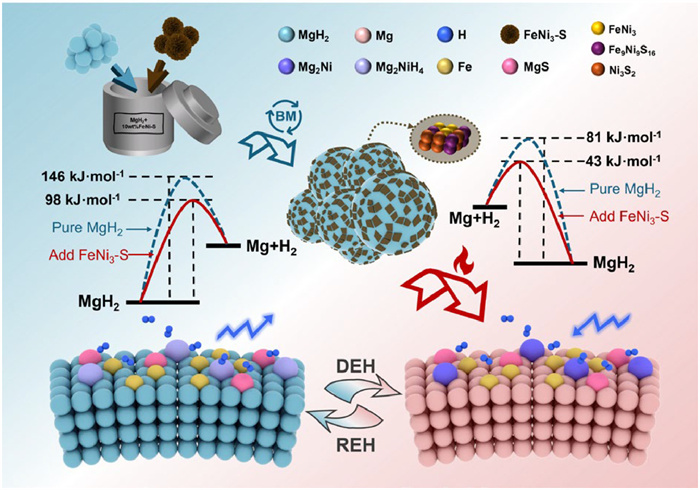
Based on the characterization results presented above, the catalytic mechanism can be summarized as follows (Fig. 5): (1) FeNi3-S was a MOF derived multi-phase catalyst composed of nickel-iron alloy and nickel-iron sulfide. The special nanoflower morphology, replete with an array of irregular nanopores, was instrumental in facilitating shorter diffusion pathways and the exposure of numerous active sites. This intricate architecture endowed FeNi3-S with remarkable catalytic performance. (2) After ball milling, the nanoflower-like structure fragmented into a variety of nanoparticle, homogeneously dispersing across the surface of MgH2. During the heating and the first dehydrogenation, FeNi3-S reacted with MgH2 and formed multi-phase catalysts in suit. Henceforth, the Mg/Mg2Ni + Fe/MgS and MgH2/Mg2NiH4 + Fe/MgS hydrogen storage systems had been successfully developed. The multifaceted interface facilitated the dissociation and recombination of H molecules by offering expanded active sites and diffusion pathways, thus improving the de/rehydrogenation properties of MgH2/Mg. Our recent research had proven that the enthalpy of formation for the Mg2Ni/Mg2NiH4 was lower than that of the Mg/MgH2 [49]. Hence, Mg2Ni/Mg2NiH4 altered the original reaction pathway, reducing the theoretical energy required for hydrogen desorption and absorption. In brief, Mg2Ni/Mg2NiH4 could de/absorb hydrogen more easily and rapidly than the Mg/MgH2 system, which had been previously studied and was referred to as “hydrogen pump” [19,20]. Besides, both Fe and MgS were consistently stable within the reaction system, functioning effectively as “hydrogen diffusion channel” to expedite hydrogen migration. Interestingly, Zhang et al. had experimentally verified that the co-catalytic impacts of Fe and MgS outperformed the individual catalytic effect when Fe or MgS was added separately [37]. Thereby, the synergistic catalytic effect of Mg2Ni/Mg2NiH4, along with Fe and MgS markedly boosted the hydrogen storage properties of Mg/MgH2 system. (3) The carbon skeleton, inherited from NiFe-MOF to FeNi3-S, played a pivotal role in preventing the agglomeration and growth of MgH2 throughout the cyclic processes, thereby effectively improving the cycle performance.
In this study, MOF-derived nanoflower-like FeNi3-S was successfully designed by the process of solvothermal and calcination, which was proven effective in improving the hydrogen storage properties of MgH2. The initial dehydrogenation temperature of MgH2 + 10 wt% FeNi3-S composite was 202 ℃, which was 123 ℃ lower than that of MgH2. At 250 ℃ and 325 ℃, MgH2 + 10 wt% FeNi3-S released 3.04 wt% H2 and 6.57 wt% H2 (fully dehydrogenated) within 1000 s. Surprisingly, MgH2 + 10 wt% FeNi3-S composite began to rehydrogenate at room temperature and rapidly absorb 2.49 wt% H2 within 30 min at 100 ℃. Based on the activation energy fitting calculations, the addition of FeNi3-S enhanced the de/resorption kinetics of MgH2 at low temperatures (Ea = 98.6 kJ/mol and 43.3 kJ/mol respectively). Furthermore, multi-phase synergistic catalytic effect was further proposed. The fast kinetics at low temperatures of MgH2 + 10 wt% FeNi3-S composite was owning to the in-situ formed Mg/Mg2Ni + Fe/MgS and MgH2/Mg2NiH4 + Fe/MgS hydrogen storage systems. The multi-phase synergistic catalytic effect between hydrogen pump (Mg2Ni/Mg2NiH4) and active sites provided by Fe/MgS greatly improved the hydrogen storage property of MgH2. In a summary, the combination between transition metal alloys (TMAs) and transition metal sulfides (TMSs) showed impressive catalytic effect on the de/resorption processes of MgH2, which opened up new avenues and provided fresh insights into overcoming the obstacles in Mg-based hydrogen storage. The results of the study were also useful for predicting the products of MOFs after calcination.
The authors declare that they have no known competing financial interests or personal relationships that could have appeared to influence the work reported in this paper.
Linxin Zheng: Writing – original draft, Investigation. Shuai Li: Writing – original draft, Methodology. Liuting Zhang: Writing – review & editing. Tao Zhong: Validation, Formal analysis. Xiuzhen Wang: Supervision, Funding acquisition. Ting Bian: Funding acquisition. Petr Senin: Supervision. Ying Wu: Supervision, Funding acquisition.
This work was supported by the National Key R&D Program of China (No. 2022YFB3803703), the National Natural Science Foundation of China (Nos. 52071141, 52271212, 52201250, 51771056, 22305104), the Natural Science Foundation of Jiangsu Province (No. BK20210893) and the Ministry of Science and Technology of the People's Republic of China (No. G2023014022L).
Supplementary material associated with this article can be found, in the online version, at doi:
J.O. Abe, A.P.I. Popoola, E. Ajenifuja, et al., Int. J. Hydrog. Energy 44 (2019) 15072–15086.
M.R. Usman, Renew. Sustain. Energy Rev. 167 (2022) 112743.
E.H. Abdechafik, H.A. Ousaleh, S. Mehmood, et al., Int. J. Hydrog. Energy 52 (2024) 1182–1193.
O. Faye, J. Szpunar, U. Eduok, Int. J. Hydrog. Energy 47 (2022) 13771–13802.
Y. Wang, Y. Xue, A. Züttel, Chem. Soc. Rev. 53 (2024) 972–1003. doi: 10.1039/d3cs00706e
X. Zhang, Y. Liu, X. Zhang, et al., Mater. Today Nano 9 (2020) 100064.
L. Ren, Y. Li, N. Zhang, et al., Nano Micro Lett. 15 (2023) 93.
C. Zhou, Y. Peng, Q. Zhang, J. Mater. Sci. Technol. 50 (2020) 178–183.
Y. Shang, C. Pistidda, G. Gizer, et al., J. Magn. Alloy. 9 (2021) 1837–1860.
V.V. Berezovets, R.V. Denys, I.Y. Zavaliy, et al., Int. J. Hydrog. Energy 47 (2022) 7289–7298.
Y. Zhang, G. Wu, J. Gu, et al., Rare Met. 43 (2024) 3260–3272. doi: 10.1007/s12598-024-02627-7
J. Zhang, X. Ding, R. Chen, et al., J. Power Sources 548 (2022) 232037.
Y. Fu, Z. Ding, S. Ren, et al., Int. J. Hydrog. Energy 45 (2020) 28154–28162.
H. Huang, T. Xu, J. Chen, et al., Chem. Eng. J. 483 (2024) 149434.
S. Li, L. Zhang, F. Wu, et al., Chin. Chem. Lett. 36 (2025) 109566.
Y. Fu, L. Zhang, Y. Li, et al., J. Magn. Alloys. 11 (2023) 2927–2938.
X. Xie, B. Zhang, H. Kimura, et al., Chem. Eng. J. 464 (2023) 142630.
N.S. Norberg, T.S. Arthur, S.J. Fredrick, et al., J. Am. Chem. Soc. 133 (2011) 10679–10681. doi: 10.1021/ja201791y
X. Li, Y. Fu, Y. Xie, et al., Int. J. Hydrog. Energy 46 (2021) 33186–33196.
X. Yang, Q. Hou, L. Yu, et al., Dalton Trans. 50 (2021) 1797–1807. doi: 10.1039/d0dt03627g
M. Song, L. Zhang, Z. Yao, et al., Inorg. Chem. Front. 9 (2022) 3874–3884. doi: 10.1039/d2qi00863g
P.K. Soni, A. Bhatnagar, M.A. Shaz, Int. J. Hydrogen Energy 48 (2023) 17970–17982.
D. Pukazhselvan, N. Nasani, P. Correia, et al., J. Power Sources 362 (2017) 174–183.
D. Pukazhselvan, K.S. Sandhya, D. Ramasamy, et al., ChemPhysChem 21 (2020) 1195–1201. doi: 10.1002/cphc.202000031
B. Liu, B. Zhang, X. Chen, et al., Mater. Today Nano 17 (2022) 100168.
L. Li, G. Jiang, H. Tian, et al., Int. J. Hydrog. Energy 42 (2017) 28464–28472.
Y. Meng, J. Zhang, S. Ju, et al., J. Mater. Chem. A 11 (2023) 9762–9771. doi: 10.1039/d3ta01029e
Z. Wang, Z. Ren, N. Jian, et al., J. Mater. Chem. A 6 (2018) 16177–16185. doi: 10.1039/c8ta05437a
S. Guo, Z. Yu, Y. Li, et al., J. Alloy. Compd. 976 (2024) 173035.
L. Zhang, H. Yu, Z. Lu, et al. Chin. J. Chem. Eng. 43 (2022) 343–352.
Y. Fu, Z. Yu, S. Guo, et al., Chem. Eng. J. 458 (2023) 141337.
M. Pozzo, D. Alfè, Int. J. Hydrog. Energy 34 (2009) 1922–1930.
Z. Ding, Y. Fu, L. Zhang, et al., J. Alloy. Compd. 843 (2020) 156035.
W. He, F. Wang, Y. Gao, et al., Sustain. Energy Fuels 6 (2022) 3852–3857. doi: 10.1039/d2se00886f
J. Mei, Y. Deng, X. Cheng, et al., Chin. Chem. Lett. 35 (2024) 108900.
W. Zhang, G. Xu, Y. Cheng, et al., Dalton Trans. 47 (2018) 5217–5225. doi: 10.1039/c7dt04665k
W. Zhang, Y. Cheng, D. Han, et al., Energy 93 (2015) 625–630.
L. Zeng, Z. Lan, B. Li, et al., J. Magn. Alloy. 10 (2022) 3628–3640.
D. Zhou, K. Cui, Z. Zhou, et al., Int. J. Hydrog. Energy 46 (2021) 34369–34380.
Y. Qian, F. Zhang, S. Zhao, et al., Nano Energy 111 (2023) 108415.
Y. Chen, R. Zhang, L. Jiao, et al., Coord. Chem. Rev. 362 (2018) 1–23.
S. Zhang, Z. Huang, T.T. Isimjan, et al., Appl. Catal. B Environ. 343 (2024) 123448.
L. Ren, Y. Li, Z. Li, et al., Nano Micro Lett. 16 (2024) 160.
L. Zhang, L. Ji, Z. Yao, et al., Int. J. Hydrog. Energy 44 (2019) 21955–21964.
P. Wang, Z. Wang, Z. Tian, et al., Renew. Energy 160 (2020) 409–417.
P. Wang, Z. Tian, Z. Wang, et al., Int. J. Hydrog. Energy 46 (2021) 27107-27118.
Q. Hou, J. Zhang, Z. Zheng, et al., Dalton Trans. 51 (2022) 14960-14969. doi: 10.1039/d2dt02425j
L. Ji, L. Zhang, X. Yang, et al., Dalton Trans. 49 (2020) 4146-4154. doi: 10.1039/d0dt00230e
T. Zhong, T. Xu, L. Zhang, et al., J. Magn. Alloy. 13 (2025) 148-160.

Figure 1 (a) The schematic diagram for the synthesis process of NiFe-MOF and FeNi3-S. (b) The XRD pattern of FeNi3-S. (c, d) SEM patterns of NiFe-MOF. (e, f) SEM patterns of FeNi3-S.

Figure 2 (a) Non-isothermal dehydrogenation curves of MgH2 + 10 wt% (NiFe-MOF/FeNi3-S) composites and the corresponding differential curves. (b) Isothermal dehydrogenation curves of MgH2 + 10 wt% FeNi3-S composites at 250, 275, 300 and 325 ℃. (c) Isothermal dehydrogenation curves of MgH2 at 335, 350, 365 and 380 ℃. (d) Fitted Arrhenius curves of MgH2 and MgH2 + 10 wt% FeNi3-S composites. (e) Non-isothermal hydrogenation curves of MgH2 + 10 wt% (NiFe-MOF/FeNi3-S) composites. (f) Isothermal hydrogenation curves of MgH2 + 10 wt% FeNi3-S composites at 100, 125, 150 and 175 ℃. (g) Isothermal hydrogenation curves of MgH2 at 200, 215, 230 and 245 ℃. (h) Fitted Arrhenius curves of MgH2 and MgH2 + 10 wt% FeNi3-S composites.

Figure 3 (a) Dehydrogenation and rehydrogenation cycles of MgH2 + 10 wt% FeNi3-S composites at 300 ℃ (the inset figure is representative dehydrogenation and rehydrogenation cycles). (b) Comparisons of different dehydrogenation curves during the 20 cycles. (c) Current studies on FeNi alloy and FeNi sulfide catalysts for MgH2 [16,31,33,36,45–48].

Figure 4 (a) The XRD patterns of MgH2 + 10 wt% FeNi3-S composites after ball-milling, de/rehydrogenation and 20 cycles. (b) SEM pattern of the MgH2 + 10 wt% FeNi3-S composite. (c–e) TEM patterns of MgH2 + 10 wt% FeNi3-S composites. (f) HRTEM patterns of the MgH2 + 10 wt% FeNi3-S composite. (g) EDS mapping of the MgH2 + 10 wt% FeNi3-S composite.

 扫一扫看文章

扫一扫关注我们
 DownLoad:
 下载:
下载:

 下载:
下载: