Figure 1.
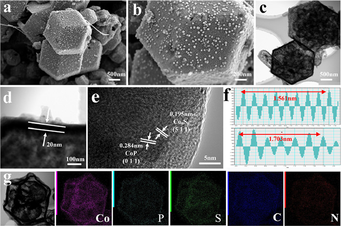
(a, b) SEM images, (c, d) TEM images, (e, f) HRTEM images, (g) element mapping images of Co9S8/CoP@NPSC.
Multiple yolks-shell cobalt phosphosulfide nanocrystals encapsulating into rich heteroatoms co-doped carbon frameworks for advanced sodium/potassium ion batteries
Yining Li , Shimei Wu , Lantao Chen , Haosen Fan , Yufei Zhang , Lingxing Zeng

The large consumption of electronic devices and the rapid evolution of electric vehicles have led to a dramatic increase in the demand for lithium resources in lithium-ion batteries (LIBs) [1-3]. However, the shortage and uneven distribution of lithium resources greatly impede the further development of LIBs. The exploitation of lower-cost and rich reserves metals based energy storage systems such as Na+/K+/Zn2+ batteries have been widely studied and developed as the potential substitutes for LIBs [4-6]. Nevertheless, the excessively large radius of Na+/K+ leads to a severe change in the volume of the active material during the reaction, which increases the odds of structural collapse leading to an adverse effect on the cycling stability and power density of the cell [7-9]. Thus, the exploitation of high-electrochemical storage activity and high cycling stability is a critical step in the commercialization and maturation of sodium-ion/potassium-ion batteries (SIBs/PIBs).
Transition metal sulfides (TMSs) and transition metal phosphides (TMPs) are well recognized as ideal anode materials because of their theoretically relatively stable capacity as well as abundant redox active sites [10]. TMSs, especially cobalt sulfides have been widely reported for their low cost, good electrical conductivity, and high thermal stability. For example, Hua et al. fabricated Co9S8@C nanosheets by solvothermal and vacuum high-temperature calcination methods, sustaining a high specific capacitance of 595 mAh/g (at 0.2 A/g after 160 cycles) [11]; Wang et al. prepared Co9S8 microcubes and microspheres by ion-exchange method, presenting good cycling stability (specific capacitance of 370 mAh/g at 1 C after 300 cycles). Meanwhile, cheap and abundant TMPs among CoP have captured attention due to their unique metal-like physicochemical behavior. For example, Huang et al. through polymerization and in situ phosphorylation of polydopamine (PDA) on ZIF-67, which held a compelling specific capacity of 223 mAh/g (at 0.5 C after 700 cycles) [12]; Jiang et al. synthesized CoP/NC@rGO composites showcasing long cycle stability up to 2800 cycles (177 mAh/g at 1 A/g) [13]. Nonetheless, the dramatic volume expansion of TMSs and TMPs hinders electron migration and affects electronic conductivity, resulting in poor redox kinetics during cyclic charging and discharging. At this point, the strategy of phosphorus sulfides was proposed, where the synergistic effect of sulfides and phosphides enhances the structural stability and prolongs the cycle life. For example, Meng et al. developed CoP/Co9S8 heterostructures as electrocatalysts for high-performance overall water decomposition [14]. The synergistic interaction between Co9S8 and CoP is beneficial for batteries to exhibit excellent electrochemical performance, however, little research has been done on this issue.
The porous crystalline material zeolitic imidazolate frameworks (ZIF-67) are a type of metal-organic framework (MOF) material with unique properties such as tunable composition and good stability. ZIF-67 can be used as a precursor to prepare cobalt-containing carbon nanotubes, porous carbon, or carbon composites by pyrolysis, coating, or carbonization, etc., which can be applied to batteries, electrocatalysis, and other fields [15-17]. Nowadays, heteroatom doping not only induces strong interactions between carbon and sodium/potassium to promote the insertion of sodium/potassium ions but also increases the spacing of the carbon layers so that sodium/potassium ions can migrate more easily, which is regarded as an effective method to improve the energy storage of carbon materials [18, 19]. For example, Wu et al. successfully synthesized N, P, and S triple-doped hexapodal carbon H-Co@NPSC using ZIF-67 hexapod as self-template. The defects created in the N, P, and S-doped carbon materials with various heteroatoms can provide more active sites and increase the specific surface area of the materials, which also helps to improve the electrochemical conductivity of the materials. In comparison with the undoped H-Co, the energy storage performance of H-Co@NPSC is significantly improved, and its reversible capacity was still maintained at 311.1 mAh/g (1 A/g) after 450 cycles [20]. Hence, the hetero-atoms co-doped carbon materials can greatly contribute to the battery properties and finding suitable heteroatom doping carbon materials for advanced electrode materials remains a big challenge.
Herein, multiple yolks-shell cobalt phosphosulfide nanocrystals confining into a multiple heterogeneous atoms doped carbon frameworks were successfully synthesized by annealing the core-shell ZIF-67@PZS intermediate, which was prepared from coating a polymer layer on the surface of ZIF-67. The obtained dodecahedral yolk-shell Co9S8/CoP@NPSC presents great application potential in the anode materials of SIBs and PIBs. Firstly, N, P, S doping increases the interlayer spacing of carbon layers, which promotes the convenient Na+/K+ transport. Secondly, the stable dodecahedral yolk-shell heterogeneous structure effectively prevents the aggregation of inner shell materials and relieves the large volume change during the charging/discharging processes. Finally, the synergistic effect of Co9S8 and CoP is integrated with the advantages of metal phosphides and sulfides to further improve the electrochemical performance. Based on the above advantages, Co9S8/CoP@NPSC provides excellent structural durability as an anode material. The specific capacity is maintained at 360.47 mAh/g (at 1 A/g after 300 cycles) in SIBs and 110 mAh/g (at 1 A/g after 500 cycles) in PIBs. This opens up new ideas for the use of transition metal phosphorus sulfide materials in SIBs and PIBs.
The schematic illustration for the preparation of multiple yolks-shell structure cobalt phosphosulfide (Co9S8/CoP@NPSC) is shown in Fig. S1 (Supporting information). Firstly, dodecahedral ZIF-67 MOF was prepared from a simple coprecipitation reaction by using Co2+ as metal centers and 2-methylimidazole as organic ligand. Then a polymer layer was grown on the surface of ZIF-67 to form core-shell structure monomers via in-situ polymerization of phosphonitrilic chloride trimer (HCCP) and 4, 4′-sulfonyldiphenol (BPS). At last, after the high temperature annealing and phosphorization/sulfidation processes, yolk-shell structure cobalt phosphosulfide Co9S8/CoP@NPSC was obtained due to the different decomposition rates of ZF-67 and polymer coating. The polymer coating derived N, P, S co-doped carbon frameworks form the external carbon shell, in which the cobalt phosphosulfide multiple yolks were encapsulated into the internal part of the dodecahedron.
The XRD pattern of Co9S8/CoP@NPSC was presented in Fig. S2 (Supporting information)), all of the diffraction peaks are well matched with the standard cards of Co9S8 (PDF #19-0364) and CoP (PDF #29-0497), indicating of the high crystallinity and high purity of the synthesized product. The XRD patterns of Co9S8@NPSC and CoP@NPSC contrast samples are shown in Figs. S3 and S4 (Supporting information)). ZIF-67 presents a dodecahedral structure with the smooth surface and the size of about 700 nm (Figs. S2b and c). The morphology of ZIF-67@NPSC is shown in Figs. S2d and e. We can see that the surface of ZIF-67@NPSC produces a layer of organic carbon containing three heteroatoms, N, P, and S, with little variation in size. The morphology of Co9S8/CoP@NPSC after annealing and phosphorus vulcanization is shown in Figs. S2f and g, most of the dodecahedral structures were well maintained and did not collapse after carbonization and phosphorization/sulfidation processes. The stable dodecahedral structure is conducive to keeping the structure stability of electrode materials during the repeated charge/discharge processes.
Figs. 1a and b show the SEM images of Co9S8/CoP@NPSC, the particles on the surface are the decomposition of the material into nanoparticles due to the high temperature during phosphorus vulcanization. The TEM image is shown in Fig. 1c, its morphology corresponds to the SEM image, which can see the dodecahedral structure of the yolk-shell. The yolk-shell structure presents a special core@void@shell configuration, while the multinucleated yolk-shell structure consists of a monoshell matrix and multinucleated particles with large voids to regulate volume expansion. The different components remain relatively independent, and the unique cavity structure between the yolk and shell around the particles can effectively inhibit the volume change. During the high-temperature annealing operation, the interior of the dodecahedron (Co9S8/CoP) starts to shrink with the gradual increase of the annealing temperature, and the yolk-shell structure is finally formed. In the unique core-shell heterostructure, the heterogeneous interface is in the interior of the material, thus presenting a firm built-in electric field direction from the outer layer to the inner layer with excellent structural durability [21]. The surface of ZIF-67@NPSC was covered by a layer of N, P, S doped carbon frameworks with a length of about 20 nm after polymerization and phase transformation (Fig. 1d). The HRTEM images of Co9S8/CoP@NPSC are depicted in Figs. 1e and f The lattice fringes on the (511) face of Co9S8 and the (011) face of CoP are 0.195 nm and 0.284 nm, respectively. The EDS images show the existence of the five elements (Co, P, S, N, and C) in the Co9S8/CoP@NPSC as shown in Fig. 1g. It can be noticed that the five elements are uniformly distributed into the dodecahedral structure, which also indicates that the uniform distribution of Co9S8 and CoP nanocrystals in the dodecahedron.
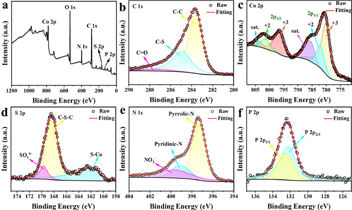
The total spectrum revealed the presence of Co, P, S, C, and N elements in the sensor (Fig. 2a). Besides this, the element O is also present, which may be due to the formation of CoO after the sample is exposed to air and absorbs oxygen. Fig. 2b displays three peaks of C 1s at 287.58, 284.88, and 283.58 eV attributed to C-N/O, C-S/P, and C-C, respectively [22]. The Co 2p in Fig. 2c includes six peaks situated at 804.08, 801.68, 796.78, 786.08, 782.28, and 780.28 eV, where the peaks at 796.78 and 780.28 eV belong to the 2p3/2 and 2p1/2 of Co3+, respectively, and the peaks at 801.68 and 782.28 eV were corresponding to 2p3/2 and 2p1/2 of Co2+, respectively. Three peaks of S 2p, 169.68, 168.28, and 161.68 eV pointing to SOx n−, C-S-C, and S-Co, respectively (Fig. 2d), indicating the establishment of S-doped carbon [20]. Three peaks of N 1s are shown in Fig. 2e, 399.68, 399.18, and 397.38 eV correspond to NO2 −, pyridine-N, and pyrrole-N, respectively, indicating the formation of N-doped material in the composite. In Fig. 2f, 132.58 and 132.18 eV point to P 2p1/2 and P 2p3/2, respectively, which are related to P2− in CoP, indicating the formation of metal phosphide in the composite [23].
The electrochemical performance of Co9S8/CoP@NPSC for SIBs is shown in Fig. 3. Fig. 3a, Figs. S5 and S6 (Supporting information) show cyclic voltammetry (CV) curves for Co9S8/CoP@NPSC, Co9S8 @NPSC, CoP@NPSC for the first three cycles at a voltage range of 0.01–2.8 V and 0.1 mV/s scan rate, respectively. The restoration peak at 0.65 V for the Co9S8/CoP@NPSC electrode mirrored the irretrievable decomposition of the SEI films and the side effects at the polarity of the electrode interface. In succeeding cycles, the peak at 0.63 V shifted to 0.53 V, which is attributed to the structural remodeling during the activation process, and the position of the oxidation peak was unchanged. Except for the first cycle, the CV curves of the other cycles rejoined, suggesting that Co9S8/CoP@NPSC is reversible. The reduction peaks at 0.93 V and 1.45 V are the processes of Co9S8 reduction to Co and Na2S. Na2S creates a new built-in electric field during the reaction, increasing the built-in electric field of Na+ in the association and desodiation states. The oxidation peaks at 1.72 V and 1.97 V can be summarized as the preliminary reaction leading to the formation of metallic Co and NaS2 undergoing a reversible reaction to form Co9S8 [24]. At discharge, the reduction peak at 1.1 V can be taken as the reaction of CoP and Na+ to form NaxCoP, and the reaction of NaxCoP to form Co and Na3P when at 0.53 V. The tiny oxidation peaks at 1.87 V and 0.36 V during the charging process reflect the reversible reaction of the dissociation of Na3P [25].
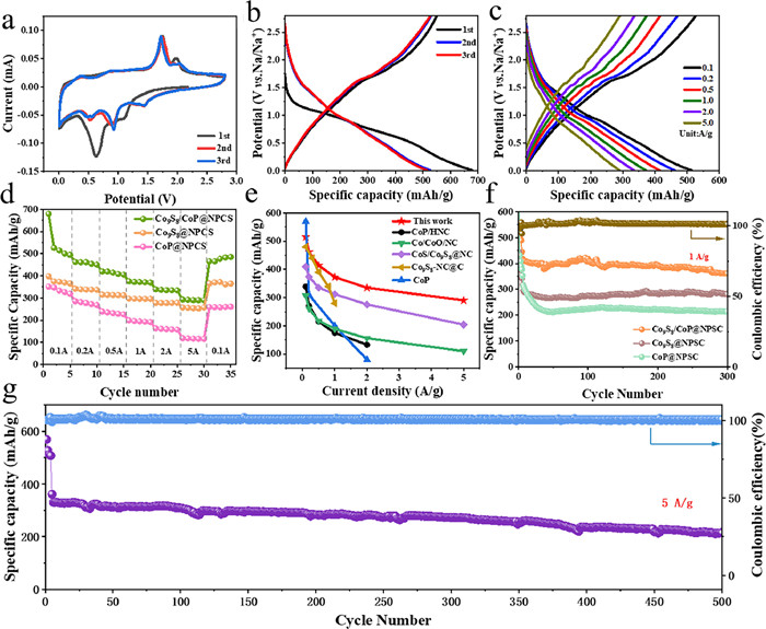
Fig. 3b illustrates the charging/discharging curves for the initial three cycles (0.1 A/g). We can observe that the voltage plateau of the CV curve and the charge/discharge curve are aligned with the initial capacity of 679.712/550.93 mAh/g, and the coulombic efficiency during the inaugural charging/discharging process is 81.1%. The charging/discharging curves of the last two cycles almost coincided, which indicates higher reversibility and a certain degree of stability of the Co9S8/CoP@NPSC structure. The GCD curves of Co9S8/CoP@NPSC at different current densities (Fig. 3c) have the same voltage platform at different potential currents and the trend of the curves is consistent, indicating good conductivity [26].
The rate performance plots of Co9S8/CoP@NPSC, Co9S8@NPSC, and CoP@NPSC are shown in Fig. 3d. The reversible specific capacities of Co9S8/CoP@NPSC were 495.41, 461.27, 414.48, 372.66, 335.27, and 290.28 mAh/g at current intensities ranging from 0.1 A/g to 5 A/g, respectively. The attenuation of the specific volume with the rise of the current intensity, when the current intensity was restored to 0.1 A/g, the specific capacity recovered to 485.46 mAh/g revealing excellent stability in cycling. In comparison, the reversible capacities of Co9S8@NPSC were 373.44, 339.29, 313.29, 296.43, 277.43, and 254.27 mAh/g, and those of CoP@NPSC were 332.89, 281.28, 231.64, 196.22, 159.51, and 116.36 mAh/g. Fig. 3e demonstrates the performance of Co9S8/CoP@NPSC material in comparison with previously reported anode electrode materials in SIBs, further highlighting its impressive electrochemical capabilities [27-31]. The cycling test demonstrated excellent reversible capacity and cycling consistency with a specific capacity of 360.47 mAh/g after 300 cycles at 1 A/g, which keeps 96.7% of the initial capacity (372.66 mAh/g) (Fig. 3f). Meanwhile, it can also maintain the high specific capacity of 213.96 mAh/g after 500 cycles at 5 A/g (Fig. 3g).
Cyclic voltammetry (CV) tests at different scan rates (0.1–1.0 mV/s) were performed to further investigate the sodium ion storage mechanism. The CV curves show a similar trend at various scan rates and six redox peaks can be seen (Fig. 4a), exhibiting an obvious pseudo-capacitive behavior. Typically, the current value (i) and scanning rate (v) of a reaction peak can be described by the equations [32]: I = av; logi = b × logv + loga; I(v) = k1 v + k2 v 1/2. Among them, the value of b points to the galvanic mechanism. Fig. 4b displays the b-values of each peak in the CV curves after linear fitting, the b-values of the three oxidation peaks are 0.92, 0.75, and 0.69, and the b-values of the three reduction peaks are 0.99, 0.86, and 0.90, which indicates that the capacitive behavior is dominant in the charge-discharge operation. Fig. 4c demonstrates the contributions of 79.12% (0.1 mV/s), 85.25% (0.2 mV/s), 86.46% (0.4 mV/s), 89.56% (0.6 mV/s), 90.99% (0.8 mV/s), and 92.61% (1.0 mV/s). We can observe that the capacitance contribution gradually increases and is as large as 92.61% at 1.0 mV/s (Fig. 4d). This revealed that the Co9S8/CoP@NPSC electrodes provide a significant number of reaction sites during the reaction process, which lays the foundation for stability and reversibility during the cycling process, thus contributing to the pseudocapacitance effect.
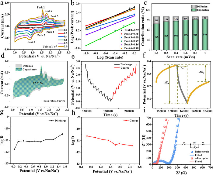
Constant current intermittent titration (GITT) is an electrochemical technique to test the diffusion coefficient of sodium ions during interfacial reactions. Fig. 4e illustrates the GITT test time-voltage plot of Co9S8/CoP@NPSC electrode material during a sole charge-discharge process. Fig. 4f shows a localized enlargement of the GITT test curve, ΔEs denotes the voltage difference and ΔE denotes the voltage fluctuation. The GITT is performed by applying a current pulse results in a rapid rise of the potential and makes it continue to rise at a constant current. Then when the applied current is disrupted, the potential falls rapidly, with the falling drop in voltage being proportional to the rapid rise in voltage that preceded it. When the applied current is interrupted, the potential will drop rapidly. The voltage drop will be proportional to the previous rapidly rising voltage and enter the relaxation stage. The relationship between voltage and time is obtained through the multiple "pulse-constant current-relaxation" process, the ion diffusion coefficient can be expressed by this equation:
In addition, the electrochemical performance of Co9S8/CoP@NPSC on potassium ion batteries was investigated in Fig. S7 (Supporting information). Fig. S7a shows the CV curves at 0.1 mV/s of Co9S8/CoP@NPSC for PIBs. The two tiny oxidation peaks at 1.24 V and 2.09 V during charging can be interpreted as related to the insertion of K+. The reduction peaks at 0.63 V and 0.95 V during discharging can be attributed to the extraction of K+. The CV curves reunited in the second and third cycles, which indicated that the Co9S8/CoP@NPSC anode material was highly reversible in storing K ions. A series of CV tests were carried out using cyclic voltammetry (0.1–1.0 mV/s) to further investigate the mechanism behind the potassium storage properties. Figs. S8a and b (Supporting information) show the b-values of the individual peaks in the linearly fitted CV curves with b-values ranging from 0.5 to 1, which suggests that capacitive behavior dominates the charging and discharging process. Figs. S8c and d (Supporting information) demonstrate the curves of the contribution rates, which are 33.63% (0.1 mV/s), 42.24% (0.2 mV/s), 49.29% (0.4 mV/s), 53.75% (0.6 mV/s), 58.36% (0.8 mV/s) and 62.07% (1.0 mV/s). This suggests that the Co9S8/CoP@NPSC electrodes provide active sites in the reaction, resulting in a rapid potassiation/depotassiation process, which lays the foundation for the stability and reversibility in the cycling process and contributes to the contribution of pseudocapacitance.
In Fig. S7b, we can observe that the voltage plateaus of the CV curves and the charge/discharge curves are consistent and the charge/discharge curves of the latter two cycles almost overlap, indicating the cycling stability of the Co9S8/CoP@NPSC electrode material in PIBs. The GCD curves of Co9S8/CoP@NPSC at various current densities were homogeneous (Fig. S7c). As shown in Fig. S7d, the specific capacities are 353.97 (0.1 A/g), 279.61 (0.2 A/g), 214.90 (0.5 A/g), 176.74 (1 A/g), 135.03 (2 A/g) and 90.31 mAh/g (5 A/g), when the current density was restored to the initial (0.1 A/g). The specific capacity was restored to 295.13 mAh/g, showing good cycle reversibility. Fig. S7e demonstrates the performance of Co9S8/CoP@NPSC material in comparison with previously reported anode materials in potassium ion batteries, further suggesting the excellent electrochemical performance [32-35]. From the EIS (Fig. S7f), it can be seen that the semicircle diameter after cycling is smaller than the semicircle diameter before cycling, which indicates that the cycle makes the resistance less and the conductivity increases. In the PIBs test, the specific capacity remained at 103.22 mAh/g (1 A/g) after more than 1000 cycles, demonstrating the outstanding cycling stability (Fig. S7g).
An in-depth understanding of the electrochemical sodium ion storage mechanism was studied by ex-situ XRD, XPS, SEM and EIS characterization analyses. The sodium ion storage mechanism of Co9S8/CoP@NPSC in an initial cycle was revealed by ex-situ XRD analysis from 0.1 V to 2.8 V at 0.2 A/g (Fig. 5a). The ex-situ XRD covered the entire discharge process at 1.45, 0.93, 0.6, 0.01 V and the charging process at 1.72, 2.0, 2.8 V, respectively. The diffraction peaks at 43.26° and 50.41° belong to the diffraction peaks of Cu. When the cell was being discharged to 1.45 V, the spreading of the peaks at 25.23°, 29.58°, 38.98°, 41.97°, and 44.66° corresponded to CoP, Co9S8, Na2S, Na3P, and Co, which revealed the conversion reactions of Co9S8 to Co and Na2S and CoP to Co and Na3P. The diffraction peaks of CoP and Co9S8 disappeared when the cell was drained to 0.93 V. As the cell was charged to 1.72 V, one new amplification peak appeared at 26.56°, which corresponded to Co9S8 revealed a reversible conversion of Co and Na2S to Co9S8; upon charging the battery to 2.8 V, a new derivatization peak at 52.43° appeared corresponding to CoP, which revealed a reversible conversion reaction of Co and Na3P to CoP. The peaks of Na2S and Na3P appeared throughout the charging and discharging process, which suggests a multistep chemical reaction process including insertion and extraction reactions [36, 37].
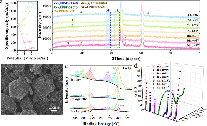
Ex-situ SEM tests were performed for the circulation of the electrodes as shown in Fig. 5b and Fig. S9 (Supoprting information), it can be observed that there is little change in the morphology of Co9S8/CoP@NPSC after cycling, which suggests that the stability is good and the stabilized structure is conducive for the material to show excellent performance in the long cycling test. In the Co 2p spectrum (Fig. 5c), the Co2+ (801.68 eV, 786.08 eV) and Co3+ (796.78 eV, 780.28 eV) peaks showed an increasing/decreasing trend in the charging/discharging state. When fully discharged down to 0.01 V, a fresh peak at 779.48 eV appeared, which may well point to the conversion product Co0. While at 2.8 V, these characteristic peaks disappeared, which is attributed to the continuous occurrence of transformation and alloying reactions [38, 39]. In addition, we performed ex-situ EIS tests (Fig. 5d). During the discharge process, the resistance exhibited an increasing trend, which can be attributed to the formation of Na2S and Na3P. During charging, the resistance tends to gradually decrease, a phenomenon that can be attributed to the decomposition and transformation of Na2S and Na3P [40]. From the above ex-situ analysis, the multi-step reaction of the Co9S8/CoP@NPSC heterostructure can be inferred as follows:
|
|
(1) |
|
|
(2) |
|
|
(3) |
|
|
(4) |
In summary, yolk-shell cobalt phosphorus sulfide nanocrystals were encapsulated into a polyheterogeneous atom-doped carbon framework to form a dodecahedral yolk-shell structured anode material (Co9S8/CoP@NPSC) by a polymer-coating process and a high-temperature calcination process of phosphorus sulfide. The doping of N, P, S and the synergistic effect of Co9S8 and CoP can induce more energy storage active sites and enhance the reversible capacity of the electrode. The dodecahedral yolk-shell structure effectively prevents the aggregation of the inner shell material and ensures long-term stability. In addition, the ex-situ XRD, SEM, XPS, and EIS characterization comprehensively demonstrated the whole chemical reaction process and better showed the energy storage mechanism. The Co9S8/CoP@NPSC is expected to be used as the anode material for SIBs and PIBs.
Yining Li: Writing – review & editing, Writing – original draft. Shimei Wu: Investigation. Lantao Chen: Investigation. Haosen Fan: Validation, Supervision. Yufei Zhang: Validation, Supervision. Lingxing Zeng: Validation, Supervision.
This work was supported by National Natural Science Foundation of China (Nos. 52472194, 52101243), Natural Science Foundation of Guangdong Province, China (No. 2023A1515012619) and the Science and Technology Planning Project of Guangzhou (No. 202201010565).
Supplementary material associated with this article can be found, in the online version, at doi:
P. Xia, S. L. Li, L. Yuan, et al., J. Membr. Sci. 694 (2024) 122395. doi: 10.1016/j.memsci.2023.122395
X.Y. Jin, X.C. Guo, S.Y. Dong, et al., Chin. Chem. Lett. 36 (2025) 110604. doi: 10.1016/j.cclet.2024.110604
P. F. Wan, X. L. Peng, S. Y. Dong, et al., J. Colloid Interface Sci. 657 (2024) 757-766. doi: 10.1016/j.jcis.2023.12.013
F. Xu, S. L. Li, S. D. Jing, et al., J. Colloid Interface Sci. 660 (2024) 907-915. doi: 10.1016/j.jcis.2024.01.138
M. He, R. Davis, D. Chartouni, et al., J. Power Sources 548 (2022) 232036-232044. doi: 10.1016/j.jpowsour.2022.232036
R. Sun, P. Xia, X. C. Guo, et al., Chem. Eng. J. 486 (2024) 150377. doi: 10.1016/j.cej.2024.150377
R. Sun, F. Xu, C.H. Wang, et al., Rare Met. 43 (2024) 1906-1931. doi: 10.1007/s12598-023-02563-y
Q. R. Hu, S.L. Wang, Y. Zhang, et al., J. Alloys Compd. 491 (2010) 707-711. doi: 10.1016/j.jallcom.2009.11.050
L. Chen, Z. Liu, W. Yang, et al., J. Colloid Interface Sci. 666 (2024) 416-423. doi: 10.1016/j.jcis.2024.04.044
Y. Ma, M. Wu, L. Li, et al., Appl. Surf. Sci. 600 (2022) 154159-154169. doi: 10.1016/j.apsusc.2022.154159
A. Hua, W. Zhou, Y. Li, et al., J. Alloy. Compd. 895 (2022)162668-162677. doi: 10.1016/j.jallcom.2021.162668
S. J. Lu, J. Y. Lin, C. H. Wang, et al., Rare Met. 43 (2024) 3713-3723. doi: 10.1007/s12598-024-02650-8
Y. Jiang, J. Liang, L. Yue, et al., J. Colloid Interface Sci. 604 (2021) 319-326. doi: 10.1016/j.jcis.2021.06.145
T. Meng, J. Qin, D. Xu, et al., ACS Appl. Mater. Interfaces 11 (2019) 9023-9032. doi: 10.1021/acsami.8b19341
Y. Han, W. Jiang, J. Jiang, et al., J. Electron. Mater. 51 (2022) 2909-2917. doi: 10.1007/s11664-022-09556-0
H. Zhu, S. Dong, J. Xiong, et al., J. Colloid Interface Sci. 641 (2023) 942-949. doi: 10.1016/j.jcis.2023.03.083
Y. Hu, W. Li, Z. Wei, et al., Int. J. Electrochem. Sci. 18 (2023) 100180-100188. doi: 10.1016/j.ijoes.2023.100180
X. Tao, Y. Li, H.G. Wang, et al., J. Colloid Interface Sci. 565 (2020) 494-502. doi: 10.1016/j.jcis.2020.01.018
Y. Peng, Y. Bai, C. Liu, et al., Coordin. Chem. Rev. 466 (2022) 214602-214622. doi: 10.1016/j.ccr.2022.214602
S. Wu, F. Xu, Y. Li, et al., J. Colloid Interface Sci. 660 (2024) 97-105. doi: 10.1117/12.3035867
Y. Li, J. Zhang, Q. Chen, et al., Adv. Mater. 33 (2021) 2100855. doi: 10.1002/adma.202100855
J. Wei, C. Jiang, B. Chen, et al., Ceram. Int. 47 (2021) 25387-25397. doi: 10.1016/j.ceramint.2021.05.261
X. Li, L. Jiang, J. Liu, et al., J. Energy Chem. 43 (2020) 121-128. doi: 10.1134/s0001434620010113
P. Long, Z. Zhang, G. Peng, et al., New J. Chem. 41 (2017) 9184-9191. doi: 10.1039/C7NJ01871A
X. Wang, Z. Na, D. Yin, et al., ACS Nano 12 (2018) 12238-12246. doi: 10.1021/acsnano.8b06039
B. Qin, M. Wang, Z. Liu, et al., J. Colloid Interface Sci. 646 (2023) 597-605. doi: 10.1016/j.jcis.2023.05.077
W.J. Li, Q.R. Yang, S.L. Chou, et al., J. Power Sources 294 (2015) 627-632. doi: 10.1016/j.jpowsour.2015.06.097
Y.V. Kaneti, J. Zhang, Y.B. He, et al., J. Mater. Chem. A 5 (2017) 15356-15366. doi: 10.1039/C7TA03939E
Y. Qi, T. Zhang, N. Wu, et al., ACS Appl. Energy Mater. 4 (2021) 5574-5582. doi: 10.1021/acsaem.1c00271
L. Fu, C. Kang, W. Xiong, et al., J. Colloid Interface Sci. 595 (2021) 59-68. doi: 10.1016/j.jcis.2021.03.127
Y. Lian, F. Chen, H. Kang, et al., Appl. Surf. Sci. 507 (2020) 145061-145069. doi: 10.1016/j.apsusc.2019.145061
J. Ye, F. Ge, G. Xia, et al., Mater. Lett. 282 (2021) 128687-128691. doi: 10.1016/j.matlet.2020.1286877.01.026
W. Miao, X. Zhao, R. Wang, et al., J. Colloid Interface Sci. 556 (2019) 432-440. doi: 10.1016/j.jcis.2019.08.090
S. Zhang, F. Ling, L. Wang, et al., Adv. Mater. 34 (2022) 2201420. doi: 10.1002/adma.202201420
M. Wang, B. Qin, S. Wu, et al., J. Colloid Interface Sci. 650 (2023) 1457-1465. doi: 10.1016/j.jcis.2023.07.071
X. Liu, F. Xu, Z. Li, et al., Coord. Chem. Rev. 464 (2022) 214544. doi: 10.1016/j.ccr.2022.214544
M. Wang, B. Qin, F. Xu, et al., J. Colloid Interface Sci. 650 (2023) 446-455. doi: 10.1016/j.jcis.2023.07.007
S.M. Wu, Y.N. Li, L.T. Chen, et al., Chin. Chem. Lett. 36 (2025) 109796. doi: 10.1016/j.cclet.2024.109796
T. Li, Y. Xia, H. Wu, et al., Nanoscale 14 (2022) 10226-10235. doi: 10.1039/d2nr02232j
Y. Xu, J. Sun, Y. He, et al., Sci. China Chem. 64 (2021) 1401-1409. doi: 10.1007/s11426-021-1057-3

Figure 1 (a, b) SEM images, (c, d) TEM images, (e, f) HRTEM images, (g) element mapping images of Co9S8/CoP@NPSC.

Figure 2 XPS spectrum of Co9S8/CoP@NPSC: (a) Full-scan spectrum; (b) C 1s; (c) Co 2p; (d) S 2p; (e) N 1s; (f) P 2p region.

Figure 3 (a) CV of first three revolutions at 0.1 mV/s. (b) Discharge-charge profiles of the first three cycles at 100 mA/g. (c) Galvanostatic profiles at different current densities. (d) Rate performance of Co9S8/CoP@NPSC, Co9S8@NPSC and CoP@NPSC. (e) Comparison of rate capability of Co9S8/CoP@NPSC with previously studied electrode materials for SIBs. (f) Cycle performance of Co9S8/CoP@NPSC, Co9S8@NPSC and CoP@NPSC at 1.0 A/g in SIBs. (g) Cycle performance of Co9S8/NC at 5.0 A/g in SIBs.

Figure 4 (a) CV profiles at various scan rates. (b) The corresponding logi vs. logv plots. (c) The contribution of capacitive behavior at 1.0 mV/s. (d) Capacitive contribution at various scan rates. (e) Discharge-charge profiles for GITT. (f) Enlarged potential response overtime during a single current pulse. Diffusion coefficient of Na+ in (g) discharging and (h) charging process. (i) Nyquist curves of Co9S8/CoP@NPSC at SIBs.

Figure 5 (a) Ex-situ XRD of Co9S8/CoP@NPSC anode in different voltage during cycling processes. (b) SEM image of Co9S8/CoP@NPSC electrode after cycling. (c) Ex-situ XPS of Co 2p at different potential platforms during the discharging/charging process. (d) Ex-situ Nyquist plots at predetermined potentials of the Co9S8/CoP@NPSC electrode.

 扫一扫看文章

扫一扫关注我们
 DownLoad:
 下载:
下载:
 下载:
下载: