Citation:
Hongfei Li, Hao Chen, Qi Kang, Lihe Guo, Xingyi Huang, Haiping Xu. Gel polymer electrolyte for flexible and stretchable lithium metal battery: Advances and prospects[J]. Chinese Chemical Letters,
2025, 36(9): 110325.
doi:
10.1016/j.cclet.2024.110325
Gel polymer electrolyte for flexible and stretchable lithium metal battery: Advances and prospects
English
Gel polymer electrolyte for flexible and stretchable lithium metal battery: Advances and prospects
School of Energy and Materials, Shanghai Key Laboratory of Engineering Materials Application and Evaluation, Shanghai Polytechnic University, Shanghai 201209, China
b.
Department of Polymer Science and Engineering, Shanghai Key Laboratory of Electrical Insulation and Thermal Aging, School of Chemistry and Chemical Engineering, Shanghai Jiao Tong University, Shanghai 200240, China
Received Date:
15 June 2024 Accepted Date:
08 August 2024 Revised Date:
10 July 2024 Available Online:
15 September 2025
Abstract:
Flexible and stretchable energy storage devices are highly desirable for wearable electronics, particularly in the emerging fields of smart clothes, medical instruments, and stretchable skin. Lithium metal batteries (LMBs) with high power density and long cycle life are one of the ideal power sources for flexible and stretchable energy storage devices. However, the current LMBs are usually too rigid and bulky to meet the requirements of these devices. The electrolyte is the critical component that determines the energy density and security of flexible and stretchable LMBs. Among various electrolytes, gel polymer electrolytes (GPEs) perform excellent flexibility, safety, and high ionic conductivity compared with traditional liquid electrolytes and solid electrolytes, fulfilling the next generation deformable LMBs. This essay mainly reviews and highlights the recent progress in GPEs for flexible/stretchable LMBs and provides some useful insights for people interested in this field. Additionally, the multifunctional GPEs with self-healing, flame retardant, and temperature tolerance abilities are summarized. Finally, the perspectives and opportunities for flexible and stretchable GPEs are discussed.
The rapid development of advanced flexible and stretchable energy storage devices is driven by the worldwide used of wearable clothes, electronic skins, implantable medical devices, flexible sensing devices, and smart portable electronics [1-9]. The power system for flexible and stretchable energy storage devices should be lightweight, thin, flexible, and sustainable [10-20]. Despite commercialized power sources such as supercapacitors and lithium-ion batteries (LIBs) have been widely investigated for flexible and stretchable devices over the past two decades, the low energy density of these power devices has been unable to meet the increasing demands [21-24]. Lithium metal batteries (LMBs) have been put forward as a potential candidate for flexible and stretchable electronics due to the high theoretical gravimetric specific capacities (3862 mAh/g) and volumetric specific capacities (2062 mAh/cm3), as well as low redox potential (−3.04 vs. standard hydrogen electrode) [25-31]. Unfortunately, there are several intractable issues of flexible LMBs that should be overcome before their successfully commercialized.
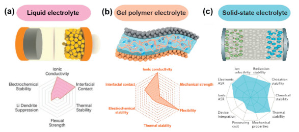
LMBs are mainly composed of five fundamental components: cathode, anode, electrolyte separator, current collector, and packaging materials [32, 33]. Each component plays a critical role in the operation of battery. Among of them, electrolyte separator is a key component of LMBs, which separate the cathode and the anode while transporting ions simultaneously [34-38]. Electrolyte separator with excellent deformability is highly essential for flexible and stretchable LMBs. Electrolyte separators can be divided into three categories including liquid electrolytes, gel polymer electrolytes (GPEs), and solid-state electrolytes (SSEs) [39-42], as demonstrated in Fig. 1. Liquid electrolytes have good interfacial impedance between the electrodes and electrolytes, along with excellent ionic conductivity. However, their liquid nature may give rise to leakage and short-circuit under deformation, posing serious safety risk. SSEs are inherently solvent-free and solid, enabling them to handle leakage, polysulfide shuttle, and Li dendrite growth. Nevertheless, the high interfacial resistance between the electrodes and SSEs, as well as the low ionic conductivity, will deteriorate the long-term cycling performance of LMBs. GPEs, which combine the advantages of both liquid electrolytes and SSEs, have attracted considerable attention in recent years.
Figure 1
Figure 1.
Schematic illustration and performance comparisons of (a) the liquid electrolyte, (b) gel polymer electrolyte, and (c) solid-state electrolyte. Reproduced with permission [40-42]. [40] Copyright 2020, Wiley-VCH. [41] Copyright 2022, American Chemical Society. [42] Copyright 2017, Springer Nature.
GPEs, also known as quasi-solid-state electrolytes, are composed of liquid electrolytes and cross-linked polymer matrices [43-46]. GPEs exhibit high lithium-ion transference number, good interfacial compatibility with electrodes, polysulfide-blocking properties, excellent chemical stability, and mechanical strength, making them as promising materials for the practical flexible and stretchable energy storage devices. To date, polymers include poly(ethylene oxide) (PEO), poly(vinyl alcohol) (PVA), poly(propylene oxide) (PPO), poly(vinylpyrrolidone) (PVP), poly(acrylonitrile) (PAN), biocompatible cellulose, poly(methyl methacrylate) (PMMA), poly(ethylene glycol) (PEG), and poly(vinylidene fluoride) (PVDF) are explored as the polymer matrix for GPEs [47-57]. Water, organic solvents, and ion liquids are carried out as the medium for dissociating lithium salts [58]. Tremendous efforts have been devoted to produce GPEs with high performances. People have successfully developed several approaches to prepare GPEs by casting method, phase-inversion method, sol-gel processing, electrospinning, and in-situ polymerization [59-65]. Besides, numerous approaches have been developed to optimize the performance of GPEs. For example, excellent resilience is an important property for GPEs, physical or chemical cross-linked structure can be introduced into GPEs towards outstanding mechanical deformations [66-68]. Inorganic nanoparticles (such as TiO2, Al2O3, BN, and SiO2) or organic molecules as reinforcing agents are generally introduced into the polymer matrix to ensure sufficient mechanical robustness [69-71].
Although a large number of articles have been published referring to GPEs, there is a lack of in-depth exploration regarding their application in flexible and stretchable LMBs. In this paper, the latest achievements in the design, fabrication strategies, and performances of GPEs for flexible and stretchable LMBs are summarized. As a crucial component of LMBs, GPEs must exhibit favorable electrochemical and physical characteristics to mitigate prominent issues, including concerns related to lithium dendrites growth, the electrode-electrolyte interface, polysulfide diffusion, and the undesired side reaction of Li anode. Additionally, various configurations of flexible and stretchable LMBs are outlined. Last but not the least, GPEs with multi-functionality, including self-healing properties, non-flammability, and temperature tolerance, are briefly examined. In conclusion, this paper summarizes the developmental prospects of GPEs in flexible and stretchable LMBs and provides an outlook on their future research directions.
2.
GPEs based on physical/chemical preparation methods
Typically, GPEs consist of liquid electrolytes, additives, and polymer matrices. Different from traditional porous polyolefin separators, liquid electrolytes of GPEs are imprisoned in polymer networks and have strong interaction with polymer skeleton, eliminating the fluidity of liquid nature but maintaining high ionic conductivity. As a result, GPEs amalgamate the benefits of liquid electrolytes and solid polymer electrolytes, rendering them one of the most promising electrolyte materials for flexible and stretchable LMBs. Up to now, various strategies have been developed to prepare high-performance GPEs, such as casting method, phase-inversion method, sol-gel processing, electrospinning, in-situ polymerization, and 3D-printed manufacturing. The electrochemical performances of GPEs prepared by different methods for LMBs are listed in Table 1. Nevertheless, several obstacles still require resolution. For instance, (1) the abundant of liquid plasticizers in GPEs greatly reduced their mechanical properties, causing poor cycling stability under continuously deformation; (2) polysulfide dissolve in electrolyte and transport to anode deteriorate the capacity of LMBs; (3) unstable solid electrolyte interphase (SEI) is easy to be destroyed under deformation; (4) poor chemical and mechanical thermal stability under high temperature. In this section, the current preparation of GPEs for flexible and stretchable LMBs are reviewed and discussed as below, and these advanced projects provide useful approaches to solve the above problems.
Table 1
Table 1.
Summary and comparison of representative examples of GPEs prepared by different methods for LMBs.
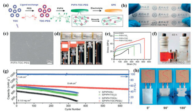
The casting method provides a straightforward approach for preparing GPEs by casting a mixture solution of polymer and nanoparticle onto a suitable plate. After solvent evaporation, the resulting film will absorb liquid electrolyte to form the GPE. Zheng and coworkers prepared a PEG covered titanium-oxo nano-clusters (TOC-PEG) reinforced poly(vinylidene fluoride-co-hexafluoropropylene)-based (PVFH) GPE for the construction of low E/S Li-S batteries (Fig. 2) [72]. Initially, they fabricated a thin PVFH-TOC-PEG membrane through casting, which was subsequently immersed in the electrolyte to produce the GPE (Figs. 2a and b). SEM image (Fig. 2c) revealed that the PVFH-TOC-PEG surface exhibited highly dense, smooth, and pinhole-free. The PVFH-TOC-PEG membrane demonstrated remarkable mechanical strength (50 MPa) even after immersion in the electrolyte, which was twice than that of pure PVFH (Figs. 2d and e). Furthermore, the PVFH-TOC-PEG GPE exhibited greater compactness, leading to excellent prevention of polysulfide migration (Fig. 2f). The constructed Li-S battery, featuring high sulfur loading (10 mgS/cm2) and a low negative/positive capacity ratio (1/1), achieved a gravimetric energy density of 423 Wh/kg and sustained operation for 100 cycles (Fig. 2g). A soft-packed S|PVFH-TOC-PEG|Li battery was assembled to explore its potential application in flexible batteries. The assembled battery successfully powered lamps even under various deformations, indicating the promising potential of this GPE for flexible batteries (Fig. 2h). It is noteworthy that this work presents a new opportunity for the scalable production of GPE with high electrolyte loading and robust mechanical strength through casting.
Figure 2
Figure 2.
Synthesis and properties of PVFH-TOC-PEG GPE. (a) Schematic illustration for the synthesis of the PVFH-TOC-PEG electrolyte. (b) Photograph image of the PVFH-TOC-PEG membrane. (c) SEM image of PVFH-TOC-PEG membranes. (d) The PVFH-TOC-PEG electrolyte pressed with a metal bar and stress-strain measurement of the PVFH-TOC-PEG membrane. (e) Polysulfide permeation tests for the GPE. (f) Stress-strain curves of the PVFH-based membranes. (g) Cycling performance of the GPE Li-S cells at 8 mA/cm2. (h) Flexible S|PVFH-TOC-PEG|Li battery evaluated under different conditions. Reproduced with permission [72]. Copyright 2020, Royal Society of Chemistry.
The introduction of inorganic nanofillers into GPEs providing an effective strategy to further improve the properties. Hexagonal boron nitride (BN), known as white graphene, exhibits intriguing properties such as high mechanical strength, electrical insulation, chemical stability, and thermal conductivity, all of which are advantageous for electrolyte applications [73-77]. Lee and his coworkers prepared a PVH (PVDF-HFP)-based GPE with BN (G-CFBN) as an additive to enable a safe, long lifespan, and high rate LMB by casting method [78]. They found that a minimal addition (0.5 wt%) of BN into the PVH can great decreased the crystallinity of the PVH and generated a more porous structure, leading to enhanced ionic conductivity through increased electrolyte loading. The fabricated Li|G-CFBN|LFP battery achieved a long lifespan more than 500 cycles even at 10 C rate. The superior performance made this novel composite GPE for flexible LMB applications.
2.2
Preparation GPEs by phase-inversion method
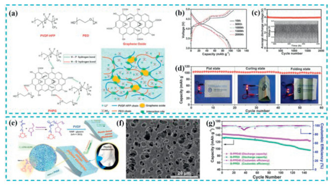
Phase-inversion method is a simple and cost-effective approach for preparing GPEs. It can be described as the initially polymer solution is transformed into a solid state by controlled methods, such as wet phase-inversion method and dry phase-inversion method [79-83]. The mainly principle of wet phase-inversion method is exchanging the original solvent of gel with a non-solvent, resulting in a significant porous structured membrane that facilitates the uptake of a large amount of liquid electrolyte. While, the dry phase-inversion method, also known as thermally induced phase separation, is dissolving a polymer in a high-boiling-point solvent at high temperature, after that, the solution in a desired holder is cooled to induce phase separation and solidification to generate a microporous membrane. PEO has been extensively investigated as a host material for preparing SSEs due to the ability of the CH2CH2O unit in PEO to coordinate with Li+ and provide pathways for lithium-ion transport [84]. However, its poor ionic conductivity and low melting point restricts its further application in Li batteries. Poly(ethylene glycol) diglycidyl ether (PEGDE) was reacted with branched-polyethylenimine (PEI) to prepare a host materials, which was then used to prepare GPE by dry phase-inversion method [85]. The abundance of polar groups in the GPE generated strong interactions with polysulfides, suppressed the polysulfide shuttling. The fabricated quasi-solid-state Li-S battery achieved a high specific capacity of 950 mAh/g at 0.2 C and superior capacity retention of 98% after 100 cycles at 0.5 C, outperforming the corresponding PEO battery. PVDF is another ideal polymer matrix for Li+ transport due to its relatively high dielectric constant and low crystallinity [86, 87]. Tang et al. reported the preparation of a PVDF-HFP-based GPE using the dry phase-inversion method [88]. They combined PVDF-HFP with PEO and graphene oxide (GO) to create a 3D cross-linked porous network through weak hydrogen bond interactions (Fig. 3a). A GPE named PHPG, exhibiting high ionic conductivity (2.1 × 10⁻³ S/cm), was obtained after filling the porous structure with liquid electrolyte. Electrochemical impedance spectroscopy was conducted to assess the cycling stability of the PHPG-based battery, revealing minimal polarization in the charge/discharge curves at 5 C, indicating excellent stability of the PHPG-based battery (Fig. 3b). The discharge voltage of the battery was maintained at 4.0 V with a retention of 97.6% after 2000 cycles (Fig. 3c). Furthermore, the fabricated flexible LMB cell demonstrated outstanding cycling performance, retaining 92% of its capacity after 2000 cycles at a high current rate of 5 C. Subsequently, a flexible battery was tested under curling and folding conditions (Fig. 3d), and it successfully powered two lamps for more than 50 cycles, demonstrating excellent stability. Martin Kaltenbrunner et al. utilized a polymerized high internal phase emulsions (polyHIPEs) method to prepare a GPE separator with highly ionic conductivity for stretchable metal batteries [89]. The separators prepared by polyHIPEs exhibited high porosity (> 80%) and high ionic conductivity, while retaining excellent stretchability up to 50% strain. A stretchable battery utilizing this GPE powered an untethered audio controller, demonstrating its potential application in stretchable electronics. Cao and colleagues prepared a GPE based on hydroxypropyl methyl cellulose (HPMC) and polyacrylonitrile (PAN) by a simple wet phase-inversion method [90]. The physically cross-linked gel electrolyte performed excellent mechanical stability upon deformation, serving as a stretchable separator. The prepared stretchable battery exhibited a high areal capacity of 106 mAh/g at 2 C, superior electrochemical performance with a Coulombic efficiency up to 98.9%, and long-term stability of 94.2% after 100 cycles. Recently, it was reported that the lithium-ion transference number of GPEs could be increased via enhanced the interactions between anions the polymer main chains. A cyclic boroxine-based copolymer (40 wt%) was mixed with PVDF (60 wt%) to prepare a dense, uniform, and well-interconnected porous structured electrolyte membrane by the phase-inversion method (Figs. 3e and f) [91]. It was found that the existence of acid-base interaction between boron moieties of polymer chains and the anions of the lithium salt, significant improving the lithium-ion transference number. The prepared GPE exhibited a high ionic conductivity of 1.32 × 10⁻³ S/cm at ambient temperature. Moreover, they fabricated an LMB based on this GPE, which exhibited a specific discharge capacity of 123 mAh/g with 86% retention after 150 cycles (Fig. 3g).
Figure 3
Figure 3.
(a) Schematic of the intermolecular hydrogen binding effect between PVDF-HFP, PEO, and GO in the PHPG polymer, and schematic of the 3D porous polymer network of PHPG formed by the intermolecular hydrogen binding effect. (b) Charge/discharge curves of the PHPG-DIB at the 10th, 500th, 1000th, 1500th, and 2000th cycle at 5 C. (c) Average discharge voltage of the PHPG-DIB at 5 C over 2000 cycles. (d) Cycling performance of the flexible PHPG-DIB under flat, curling, and folding state at 2 C. Reproduced with permission [88]. Copyright 2018, Wiley-VCH. (e) Process of the borate-based porous polymer electrolyte. (f) SEM image of the borate-based porous polymer electrolyte membrane. (g) Cycling performance of fabricated LFP/Li cells using the borate-based porous polymer electrolyte at 0.2 C. Reproduced with permission [91]. Copyright 2021, American Chemical Society.
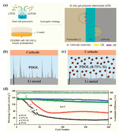
In-situ polymerization provides a novel method for preparing high performance GPEs for LMBs [92-98]. It could simplify the assembly process and dissolution the interface issue between electrolyte and electrodes. For instance, Liu et al. described a facile in-situ synthesis of pentaerythritol tetraacrylate based GPE on the surface of the sulfur cathode [99]. This novel GPE presented high ionic conductivity (1.13 × 10⁻² S/cm) attributable to its porous structure at room temperature. Additionally, the GPE promoted the formation of a flexible and stable passivation layer on the sulfur electrode. As a result, the fabricated LMB performed high specific capacity (601.2 mAh/g at 1 C) and improved capacity retention (81.9% after 400 cycles at 0.5 C). Furthermore, the soft packed S/GPE/Li battery could power a red light-emitting diode lamp even under large shape deformation such as flatted, bent, or even clustered states. Another in-situ polymerization approach is to inject monomers and electrolytes into porous separators, which can successfully wet both the cathode and anode. Subsequently, a thermal condition or current is applied to initiate polymerization. Both the interfacial compatibility and dendrite growth issues are effectively alleviated by this method. Li et al. innovatively achieved regulated interfacial compatibility between electrodes and separator through an in-situ gelation process (Fig. 4a) [100]. 1, 3-Dioxolane (DOL) on Li metal was ring-opening polymerization using organic lithium difluoro(oxalato)borate (LiDFOB) as initiator, to ensure adequate contact between the electrodes and GPE. Succinonitrile (SN) as a plasticizer was introduced into the system to enhance the ionic conductivity. It was found that a cathode electrolyte interphase about 7 nm was formed on the cathode surface, which was beneficial for the inhibition of dendrite growth and the improvement of the anode electrochemical stability. An LMB of LiFePO4|poly-DOL GPE| Li plate presented an extremely long lifespan of 1000 cycles with a capacity retention of 83.55%. Guo et al. reported the preparation of GPE for LMB by in-situ polymerization [101]. They impregnated cellulose nonwoven with a mixed solution of poly(ethylene glycol) diacrylate, ethoxylated trimethylolpropane triacrylate, electrolyte, LiTFSI, LiPF6, and AIBN, which was subsequently used to assemble LMB. The GPE-type cell can be facile obtained after curing the cell at 60 ℃. This kind of cell presented a high ionic conductivity of 0.56 mS/cm with a robust SEI on the lithium metal surface at room temperature. The cell's achieved 87.93% capacity retention after cycling for 300 cycles, demonstrating that the GPE could improve the cycling performance of LMBs. However, most GPEs are soft and cannot entire inhibit the growth of lithium dendrites. Incorporating additives into GPEs is an effective way to suppress the growth of lithium dendrites. Si nanoparticles were selected to be added into a DOL precursor solution, which was used to prepare GPE via in-situ polymerization method [102]. Si nanoparticles were immobilized in the GPE and effectively suppressed the growth of lithium dendrites (Figs. 4b and c). It was found that the presence of an appropriate amount of Si nanoparticles contributed to the generation of stable LiF-rich SEI films. As a result, the LFP/PDOL-0.75% Si/(Si/C) full cell maintained a capacity of 142.6 mAh/g with a retention of 93.2% at 0.5 C after 200 cycles (Fig. 4d), indicating excellent cycling performance.
Figure 4
Figure 4.
Preparation of the poly-DOL GPE. (a) Schematic illustrations of a synergetic strategy of in-situ synthesis of a GPE and pretreatment on Li metal. Reproduced with permission [100]. Copyright 2020, American Chemical Society. (b, c) The schematic diagrams of Si nanoparticles inhibiting the growth of lithium dendrites. (d) Cycling performances at 1 C of untreated/pretreated-Li|GPE|LiFePO4 batteries. Reproduced with permission [102]. Copyright 2020, American Chemical Society.
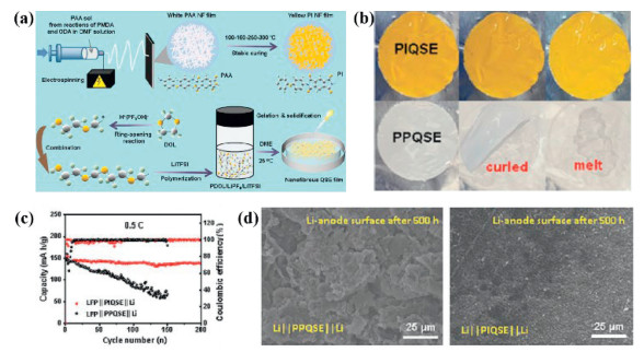
Ionic liquids (ILs) have drawn increasing attention in electrochemical devices in recent years [103-105]. Compared to liquid electrolytes, ILs are nonvolatile, thermal stability, nonflammable, and possess wider operating voltage [106, 107]. Therefore, they have a promise application in lithium batteries. Sol-gel processing is the most widely used method for the preparation of ionogels. The produced ionogels are highly homogeneous, and the procedure is carried out under mild condition. Guo and coworkers reported an ionogel electrolyte with an ant-nest architecture using sol-gel processing [108]. Ionic liquid N-propyl-N-methylpyrrolidinium bis(trifluoromethylsulfonyl)imide (Py13TFSI) was confined within a chemically modified SiO2 scaffold, the complex network structure providing multiple channels for ion transporting, while the formation of a particle-rich protective layer on the lithium plate suppressing the Li dendrite growth during the stripping/plating. As a result, the as-prepared full cell showed a high energy density of 390 Wh/kg, excellent cycling stability up to 3000 cycles, and a Coulombic efficiency exceeding 99.8%. Subsequently, the same group inspired by the Tai Chi philosophy of balancing rigid and flexible two phases, they synthesized a rigid-flexible hybrid ionogel electrolyte for Li battery by sol-gel processing. This GPE consisted of PVDF-HFP flexible framework, TiO2 rigid framework, and Py13TFSI ionic liquid [109]. The quasi-solid rigid-flexible ionogel electrolyte performed high Li+ conductivity (7.4 × 10⁻³ S/cm at 25 ℃) and high oxidation stability (5.5 V versus Li/Li+). The LiFePO4|ionogel electrolyte|Li cell extended cycling lifespan up to 800 h at a current density of 0.1 mA/cm2. Ding et al. developed a series of organogel ionic conductor (OIC) for soft robots, flexible electronics, and wearable devices [110, 111]. The synthesized OICs presented many unique advantages, including high transparency, stretchability, high ionic conductivity, and a wide voltage window (5.0 V). Yan et al. fabricated porous PI NF films by using a sol-gel electrospinning technique, which were then filling with DOL, 1, 2-dimethoxyethane (DME), lithium trifluoromethane sulfonimide (LiTFSI), and LiPF6 to prepare a PI-based GPE (Fig. 5a) [112]. The quasi-solid electrolytes exhibited high ionic conductivity and thermal stability, and was able to endure high temperature even at 120 ℃ and 160 ℃ for 2 h with no dimensional changes (Fig. 5b). Moreover, the electrochemical performances of the PI-based GPE were further investigated by testing LiFePO4|PIQSE|Li cells. The LiFePO4|PIQSE|Li cells showed a discharge capacity of 151.8 mAh/g with a high retention capacity of 91.8% over 200 cycles, indicating good cycling stability (Fig. 5c). The morphology of the cycled Li-metal anodes was characterized by SEM testing, as shown in Fig. 5d. It was found that Li|PIQSE|Li cells exhibited more uniform lithium deposition and smaller lithium grain size, which were beneficial to the high stable and safe cells. These works demonstrate the potential applications of the GPE utilized in flexible and stretchable electronics.
Figure 5
Figure 5.
(a) Controllable fabrication of PI NF films with a sol-gel electrospinning followed by a step heating. (b) Thermal shrinkage behaviors of the PIQSE and PPQSE films at 50 ℃ for 2 h, 120 ℃ for 2 h, and 160 ℃ for 2 h. (c) Long-cycling behavior of the quasi-SSLBs with LiFePO4 cathodes at 0.5 C. (d) Surface morphological changes of Li-anodes after 500 h in the symmetric cells with PPQSE and PIQSE. Reproduced with permission [112]. Copyright 2022, Wiley-VCH.
2.5
Preparation GPEs by electrospinning processing
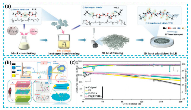
Electrospinning technique has attracted increasing attention in the past several decades due to its capability to fabricate nanofibers with abundant porosity, controllable nanofiber diameter, arrangement, and functionality [113-117]. Yang et al. prepared a sandwich structured GPE by electrospinning processing, which was consisted of PVDF/LLTO-PEO/PVDF [118]. The results demonstrated that the assembled LiCoO2/SWEs/Li cell exhibited fascinating rate performance and excellent capacity retention even under different deformation. Angaiah described a preparation of nano-hybrid electrolyte membrane by the electrospinning processing of PVDF-HFP/Li7.1La3Ba0.05Zr1.95O12 hybrid solution for high energy Li-ion capacitors (LIC) [119]. The strong coupling between PVDF-HFP and EC/DC reduced leakage of liquid electrolytes, making it a potential application in flexible and stretchable batteries. The nano-hybrid membrane performed a high ionic conductivity of 3.3 × 10⁻³ S/cm and an improved electrochemical stability window of 4.6 V compared with pristine PVDF-HFP. The LIC exhibited a maximum energy of 43.7 Wh/kg and a power density of 7.9 kW/kg with 83% capacity retention after 1000 cycles. Recently, it was found that high performances GPEs could be prepared by the combination of electrospinning processing and in-situ polymerization. For example, a 3D cross-linked GPE was fabricated by the in-situ polymerizationon of methyl methacrylate (MMA) and ethoxylated trimethylolpropane triacrylate (ETPTA) on the surface of electrospinning polyacrylonitrile (PAN) nanofibers. LMB using the novel GPE presented long cycling, thermal stable, and dendrites free [120]. It was found that the electrospinning PAN nanofibers, serving as the skeleton of the GPE, improved the mechanical properties of the GPE. While the in-situ polymerization of MMA and ETPTA enhanced the interfacial compatibility between the GPE and the electrode. As a result, the prepared Li|GPE|LiFePO4 cell showed an initial discharge capacity of 134.8 mAh/g and a capacity retention of 78.6% after 600 cycles at 2 C. Interestingly, the flexible pouch cells were able to light up an LED lamp under bending and cutting conditions. Chang and colleagues reported the preparation of a 3D polymer membrane for GPE [121]. A mixture solution of PLE and PAN was electrospinning to fabricate a high porous membrane with high liquid uptake, which was subsequently plasticized in liquid electrolytes to prepare GPE (Fig. 6a). The existence of abundant polar functional groups and cross-linked structure improved the flame-retardant property and liquid uptake property of the GPE, as well as enhanced the electrochemical stretchability. Consequently, the prepared symmetrical battery exhibited excellent cycling stability over 890 h. A core-shell structured nanofiber separator was prepared via coaxial electrospinning of polyimide (PI) and fluorinated poly-m-phenyleneisophthalamide (F-PMIA) (Fig. 6b) [122]. The rigid PI core imparted high heat-resistance and mechanical strength to the nanofiber separator, while the soft F-PMIA shell endowed the nanofiber separator with excellent electrolyte uptake. As a result, the PI@F-PMIA-based lithium-metal cells presented outstanding cycling stability with a Coulombic efficiency of 99.7% and 83.1% capacity retention after 200 cycles at 0.5 C rate (Fig. 6c).
Figure 6
Figure 6.
(a) Schematic diagram of the synthesis process of the block PLE precursor powders and the 3D PALE GPEs. Reproduced with permission [121]. Copyright 2023, Wiley-VCH. (b) The schematic illustration of the preparation of the functionalized PI@F-PMIA separator and the resulting battery assembling process. (c) The long-life cycle test and the Coulombic efficiency at 0.5 C and of the lithium-metal cells with Celgard, PI, F-PMIA, and PI@F-PMIA separators. Reproduced with permission [122]. Copyright 2021, Elsevier.
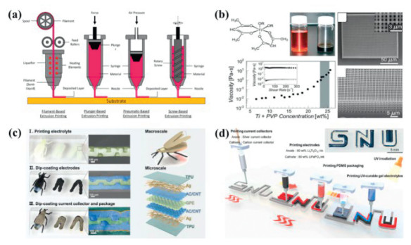
3D-printed, also known as additive manufacturing technology, has sparked increasing interest from industry and laboratories [123-126]. Unlike traditional subtractive manufacturing, 3D-printing can be digitally controlled to create three-dimensional objects. 3D-printed, as a novel manufacturing technology, has been applied in many fields, such as medical, industrial manufacturing, chemical engineering, aerospace, and automotive [127-129]. Recently, 3D-printed has also been used to manufacture energy storage devices, such as lithium batteries and capacitors [130-133]. It is believed that 3D-structured electrodes fabricated by 3D-printed technology have the advantages of shorting diffusion pathways and reducing resistance compared with 2D-structured batteries, which will improve battery energy density and power density indeed [134-136]. Besides, this latest technology provides a promising way to manufacture flexible and stretchable electrical devices. According to the different type of extruder used, 3D-printed can be divided into four categories: Filament-based extrusion, pneumatic-based extrusion, plunger-based extrusion, and screw-based extrusion (Fig. 7a). Wright et al. using a 3D-printed technique prepared a sandwich-type zinc battery, the ionic liquid and polymer were precisely deposited and patterned onto substrate to fabricate multilayer structured gel electrolyte [137]. The performances of micro-cells were discussed, the discharge capacity and energy density were recorded as 0.98 mAh/cm2 and 1.2 mWh/cm2 after 70 cycles, respectively. As known in the field, achieving certain complex 3D patterned architectures may require additional processing to achieve the desired functionality (Fig. 7b) [138, 139]. Zhou and colleagues first printed a 3D structured electrolyte template using interdigitated digital light processing [140]. A light-curable precursor was chosen to prepare GPE, which was composed of an ionic liquid, monomers, SiO2 nanoparticles, and a photo-initiator. The customization of the GPE was firstly printed through digital light processing, followed by dip coating with electrode, package, and current collector to assembly an energy storage device (Fig. 7c). The fabricated device with a highly 3D internal interdigitated structure enabled the device presented higher areal capacity than that of traditional planar configuration. They believe that electronics with highly 3D internal interdigitated structure are the key to achieving weight reduction and miniaturization. What is more, 3D-printed will open new approach to fabricate energy storage devices for wearable applications. Due to advanced digital printing technology, batteries with complex architectures and shapes can be produced. Viscoelastic polydimethylsiloxane and ethoxylated trimethylolpropane triacrylate were carried out to prepare GPE by 3D-printed and UV curing method (Fig. 7d) [141]. Electrodes and GPEs were tightly bonded without external pressure, and each component was successfully constructed, securing interface stability, diffusion kinetics, electrical connection, and cycling performance. As a result, the 3D-printed battery achieved a maximum areal loading of 25 mg/cm2.
Figure 7
Figure 7.
(a) Schematic diagram of filament-based extrusion printing, plunger-based extrusion printing, pneumatic-based extrusion printing, and screw-based extrusion printing. Reproduced with permission [130]. Copyright 2022, Elsevier. (b) Molecular structure of the titania-based precursor, where R represents CH(CH3)2. Optical image of the initial precursor and ink. Ink viscosity plots with different Ti + PVP concentration and shear rate. Scanning electron microscopy (SEM) image of the calcined TiO2 structure and a high magnification inset of this structure. Focused ion beam-milled cross-section of the oxide structure. Reproduced with permission [138]. Copyright 2017, Wiley-VCH. (c) The optical photographs and the false-colored cross sectional SEM images of the samples of 3D ESDs based on 3D printed GPE. Reproduced with permission [140]. Copyright 2023, Wiley-VCH. (d) The fabrication procedure of the scalable and shape-versatile all 3D printed LIBs using continuous direct ink writing. A photographic image of all 3D printed letter-shaped LIBs is also included in inset. Reproduced with permission [141]. Copyright 2023, Elsevier.
3.
Applications of GPEs in various configuration of LMBs
The development of flexible and stretchable metal batteries still remains some significant challenges. On the one hand, the electrode materials of battery are usually brittle and rigid, which cannot suffer large deformation [142-146]. On the other hand, it remains a giant challenge to maintain electrochemical performance of flexible and stretchable metal batteries under frequent mechanical strains [147-149]. The structural design provides a viable approach to achieve safety and stretchability LMBs without performance deterioration. Up to now, various shapes of deformable battery devices have been developed for improving the flexibility and stretchability of LMBs, such as sandwich-type, wire type, island-bridge type, and spring type [150-153].
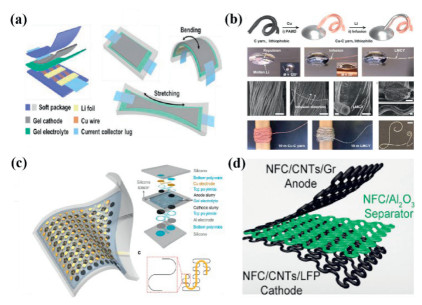
Sandwich-type LMBs with 2D planar structured are the most widely investigated configuration toward flexible and stretchable. This structure is composed of electrolyte membranes sandwiched between the anode and cathode [154-156]. The planar configuration is primarily discussed due to its ease of manufacture, excellent performance, and rapid ionic diffusion at the electrolyte-electrode interface. Jin demonstrated a super-stretchable Li−S battery composed of a highly elastic cathode, flexible gel electrolyte, Li pieces connected with zigzag Cu wire anode, and soft package (Fig. 8a) [157]. The homogeneously distributed 3D porous structure gave the cathode with excellent flexible and sulfur loading. The prepared GPE exhibited high ionic conductivity, flexibility, and mechanical strength. As a result, the packed Li‒S battery can be stretched up to 420% of their original length with an ultrahigh areal sulfur loading of 14 mg/cm2. Wang reported a convenient method to prepare a fully planar battery with high stretchability [158]. Intrinsically stretchable cathode and anode were prepared by electrostatically spraying the active materials on an elastic current collector. Meanwhile, a PVDF/TPU nanofiber was obtained as flexible separator using electrospinning technique. The fabricated cell presented stable electrochemical performance under frequent release-stretch testing, which reserved 70% of the initial capacity after 100 cycles.
Figure 8
Figure 8.
(a) Assembly of super stretchable Li‒S batteries with highly elastic composite gel cathodes, gel electrolytes, zigzag Cu wire-interconnected Li anode pieces, and elastic packages. Reproduced with permission [157]. Copyright 2021, Elsevier. (b) Fabrication and characterizations of lithium–metal composite yarn (LMCY). Schematic illustration of the fabrication of LMCY. Optical image of the C yarn after being put into the molten Li. Optical images of the infusion of molten Li into the Cu-C yarn. Morphology of Cu-C yarn. Morphological change of Cu-C yarn during the infusion process. Morphology of LMCY. A chemical symbol of "Li" made with flexible LMCY. Reproduced with permission [162]. Copyright 2021, Wiley-VCH. (c) The bio-inspired design and fabrication process of a rigid-supple integrated FLIB. The analogy from arrays of osteoderm arrangement in crocodile skin to FLIB design. The process to fabricate the rigid-supple integrated FLIB, long cut and stacked electrode sheet was sectionally folded and wound to form two-dimensional rigid-supple shape, then the whole cell was sealed by Al-plastic films in a vacuum. Reproduced with permission [170]. Copyright 2022, Elsevier. (d) Compositional and morphological features of the ink for 3D printing of the stretchable battery components. Reproduced with permission [176]. Copyright 2022, Elsevier.
To date, wire type or fiber type batteries, as a fascinating power source, are receiving growing interest in field of wearable and portable electronics. Different from planar type devices, wire type batteries can deliver stable energy under complex deformations, including bending, twisting, tangling, folding, and stretching (Fig. 8b) [159-162]. Wire-shaped lithium-ion batteries and zinc-ion batteries have gained significant development during the past two decades, but few studies on of wire type LMBs have been reported in the literatures. LMBs with high theoretical capacity and the lowest electrochemical potential have great potential to meet the energy demand of wire type energy storage devices [163]. A quasi-solid-state wire-shaped Li–CO2 battery was demonstrated by Wang et al. to address the poor stability, low energy density, and leakage of flexible LMBs [164]. A GPE was prepared by UV-cured of PVDF-HFP and trimethylolpropane ethoxylate triacrylate. Simultaneously, lithium wires were dipped in the GPE precursor mixture to guarantee that the lithium wires were complete covered by GPE. The fabricated wire-shaped Li–CO2 battery exhibited stability working under various deformation states. The interface problems of flexible batteries are more complex. The electrodes and electrolytes of flexible batteries may separate during repeated folding, bending, and stretching processes, resulting in poor electrochemical properties. Recently, Peng's group developed a new strategy to prepare high-performance fiber lithium battery [165]. Firstly, they rotated cathode fibers and anode fibers together to form aligned channels. After that, the monomer solution was effectively infiltrated along the channels. Finally, a GPE was produced by in-situ polymerization of the monomers. The GPE had closely and stably interfaced with the electrode fibers, resulting in low interfacial resistance. The discharge capacity of the battery was nearly five times greater than that of the traditional fiber battery at 2 C. The battery with high capacities could be woven into a large-area power textile and worked safely under extreme conditions.
Island-bridge type represents another classical configuration for flexible and stretchable energy storage devices [166-169]. These configurations consist of rigid island regions and soft bridges. The rigid regions contain active materials and are regularly dispersed on an elastomeric substrate, resembling islands. Meanwhile, each rigid regions are interconnected through flexible conductors. In this structure, the conductors function as bridges to maintain electrical conductivity under mechanical deformations, while the elastomeric substrate endows the devices with excellent flexibility and extensibility. A typical island-bridge stretchable batteries was displayed by Rogers's group (Fig. 8c) [170]. They fabricated stretchable batteries by arraying of small-scale unit cells on low modulus silicone elastomer substrate, which were interconnected by conducting frameworks. The testing results revealed that the obtained stretchable batteries enabled biaxial stretchability up to 300% and displayed an area capacity density of 1.1 mAh/cm2 even under deformations. Zhang et al. reported a novel battery architecture inspired by bamboo slips for the preparation of a flexible and wearable device [171]. The Li-O2 soft batteries were packaged by lithium belt anode, LiCF3SO3 in TEGDME as GPE, glass fiber separator, and P coated carbon textiles as air cathode. After that, the fabricated batteries were cross-woven together to form a slip like textile, which was capsulated with adhesive tapes to obtain a flexible and wearable device. This flexible and wearable Li-O2 batteries presented steady electrochemical performances (such as specific capacity, energy density, rate capability, and long-term cycling) under various deformations.
Spring-structured LMBs provide a simple and effective way to realize mechanical flexible and stretchable energy storage devices [172-174]. Spring-structured flexible devices reduce the requirement for inherently flexible materials through structural design. The preparation of spring-structured electrodes is the key to achieve the structurally stretchability. Cui and coworkers used a novel hierarchical Cu coiled embedded with Li metal to prepare highly elastic Li metal anode [175]. The Li metal was divided into small microdomains by elastic rubber matrix. It was found that the rubber elastomer absorbed most of the mechanical strain, allowing the Li metal microdomains to experience little mechanical stress with no deformation. As a result, this 3D-patterned Li metal anode composed of the 2D Cu coil and rubber elastomer, addressed the high modulus issue of metal materials, leading to excellent electrochemical cycling stability under stretching. This is an interesting configuration that makes a trade-off between the electrochemical performances and stretchability of the Li metal anode, provides a facile and cost-effective process for flexible and stretchable LMBs. 3D printing has drawn increasing interest for producing complex 3D objects in recent years. A facile yet effective approach was demonstrated to prepare highly elastic spring electrodes and GPE for flexible and stretchable batteries by 3D printing technology (Fig. 8d) [176]. The resulting serpentine-patterned electrodes and GPE separator exhibited excellent elasticity with a reversible stretchability of 50%. Moreover, the 3D printing electrodes were electrochemical stability, which the resistance only increased by 3% after repeating stretching for 50 times. Following 50 cycles of repeat stretching, the spring-structured electrodes and GPE separator were utilized to fabricate CR2032-type coin cells. The cells demonstrated a maintained capacity of 355 mAh/g after discharge–charge process for 100 cycles. In a word, 3D printing provides a facile and cost-effective manufacturing process in the preparation flexible and stretchable LBMs.
4.
Functional GPEs for safe LMBs
The criteria of an appropriate GPE for LMBs should accommodate high ionic conductivity and electrochemical stability, high Young's modulus, strong interaction with electrolytes, and the ability to restrict polysulfide shuttle. As applications for wearable electronics, the growing intimacy between batteries and the human body calls for improved security urgently. Safety risks remain a fundamental hazard on the practical application of flexible and stretchable LMBs. In addition to the properties mentioned above, GPEs with multifunctional such as self-healing, nonflammable, and temperature tolerance are arousing people's continuous attention. The specific properties and functionalities of GPEs will improve the safety and largely extend the applied ranges of LMBs in various fields.
4.1
GPEs with self-healing
Although remarkable progress has been achieved in the practical application of flexible and stretchable LMBs, several remaining hurdles must be considered. For example, tiny defects will emerge when GPEs endure repeatable deformation under bending, folding, and stretching state, resulting in complete breaking after long-term working, threatening the performance and lifespan of the LMBs. Self-healing materials, capable of spontaneously repairing internal or external damages, represent another desirable property of GPEs for the next generation of flexible and stretchable LMBs. GPEs with self-healing capabilities will enhance safety and prolong the lifespan of batteries.
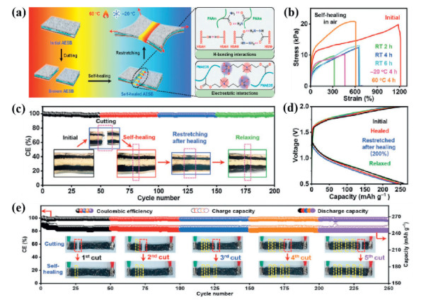
Generally, reversible covalent bonds or supramolecular chemistry are adopted mostly to realize intrinsic self-healing materials [177-184]. Ion–dipole interaction is a kind of dynamic bonds, which is a force between charged ions and polar molecules. Wang et al. reported the preparation of stretchable, transparent, and self-healing ionic conductor utilizing ion–dipole interactions for the first time [185]. The ionic conductor was a composite of PVDF-co-HFP (PVDF-co-HFP-5545, which polymer contains a much higher HFP component of 45%) and 1-ethyl-3-methylimidazolium trifluoromethanesulfonate. PVDF-co-HFP with a very high dipole moment of 5.507 Debye, had a strong ion-dipole interaction with the IL, restricting IL leakage from the material. As a result, this novel material can undergo an extreme strain exceeding of 5000%. The ionic conductor performed a high ionic conductivity of 10−4 S/cm and excellent transparency up to an average transmittance of 92%. More importantly, the material can be completely recovered to its original mechanical properties within 24 h, showing outstanding self-healing capabilities. For LMBs, fast self-healing is imperatively needed to avoid short circuit happening. Fast self-healable solid polymer electrolytes (SHSPEs) were prepared through the mixture of NH2-PEG-NH2, TPU, IPDI, and liquid electrolytes in chloroform [186]. The SHSPEs were obtained after removing the solvent. The urea groups of TPU cross-linked to the ester groups of the PEG, generated physical crosslinker points that improved the mechanical strength of the SHSPE by hydrogen bonding. Therefore, the dynamic and reversible intermolecular or intramolecular hydrogen bonding in the polymer chains contributed to the fast self-healing ability of the SHSPEs, allowing them to completely self-heal within 60 s after damage. However, most self-healing gels exhibit poor mechanical properties. Developing GPEs with excellent mechanical performance and fast self-healing property at room temperature is still a great challenge. Simultaneously integrating multiple interactions may resolve this challenging issue. Long et al. synthesized a novel high mechanical strength and self-healing ion gel by triple-network [187]. This self-healing ion gel comprised PVA, PAA, PAM, sustainable cellulose nanocrystals, graphene oxide, and ILs. The triple-network resulted from the hydrogen bonds between polymers, hydrogen bonds between polymers and inorganic fillers, and ionic bonds between polymers and ILs. The obtained ion gel exhibited more excellent mechanical properties up to 15.9 MPa, excellent elongation at a 610% break. More important, the ion gel can recover 90% of the initial mechanical properties after healing for 24 h in air without any external force. An all-eutectogel stretchable battery was reported by Liu et al. which simultaneously exhibited full-cell self-healing and stretchability [188]. Zwitterionic poly[2-(methacryloyloxy)ethyl]diethy-(3-sulopropyl) was selected as the gelation substrate for GPE. In addition, a small fraction of (R)−12-hydroxystearic acid was added as a hydrazide supramolecular gelator to further enhance the strain performance of GPE by the existence of supramolecular-polymer double-network structure (Fig. 9a). The fabricated battery recovered a fracture strain of 650% and a self-healing efficiency of 55% at room temperature for 4 h (Fig. 9b). The battery presented excellent self-healing, almost completely recovery to the initial capacity of 248.15 mAh/g and a high Coulombic efficiency of 100% (Figs. 9c and d). Finally, the battery suffered from five cutting-healing cycles at the same position maintained high capacity and nearly 100% coulombic efficiency (Fig. 9e), meaning that this self-healing all-eutectogel system was suitable for flexible and stretchable energy storage devices.
Figure 9
Figure 9.
(a) Design and performance of full-device autonomous self-healing and omnidirectional intrinsically stretchable all-eutecto gel soft battery (AESB). HSAH: (R)-12-hydroxystearic acid hydrazide; PAAm: polyacrylamide; DES: deep eutectic solvent; PMAEDS: poly[2-(methacryloyloxy)ethyl] diethy-(3-sulopropyl); CNT: carbon nanotube. (b) Tensile test of AESB at different temperatures. (c) Cyclic performance of AESB at 0.1 A/g under various areal strains. (d) Discharge and charge voltage profiles of AESB at 0.1 A/g under various areal strains. (e) The capacity and the coulombic efficiency of AESB restored after five repeated cutting-healing cycles. Reproduced with permission [188]. Copyright 2022, Wiley-VCH.
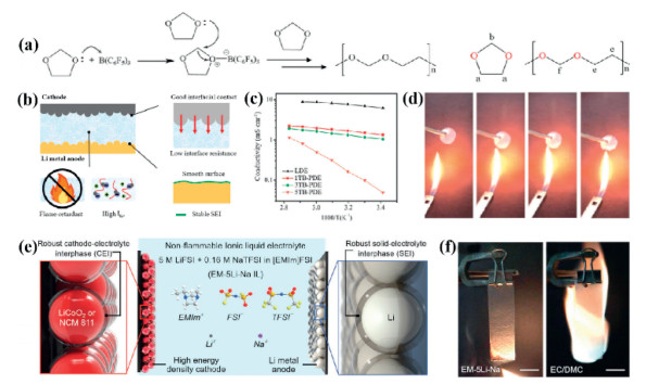
Flammability is another unsatisfactory performance of LMBs, posing serious safety concerns. Conventional liquid organic electrolytes including ethylene carbonate (EC), dimethyl carbonate (DMC), diethyl carbonate (DEC), ethyl methyl carbonate (EMC), and propylene carbonate (PC) are highly flammable, which may trigger fire accident if an internal short circuit occurs. Blending standard electrolytes with flame-retardant additives provides an efficient and effective strategy to address this intractable safety issue. For instance, Huang and coworkers pursued a multifunctional tris(pentafluorophenyl)borane (TB) to prepare 1, 3-dioxolane electrolyte (PDE) by in-situ polymerized [189]. TB acted as both a polymerization initiator and a flame retardant (Fig. 10a). They discovered that PDE prepared by in-situ polymerization provided the integrated battery with a stabilized electrode–electrolyte interface and achieved excellent flame retardant (Figs. 10b and d). The ionic conductivities of PDEs with different contents of TB from 20 ℃ to 80 ℃ were shown in Fig. 10c. 1TB-PDE and 3TB-PDE preformed outstanding ion conduction, with ionic conductivities of 1.502 mS/cm and 1.163 mS/cm at room temperature, respectively. The fabricated Li–S batteries demonstrated satisfactory cycle stability (4500 cycles) and excellent electrochemical performance over a wide operating temperature range, offering a promise approach for designing reliable LMBs. Tris(2, 2, 2-trifluoroethyl) phosphite, triethyl phosphate, fluoroethylene carbonate, and trimethyl phosphate (TMP) as flame retardant have been used to enhance both safety and electrochemical performance of liquid electrolytes for LMBs in recently years [190-196]. Among of which, TMP, with a high dielectric constant (ɛ = 21), low viscosity (2.32 mPa s), and wide liquid temperature window (−46~197 ℃), is widely used for nonflammable batteries. The addition of phosphorus-rich compounds improved the flame-retardant properties but had very little effect on the ionic conductivity of the electrolytes. As a result, the prepared Li-S battery exhibited a high Coulombic efficiency above 99% even at high temperature. Ciucci et al. displayed a new nonflammable quasi-solid electrolyte (QSE) prepared by in-situ polymerization and incorporated with TMP, rendering the electrolyte nonflammable [197]. The nonflammable of GPE was carried out by the electrolyte in flame with butane as fuel. The Li|QSE|LiFePO4 cell displayed a specific discharge capacity of 166 mAh/g at 0.2 C and 153 mAh/g at 1 C, with excellent capacity retention of 94% at 0.5 C for 500 cycles. It powered an LED light to show the flexibility and safety of the battery. ILs are potential candidates as non-flammable alternatives to carbonate-based electrolytes for high-safety batteries. They are intrinsic nonflammability, nonvolatile, and ionic conductive. However, the high viscosity of ILs leads to low cathode load, which limits their application in high energy density batteries. Sometimes, people use ILs as additives to improve the flame retardation performance of conventional electrolyte. This paves the way of the practical application of ILs. Very recently, Dai and his coworkers presented a novel low viscosity ILs electrolyte for high-safety and high-energy-density LMBs. This ILs electrolyte (named EM–5Li–Na IL) was comprise of 1-ethyl-3-methylimidazolium bis(fluorosulfonyl)imide ([EMIm]FSI) with 5 mol/L lithium bis(fluorosulfonyl)imide (LiFSI) and 0.16 mol/L sodium bis(trifluoromethanesulfonyl)imide (NaTFSI) as additives (Fig. 10e) [198]. The EM–5Li–Na IL exhibited low viscosity at room temperature, approximately half that of Py13-based ILs. NaTFSI participated in the formation of SEI and contributed to Li deposition. Flammability tests indicated that the EM–5Li–Na IL electrolyte had superior nonflammability compared to conventional organic electrolyte (Fig. 10f). Thanks to the low viscosity of EMIm-cation-based ILs, the EM–5Li–Na IL showed a satisfactory ionic conductivity of 2.6 mS/cm at room temperature, which was important to realize high specific capacity and high mass cathodes loading. Li|EM–5Li–Na IL|LiCoO2 batteries presented high specific capacity (199 mAh/g) and energy density (765 Wh/kg) at 0.7 C, along with impressive cycling performance of 1200 cycles. Surface X-ray photoelectron spectroscopy, SEM, scanning transmission electron microscopy, high-angle annular dark-field, and time-of-flight secondary ion mass spectrometry were employed to verify the important role of NaTFSI in the stabilization of the electrode/electrolyte interphase. It was found that a trace of Na+ took part in the formation of the hybrid passivation layer on the surface of electrodes could promote lithium-ion conduction, suppress Li dendrite, and prevent side reaction between electrodes and electrolyte. These findings strongly supported to prepare LMBs with nonflammable, high safety, high-energy-density, and long lifespan. Besides, attaching flame-retarding moiety (such as phosphonate and ionic groups) to polymer skeleton by chemical bonds provides another way to fabricate nonflammable gel polymer electrolyte [199].
Figure 10
Figure 10.
(a) Schematic diagram of the polymerization mechanism of PDE. Structure formulas of DOL and poly-DOL. (b) Schematic diagram of PDE with high ionic conductivity, stable SEI, good interfacial stability, and flame-retardant. (c) Temperature-dependent ionic conductivity of LDE, 1TB-PDE, 3TB-PDE, 5TB-PDE, respectively. (d) Flame test of the separator with PDE infiltration. Reproduced with permission [189]. Copyright 2021, Royal Society of Chemistry. (e) Schematic illustration of the battery configuration and electrolyte composition of the EM–5Li–Na IL electrolyte. (f) Flammability tests of the EM–5Li–Na IL electrolyte and conventional organic electrolyte consisting of 1 mol/L LiPF6 in EC/DMC. Reproduced with permission [198]. Copyright 2020, Wiley-VCH.
The utilization of conventional carbonate electrolytes may pose another potential threat due to their poor cell performance and safety issue under high temperature [200]. The capacity of cells with carbonate electrolytes rapid fading above 55 ℃ due to the decomposition of the electrolyte [201, 202]. If the temperature exceeds 69 ℃, the solid electrolyte interphase will decompose and self-accelerate the side reaction between the electrolytes and the anode, deteriorating the lifespan of batteries. Additionally, the shrinkage and melting of the separator at high temperatures may induce short circuits, resulting in significant safety hazards. Therefore, the innovation of components of LMBs at elevated temperature is urgently needed to address these safety issues.
One practice strategy is to enhance the interaction between Li salts, solvents, and the polymer matrix. Ciucci et al. presented a dual-salt polymer electrolyte, consisting of polymer matrix (PVDF), coordinated solvents (DMF, FEC, EC, and PC), and thermally stable Li-salts (LiTFSI and LiBOB) [203]. The developed dual-salt polymer electrolyte performed high ionic conductivity over an extended temperature range. As a result, the fabricated LMBs delivered excellent temperature tolerance and cycling stability (500 cycles) at 0.5 C from −10 ℃ to 80 ℃. Replacing low boiling/flashing point electrolytes (such as EMC, DMC, and DEC) with high thermal stability electrolytes is an effective strategy to satisfying battery performance. SN is a solid plastic crystal with high boiling point (267 ℃) and low flammability which is a candidate for high temperature electrolyte [204]. SN-based electrolyte is infiltrated into a UV-cured cross-linked polyurethane acrylate skeleton to prepare a GPE. This GPE exhibits a high ionic conductivity (1.63 × 10⁻³ S/cm at 25 ℃), and the fabricated LiCoO2|GPE|Li cell shows stable charge−discharge cycle at high temperature (55 ℃). For decades, the investigation of supramolecular has drawn increasing attention in academia and industry. Supramolecular interactions including reversible non-covalent interactions such as π-π stacking interaction, hydrogen bonding, metal-ligand coordination, and host-guest recognition. A GPE film comprised of a supramolecular network structure was designed and developed to fulfill the thermal stability and mechanical property demands [205]. The resulting GPE possessed a high ionic conductivity (3.8 × 10⁻³ S/cm at room temperature) and high electrochemical window (≥4.6 V). ILs with high thermal stability can be used to high temperature electrolytes, too. For instance, an exciting IL (N-ethyl-N-methylpyrrolidinium bis(fluorosulfonyl)imide, P12FSI) was introduced into the pyrrolidinium-based poly(ionic liquid) /LiTFSI system to prepare a novel PIL–P12FSI–LiTFSI electrolyte [206]. The electrolyte had an ionic conductivity above 10–4 S/cm at room temperature, along with high thermal and electrochemical stability. The assembled cell exhibited high discharge capacity and excellent lifespan at a broad operating temperature range (25–80 ℃). Li et al. introduced ionic liquid N-methyl-N-propyl-pyrrolidinium bis(-fluorosulfonyl)imide (Pyr13FSI) into a cross-linked network to prepare GPE [207]. The GPE exhibited not only high ionic conductivity (1 mS/cm) but also an excellent operating temperature range of up to 90 ℃. Boron nitride nanosheets (BNNSs) were cast onto the surface of PP separators (PP-BNNSs) for Li-S batteries [208]. Compared with pristine PP separator, the PP-BNNSs presented excellent thermal stability. The PP separator was complete crimped, whereas the PP-BNNS separator remained intact under a hot plate at 80 ℃. Therefore, the BNNSs modified PP separator is expected to be applied to high temperature and long lifespan Li-S batteries. GPEs with smart temperature-responsive opens up new vision to develop safe LMBs.
5.
Conclusion and outlook
Smart and wearable electronics will change people's daily life in the future significantly. Energy Storage devices with flexible, bendable, foldable, and stretchable are urgently required. LMBs, which possess an unprecedented high theoretical capacity favorable for device miniaturization, are highly desirable for the next-generation flexible and stretchable battery systems. However, there are several major concerns that limit the practical applications of flexible and stretchable LMBs. The development of high performance GPEs is a key impetus for LMBs. GPEs combine the advantages of liquid electrolytes, which have high ionic conductivity, with those of soft polymers, which can undergo deformation without performance deterioration. This brief review summarizes the recent progress in the preparation of GPEs, such as casting method, phase-inversion method, sol-gel processing, electrospinning, in-situ polymerization method, and 3D-printed technology. For example, the casting method offers a facile and cost-effective approach to preparing GPEs, particularly for composite materials. GPEs are high ionic conductivity but usually suffer from poor mechanical strength. The addition of inorganic fillers can significantly improve the mechanical properties of GPEs without weakening other properties. The enhanced mechanical properties can effectively inhibit the growth of lithium dendrite and enable GPEs to withstand violent forces without damage. Electrospinning method can prepare GPEs with porous nanostructure and excellent stretchability. Thanks to the ultrahigh porosity, GPEs prepared by electrospinning can load more liquid electrolytes, resulting in high ionic conductivity and an elevated Li+ transference number. The in-situ polymerization method can produce GPEs with excellent interfacial compatibility with electrodes, thereby decreasing charge transfer resistance. The formation of a cross-linked structure gives GPEs with a high toughness value, making them promising candidate for flexible and stretchable LMBs batteries. Furthermore, the in-situ gelation process contributes to forming a robust SEI/CEI on the anode/cathode surface, which helps suppress Li dendrite growth during the stripping/plating.
Structural strategies (such as sandwich structure, wire structure, island-bridge structure, and spring structure) are the key technologies for the application of flexible and stretchable LMBs. Adopting the state-of-the-art manufacturing technologies such as 3D-printed and other additive manufacturing methods, to develop innovative battery configurations may provide the optimal paradigm for achieving flexible and stretchable LMBs.
In addition to the properties mentioned above, other smart functionalities for GPEs, such as self-healing, nonflammability, and temperature tolerance, are needed to further expand the application range of LMBs. Self-healing GPEs can heal the damaged interfaces by reversible covalent bonds or supramolecular chemistry. Energy storage devices with self-healing are particularly useful for wearable electronic. Conventional liquid organic electrolytes are highly flammable, which may trigger fire accidents if an internal short circuit occurs. Scientists develop nonflammable LMBs by adding flame retardant or using ILs instead of traditional liquid electrolytes, thereby reducing potential losses when accidents occur. To enhance the temperature tolerance of GPEs, thermal stability plasticizers or inorganic fillers are introduced into the GPEs system, improving the security of LMBs under high temperature.
Moreover, environmental impact of GPEs has drawn increasing attention in recent years. Most commercial polymer skeletons are synthesized from non-renewable petroleum-based materials, such as PVDF, PMMA, PEO, and PP. These petroleum-based polymers are hard to disposal and non-recyclable, which would cause white pollution, threatening people health and the environment. Green and renewable biopolymers are carried out to prepare GPEs to solve this issue. Natural polymers like cellulose, chitosan, alginate and so on with outstanding biocompatibility and biodegradability are employed for preparing GPEs. However, the practical applications of these polymers in commercial batteries still have a long way to go. The electrochemical/thermal stability, the mechanical strength, and the durability of biopolymer should be improved to prolong the lifespan of batteries.
Last but not least, compared with flexible and stretchable LIBs and supercapacitors, flexible and stretchable LMBs are still in their infancy. Although a lot of efforts have been made to develop high performance GPEs for flexible and stretchable LMBs, there is still a long run need to go before their practical application is feasible. For example, considerable amounts of electrolytes are needed to realize high ionic conductivity of GPEs, which brings security risk; ILs, used instead of conventional liquid carbonate electrolytes, are expensive; the safety issue of LMBs remains unsolved for their practical application. Future demand will impel the development of GPEs with high ionic conductivity, excellent mechanical properties, electrochemical and thermal stability, and that are flexible, stretchable, and cost-effective. Recent research has shed light on the evolutionary direction, and will eventually develop high performance GPEs for flexible and stretchable LMBs.
Declaration of competing interest
The authors declare that they have no known competing financial interests or personal relationships that could have appeared to influence the work reported in this paper.
Figure 1
Schematic illustration and performance comparisons of (a) the liquid electrolyte, (b) gel polymer electrolyte, and (c) solid-state electrolyte. Reproduced with permission [40-42]. [40] Copyright 2020, Wiley-VCH. [41] Copyright 2022, American Chemical Society. [42] Copyright 2017, Springer Nature.
Figure 2
Synthesis and properties of PVFH-TOC-PEG GPE. (a) Schematic illustration for the synthesis of the PVFH-TOC-PEG electrolyte. (b) Photograph image of the PVFH-TOC-PEG membrane. (c) SEM image of PVFH-TOC-PEG membranes. (d) The PVFH-TOC-PEG electrolyte pressed with a metal bar and stress-strain measurement of the PVFH-TOC-PEG membrane. (e) Polysulfide permeation tests for the GPE. (f) Stress-strain curves of the PVFH-based membranes. (g) Cycling performance of the GPE Li-S cells at 8 mA/cm2. (h) Flexible S|PVFH-TOC-PEG|Li battery evaluated under different conditions. Reproduced with permission [72]. Copyright 2020, Royal Society of Chemistry.
Figure 3
(a) Schematic of the intermolecular hydrogen binding effect between PVDF-HFP, PEO, and GO in the PHPG polymer, and schematic of the 3D porous polymer network of PHPG formed by the intermolecular hydrogen binding effect. (b) Charge/discharge curves of the PHPG-DIB at the 10th, 500th, 1000th, 1500th, and 2000th cycle at 5 C. (c) Average discharge voltage of the PHPG-DIB at 5 C over 2000 cycles. (d) Cycling performance of the flexible PHPG-DIB under flat, curling, and folding state at 2 C. Reproduced with permission [88]. Copyright 2018, Wiley-VCH. (e) Process of the borate-based porous polymer electrolyte. (f) SEM image of the borate-based porous polymer electrolyte membrane. (g) Cycling performance of fabricated LFP/Li cells using the borate-based porous polymer electrolyte at 0.2 C. Reproduced with permission [91]. Copyright 2021, American Chemical Society.
Figure 4
Preparation of the poly-DOL GPE. (a) Schematic illustrations of a synergetic strategy of in-situ synthesis of a GPE and pretreatment on Li metal. Reproduced with permission [100]. Copyright 2020, American Chemical Society. (b, c) The schematic diagrams of Si nanoparticles inhibiting the growth of lithium dendrites. (d) Cycling performances at 1 C of untreated/pretreated-Li|GPE|LiFePO4 batteries. Reproduced with permission [102]. Copyright 2020, American Chemical Society.
Figure 5
(a) Controllable fabrication of PI NF films with a sol-gel electrospinning followed by a step heating. (b) Thermal shrinkage behaviors of the PIQSE and PPQSE films at 50 ℃ for 2 h, 120 ℃ for 2 h, and 160 ℃ for 2 h. (c) Long-cycling behavior of the quasi-SSLBs with LiFePO4 cathodes at 0.5 C. (d) Surface morphological changes of Li-anodes after 500 h in the symmetric cells with PPQSE and PIQSE. Reproduced with permission [112]. Copyright 2022, Wiley-VCH.
Figure 6
(a) Schematic diagram of the synthesis process of the block PLE precursor powders and the 3D PALE GPEs. Reproduced with permission [121]. Copyright 2023, Wiley-VCH. (b) The schematic illustration of the preparation of the functionalized PI@F-PMIA separator and the resulting battery assembling process. (c) The long-life cycle test and the Coulombic efficiency at 0.5 C and of the lithium-metal cells with Celgard, PI, F-PMIA, and PI@F-PMIA separators. Reproduced with permission [122]. Copyright 2021, Elsevier.
Figure 7
(a) Schematic diagram of filament-based extrusion printing, plunger-based extrusion printing, pneumatic-based extrusion printing, and screw-based extrusion printing. Reproduced with permission [130]. Copyright 2022, Elsevier. (b) Molecular structure of the titania-based precursor, where R represents CH(CH3)2. Optical image of the initial precursor and ink. Ink viscosity plots with different Ti + PVP concentration and shear rate. Scanning electron microscopy (SEM) image of the calcined TiO2 structure and a high magnification inset of this structure. Focused ion beam-milled cross-section of the oxide structure. Reproduced with permission [138]. Copyright 2017, Wiley-VCH. (c) The optical photographs and the false-colored cross sectional SEM images of the samples of 3D ESDs based on 3D printed GPE. Reproduced with permission [140]. Copyright 2023, Wiley-VCH. (d) The fabrication procedure of the scalable and shape-versatile all 3D printed LIBs using continuous direct ink writing. A photographic image of all 3D printed letter-shaped LIBs is also included in inset. Reproduced with permission [141]. Copyright 2023, Elsevier.
Figure 8
(a) Assembly of super stretchable Li‒S batteries with highly elastic composite gel cathodes, gel electrolytes, zigzag Cu wire-interconnected Li anode pieces, and elastic packages. Reproduced with permission [157]. Copyright 2021, Elsevier. (b) Fabrication and characterizations of lithium–metal composite yarn (LMCY). Schematic illustration of the fabrication of LMCY. Optical image of the C yarn after being put into the molten Li. Optical images of the infusion of molten Li into the Cu-C yarn. Morphology of Cu-C yarn. Morphological change of Cu-C yarn during the infusion process. Morphology of LMCY. A chemical symbol of "Li" made with flexible LMCY. Reproduced with permission [162]. Copyright 2021, Wiley-VCH. (c) The bio-inspired design and fabrication process of a rigid-supple integrated FLIB. The analogy from arrays of osteoderm arrangement in crocodile skin to FLIB design. The process to fabricate the rigid-supple integrated FLIB, long cut and stacked electrode sheet was sectionally folded and wound to form two-dimensional rigid-supple shape, then the whole cell was sealed by Al-plastic films in a vacuum. Reproduced with permission [170]. Copyright 2022, Elsevier. (d) Compositional and morphological features of the ink for 3D printing of the stretchable battery components. Reproduced with permission [176]. Copyright 2022, Elsevier.
Figure 9
(a) Design and performance of full-device autonomous self-healing and omnidirectional intrinsically stretchable all-eutecto gel soft battery (AESB). HSAH: (R)-12-hydroxystearic acid hydrazide; PAAm: polyacrylamide; DES: deep eutectic solvent; PMAEDS: poly[2-(methacryloyloxy)ethyl] diethy-(3-sulopropyl); CNT: carbon nanotube. (b) Tensile test of AESB at different temperatures. (c) Cyclic performance of AESB at 0.1 A/g under various areal strains. (d) Discharge and charge voltage profiles of AESB at 0.1 A/g under various areal strains. (e) The capacity and the coulombic efficiency of AESB restored after five repeated cutting-healing cycles. Reproduced with permission [188]. Copyright 2022, Wiley-VCH.
Figure 10
(a) Schematic diagram of the polymerization mechanism of PDE. Structure formulas of DOL and poly-DOL. (b) Schematic diagram of PDE with high ionic conductivity, stable SEI, good interfacial stability, and flame-retardant. (c) Temperature-dependent ionic conductivity of LDE, 1TB-PDE, 3TB-PDE, 5TB-PDE, respectively. (d) Flame test of the separator with PDE infiltration. Reproduced with permission [189]. Copyright 2021, Royal Society of Chemistry. (e) Schematic illustration of the battery configuration and electrolyte composition of the EM–5Li–Na IL electrolyte. (f) Flammability tests of the EM–5Li–Na IL electrolyte and conventional organic electrolyte consisting of 1 mol/L LiPF6 in EC/DMC. Reproduced with permission [198]. Copyright 2020, Wiley-VCH.

 DownLoad:

 下载:
下载:


 下载:
下载:
