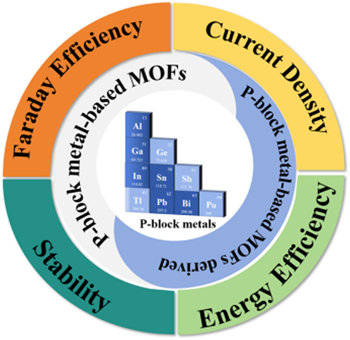
Scheme 1.
p-block metal-based MOFs and MOF-derived materials as CO2RR electrocatalysts.
Recent advances of metal-organic frameworks and MOF-derived materials based on p-block metal for the electrochemical reduction of carbon dioxide
Xinyu Wu , Jianfeng Lu , Zihao Zhu , Suijun Liu , Herui Wen

Since the Industrial Revolution, the rapid consumption of fossil fuels such as coal, oil, and natural gas, which have been the main sources of energy for human development, has led to large amounts of CO2 emissions [1-5]. Excess CO2 emissions have led to a disruption of the natural balanced carbon cycle, resulting in increasing CO2 concentrations in the atmosphere [6]. In addition, the atmospheric CO2 concentration is expected to reach a peak of 850 ppm by the end of this century [7,8]. As a greenhouse gas, the rising concentration of CO2 will lead to a range of global environmental problems, such as the greenhouse effect, ocean acidification, and extreme weather [9,10]. As a result, there is a growing awareness that the removal of excess carbon dioxide has become an urgent issue for environmental protection and sustainable development.
To mitigate these negative effects of excess CO2 emissions, various types of capture, storage, and conversion strategies have been developed in recent years [11-13]. The common ways to capture CO2 include gas separation [14], chemical adsorption [15], and physical adsorption [16]. However, the capture of CO2 not only consumes a lot of energy and costs but also easily reaches the capacity limit [17]. From another perspective, CO2 is the cheapest and most abundant non-toxic C1 source and has been regarded as a potential raw material for industrial production of high-value organic compounds or petroleum substitutes [18-20]. Therefore, chemical conversion is an ideal strategy for both reducing atmospheric CO2 concentrations and producing many valuable chemicals such as carbon monoxide, methane, formate, ethane, and ethylene [21-24]. There are many methods for the chemical conversion of CO2, and extensive studies have been conducted in the past few decades, including biochemical catalysis [25], chemical reforming [26], photocatalysis [27], and electrocatalysis [28], all of which exhibit promising potential in this field [29]. However, the efficiency, selectivity, and stability of the reaction are still difficult to ignore on the avenue to practical applications [30-39].
Among the above conversion methods, electrochemical CO2 reduction reaction (CO2RR) has become a valuable research topic all over the world due to its unique advantages such as mild conditions, simple device, and variety of products [40,41]. Especially with the increasing availability of renewable electricity, the economic viability of CO2RR is growing by the day [42]. The CO2RR system consists of a reaction device, electrolyte, and catalyst, of which the catalyst is the focus of the research [43,44]. To date, a variety of catalysts including metal alloys [45], metal oxides [46], metal sulfides [47], single atoms [48], metal complexes [49], metal-organic frameworks (MOFs) [50], and non-metallic materials [17] have been explored for their potential in the field of CO2RR. Among them, MOF catalysts are one of the most prospective heterogeneous catalysts due to their unique characteristics. MOF is a kind of porous material composed of metal ions or clusters coordinated with organic ligands [51-53]. It has multiple adjustable structural characteristics, such as porous structure, high specific surface area, diverse catalytic active sites, and adjustable structures [54-59]. The designability of MOFs provides a platform to modify their physical and chemical properties by tuning the composition, metal nodes, and organic ligands at the molecular level. MOFs with specific structures can be prepared using methods including pre-assembly and post-modification to create the desired functional materials [60]. In addition, the higher structural stability and recyclability of MOFs allow them to be used as heterogeneous catalysts, which is beneficial for separation and recycling after reaction [61]. More importantly, the well-defined crystal structure and active sites of MOFs contribute to the in-depth investigation of the reaction mechanism. Since 2012, MOFs have been used to catalyze CO2RR for the first time, and related research has grown exponentially in recent years [62,63].
Recently, p-block metal-based MOF materials have been shown to possess unique advantages in MOF catalysts [40]. The p-block metals, including Al, Bi, Sn, In, and so on, have unique electronic configurations from ns2np1 to ns2np6, endowing them with high electronegativity and low ionization energies. In the field of CO2RR, MOF materials based on p-block metals have high selectivity for C1 products, especially formate, which is usually much higher than reported non-metallic carbon-based catalysts [64-66]. The potential of p-block metal-based MOF materials in converting CO2 to formate makes them widely applicable [67]. Among the products of CO2RR, formate has a high economic value with a broad market demand, as well as the highest energy utilization per unit [68]. In addition, formate also has the characteristic spatial structure of aldehydes, indicating that formate also has a certain degree of reducibility, making it a highly valuable organic acid in industrial applications [69]. Therefore, it is crucial to explore the potential reaction mechanism and structure-activity relationship of p-block metal-based MOF materials in CO2RR, which will effectively guide the design of efficient catalysts for industrial applications (Scheme 1).
In this article, we will summarize the latest research progress and development status of p-block metal-based MOF electrocatalysts for CO2RR. Although there have been some reviews that comprehensively summarize the application of p-block metal-based electrocatalysts in CO2RR, our focus is to exemplify p-block metal-based MOF materials used as electrocatalysts, especially for electrocatalysts with high selectivity for formate. This review will offer a comprehensive overview of the recent advances in the field of p-block metal-based MOF catalysts for CO2RR. Furthermore, we will focus on catalyst modification methods and the relationships between structure performance. Finally, we will briefly discuss the challenges faced by this type of MOF-based materials and explore strategies to enhance catalytic performance in CO2RR, including structural changes, defect engineering, and doping strategies. We hope this review will contribute valuable theoretical guidance for the development of efficient catalysts to facilitate the practical application of CO2RR.
According to the molecular orbital theory, all electrons of CO2 are distributed in bonding orbitals with a fully charged state [70]. According to the hybridization theory, in the CO2 molecule, the two sp hybrid orbitals of the C atom form two σ bonds with each O atom respectively. Two p-orbitals and sp hybridized orbitals that do not participate in hybridization form a right angle and overlap side by side with the p orbitals of the O atom, resulting in two π delocalized bonds with three centers and four electrons. This feature shortens the distance between C=O, giving carbon-oxygen bonds in CO2 a certain degree of triple bond characteristic, with a bond energy of 805 kJ/mol for C=O bonds. In this way, CO2 appears as a stable chemical substance, making the reduction process require overcoming a high energy barrier [71,72].
CO2RR can generally be divided into the following steps: (1) CO2 is dissolved in the electrolyte and then contacts or adsorbs on the surface of the catalyst; (2) The breaking of C=O bonds and the formation of intermediates are accompanied by the transfer of electrons and/or protons; (3) Product is desorbed from catalyst surface [73]. Due to the fact that the CO2RR is a multi-electron and proton reduction reaction involving various reaction intermediates, CO2 can be converted into diverse products via different reduction pathways. Typically, a wide range of C1~C3 carbon-oxygen and carbon-hydrogen products can be obtained depending on the differences in the transferred charges, proton numbers, and reduction potentials during the reaction (Table 1) [72]. Due to the focus of this paper being on p-block metal-based catalysts, the primary attention is paid to the mechanistic pathways of C1 products (CO and formate) (Fig. 1).
 DownLoad:
CSV
DownLoad:
CSV
| No. | Reaction | Potentials/V vs. RHE |
| 1 | CO2 + e−→*CO2− | −1.49 |
| 2 | CO2 + 2H+ + 2e−→CO + H2O | −0.10 |
| 3 | CO2 + 2H+ + 2e−→HCOOH | −0.12 |
| 4 | CO2 + 4H+ + 4e−→HCHO + H2O | −0.10 |
| 5 | CO2 + 6H+ + 6e−→CH3OH + H2O | 0.03 |
| 6 | CO2 + 8H+ + 8e−→CH4 + 2H2O | 0.17 |
| 7 | 2CO2 + 8H+ + 8e−→CH3COOH + 2H2O | 0.11 |
| 8 | 2CO2 + 12H+ + 12e−→C2H4 + 4H2O | −0.34 |
| 9 | 2CO2 + 12H+ + 12e−→C2H5OH + 4H2O | 0.09 |
| 10 | 2CO2 + 14H+ + 14e−→C2H6 + 4H2O | 0.14 |
| 11 | 3CO2 + 18H+ + 18e−→C3H7OH + 5H2O | 0.10 |
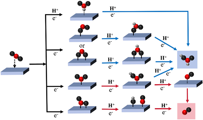
CO as the reduction product: Based on the current summary of possible reaction paths for the conversion of CO2 into CO, the following process can be summarized. Firstly, CO2 is dissolved in the electrolyte and then contacts with the catalyst to yield *CO2− intermediate through electron transfer to the adsorbed *CO2. The C atom in *CO2− is first combined with the electrode surface through the proton-coupled electron-transfer (PCET) process. Alternatively, the C atom and O atom in *CO2− can be parallel to the electrode surface. In this case, the *COOH intermediate is yielded by the combination of protons. Subsequently, the *CO intermediate is generated and desorbed from the catalyst surface as CO [74-76].
HCOOH as the reduction product: Unlike the CO pathway, the intermediates for the generation of HCOOH are not the same. The proposed pathways based on previous studies can be summarized as the following three pathways. The first is the formation of *CO2− followed by the PCET process, in which one or two O atoms in *CO2− combine with the electrode surface to yield *OCHO, followed by the acquisition of protons to yield HCOOH [77-80]. The second type is that the first proton in the aqueous solution is reduced to an H atom and adsorbed on the electrode. CO2 electrophilic attacks the H atom on the electrode to produce HCOO*, which is then transferred by protons to yield HCOOH [81]. The third pathway is similar to the CO generation pathway, in which a proton is obtained after the formation of *COOH to form HCOOH directly [82].
Since the pioneering work of Hori et al. in the 1980s and 1990s, tremendous efforts have been made in the research of electrocatalysts for CO2RR [83-85]. The CO2RR performance of the electrocatalysts was evaluated mainly from four aspects: current density, faraday efficiency (FE), stability, and energy efficiency (EE). Although electrocatalysts for CO2RR have shown increasingly excellent performance in recent years, they are often limited by high costs for practical industrial production of hydrocarbon products or carbon-oxygen products. At present, the research on this technology is still mainly limited to the laboratory scale, and there are still great difficulties in industrial production [86,87]. Therefore, there are still insurmountable obstacles in the avenues of electrocatalytic CO2 reduction to practical applications.
Large overpotential: CO2 possesses a very stable molecular structure with C=O bond energies as high as 805 kJ/mol, so a large amount of energy is required to activate the CO2 molecule, leading to a large overpotential for driving the reaction. The step of converting CO2 into the *CO2− intermediate requires a large potential of −1.49 V, which is the rate-determining step (RDS) of CO2RR [88,89]. In addition, *CO2− continues to form different reaction intermediates on the catalyst surface and desorbs via complicated proton coupling and electron transfer, which also requires a large overpotential to overcome the slow reaction kinetics [90]. Therefore, it is urgent to reduce the overpotential to improve the economy of the reaction.
Low selectivity: After CO2 is activated to form *CO2−, diverse products can be produced according to different electron transfers, including CO, formate, methane, ethylene, ethane, etc. [91]. The overpotential required to form the final product is usually greater than that required for CO2 reduction to *CO2−. Therefore, when CO2 occurs reduction, subsequent reduction reactions will occur spontaneously, making it difficult to terminate the reaction at specific steps to achieve high selectivity. More importantly, the potential of −1.49 V is much more negative than the potential of hydrogen evolution, the hydrogen evolution reaction (HER) will become a powerful competitive reaction to further reduce product selectivity [92].
Stability: The stability of electrocatalysts is an important indicator of catalyst performance. Furthermore, the stability of electrocatalysts determines their ability to maintain activity and selectivity under long-term constant current or constant potential [93]. Most of the CO2RR electrocatalysts reported in recent years were stable up to a few hundred hours before structural collapse and active site deactivation. However, the stability of catalysts for industrial applications requires at least thousands of hours, which is still far from the stability of electrocatalysts studied so far [86,94].
Energy efficiency (EE): The previous performance indicators of CO2RR mostly focused on current density, selectivity, and FE. However, as a guiding standard for the industrial implementation and economic feasibility of CO2RR, EE should also be fully considered [95]. EE is the percentage of the energy of target products divided by the total power input of the electrolysis system, closely related to battery voltage and FE [96,97]. From the perspective of technical and economic analysis, it is necessary to maximize the EE of the CO2RR system at commercially relevant current densities to reduce total power input as electricity accounts for a significant portion of production costs [98]. On the other hand, due to the thermodynamic and kinetic consumption of the oxygen evolution reaction (OER) process occurring in the anode, the anode reaction in the CO2RR system consumes a significant part of the supplied electrical power [99,100].
Low CO2 utilization: Due to the fact that HER is more advantageous in kinetics than CO2RR under acidic conditions, most current research on CO2RR favors alkaline conditions [101,102]. However, most of the input CO2 reacts with OH− in the electrolyte to produce CO32− due to strong local alkaline conditions. The formation of carbonates poses significant limitations on carbon utilization efficiency [103]. Specifically, for each pair of electrons transferred in the CO2RR process, the cathode produces a hydroxide that reacts with half of the CO2 to generate a carbonate. Therefore, the maximum carbon utilization is 50% for two electron transfer processes such as CO2 to CO. Carbon utilization is lower for multiple electron transfer processes [104]. The inefficient utilization of CO2 in CO2RR severely limits its prospects.
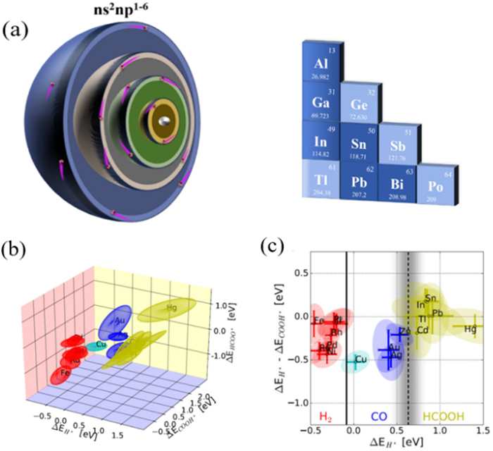
The CO2RR product is dependent on the reaction intermediate, which is related to the active site of the catalyst. As a group of metal resources with abundant reserves, p-block metals are cheaper than precious metals or other metals that produce formic acid, resulting in significant economic advantages as electrocatalysts for CO2RR. In addition, p-block metals exhibit high electronegativity and low ionization energy due to their unique electronic structure (ns2np1 to ns2np6) (Fig. 2). The p-block metals have a wide range of variable valence states, giving them the ability to form p-block metal-based catalysts with different valence states [68]. More importantly, due to their characteristic oxyphilic, the p-block metals facilitate the adsorption and formation of oxygen-bonded intermediates, such as *OOCH and *OCHO, which are major intermediates for the production of formate [105,106]. In addition, the low adsorption of the p-block metal for *H allows them to inhibit HER. Based on the above reasons, p-block metal-based MOFs are effective in reducing CO2 to formate or CO. Rossmeisl and co-workers [107] compared the groups in terms of multiple binding energies of intermediates calculated by density functional theory. The results showed that the p-block metals have a unique selectivity for HCOOH (Figs. 2b and c).
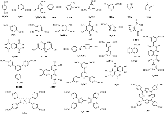
Due to the controllable structure and abundant active sites, various pristine MOF materials have been developed as effective catalysts for CO2RR [108]. MOF catalysts are conducive to exposing active sites and enriching reaction substrates during CO2RR due to their unique porous structure. More importantly, the well-defined crystal structure provides a promising opportunity for mechanistic investigations. Here we summarize and discuss the progress of p-block metal-based MOFs in the CO2RR. The ligands involved in MOFs and MOF-derived catalysts mentioned in this review are shown in Fig. 3.
Among numerous catalysts, In-based catalysts exhibit outstanding performance in converting CO2 into formate. They are considered ideal catalysts due to their abundant reserves and environmental friendliness [109-111]. However, many In-based catalysts, including In oxide [112], In sulfide [113], and In complexes [114] hinder their further application due to their low atomic utilization and poor stability. Encouragingly, metal-organic frameworks (MOFs) with adjustable structures, tailorable channels, and highly dispersed active sites are considered potential electrocatalytic materials [115].
In 2020, Gu's group [116] used an In-based MOF named In-BDC for the electro-reduction of CO2 to formate, which can catalyze with a FEHCOO− exceeded 80% within the potential window of −0.419 V to −0.769 V (Fig. 4a). The maximum FEHCOO− of In-BDC was 88% with a maximum turnover frequency (TOF) of 4798 h−1. Moreover, In-BDC maintained stable FE and current density within 21 h, indicating its stability in CO2RR. Compared with commercial In catalysts, In-BDC presented better catalytic performance, indicating the promising application of In-MOFs in CO2RR.
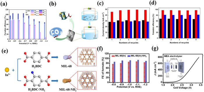
In order to further improve the catalytic activity of In-MOF catalysts, strategies including defect engineering [117], post-functionalization modification [118], and metal doping [119] have been attempted. In 2020, Martin, Yang, and Han et al. [120] developed an ionic liquid electrolyte-assisted electrodeposition method to realize the direct growth of MOFs on substrates (Fig. 4b). Compared with the MFM-300(In)-t prepared by thermo-synthesis, electro-synthesized MFM-300(In)-e possesses more defects due to the competitive coordination of OAc− in high concentrations of EmimOAc electrolytes, which was supported by BET, FTIR, and XPS. In addition, although the samples had the same crystal structure, the conductivity of the obtained MFM-300(In)-e was improved by one order of magnitude due to the closer contact between MOF and substrate. As a result, MFM-300(In)-e exhibited a FEHCOOH of 99.1% with a jHCOOH of −46.1 mA/cm2, which exceeded all other MOFs at that time. According to DFT calculations, the formation of the *COOH on MFM-300(In)-e was spontaneously compared with that on MFM-300(In)-t, indicating that the absorption of the *COOH intermediate is facilitated by the defective In(Ⅲ) sites present in MFM-300(In)-e (Figs. 4c and d). It was also found that the *COOH intermediate is easier to form than *CO, resulting in a high selectivity for formate. This work pioneers an efficient method for the electrosynthesis of MOF catalysts while demonstrating the great potential of defect engineering for CO2RR.
Regulating the performance of MOF catalysts through the functionalization of ligands has also proven to be a promising strategy for constructing excellent catalysts. In 2021, Xia et al. [121] reported an In-MOF (MIL-68(In)-NH2) with amino groups for the reduction of CO2 into formate. The author introduced amino groups based on the existing ligands, which serve as free radicals to participate in the framework construction, rather than coordinating with In sites (Fig. 4e). Specifically, the strong electron donating ability of amino groups can significantly increase the electron density of In atoms. The change in electron density around the In atom is beneficial for the activation of CO2 and the binding of reaction intermediates, thus improving the catalytic performance effectively [122]. As a result, MIL-68(In)-NH2 had a higher current density and FE. FEHCOO− of MIL-68(In)-NH2 reached the maximum value of 94.4% at −1.1 V and remained stable within 24 h (Figs. 4f and g). The author suggested that amino groups can enrich CO2 adsorption via acid-base interactions and stabilize *CO2− intermediates via hydrogen bonds [123,124]. It is worth noting that MIL-68(In)-NH2 inevitably undergoes during the electrocatalytic process, but the retained presence of amino groups still leads to a high FE of formate. This work reveals the influence of amino functionalization on active sites and proposes potential strategies for modifying MOF electrocatalysts with functional groups on ligands.
In addition to immobilized amino groups, modification of the enzyme-mimicking redox-active units can also be effective in improving catalytic activity. Ding et al. [125] reported an In-MOF ((Me2NH2+)[InⅢ-(TA)]·3DMF·1.5H2O) based on a redox-active tetrathiafulvalene (TTF) ligand H4TA, which is an inorganic analog with a metal site (Ni) replacing the central C=C bond (Fig. 5a). Compared to manufacturing structural defects that expose more catalytic sites, these unsaturated metal active sites are not dependent on the generation of structural defects. The unsaturated Ni sites in the ligand can emulate the activity of formate dehydrogenase and CO dehydrogenase [NiS4] sites, thereby effectively converting CO2 into formic acid in CO2RR. Compared with isomorphic (Me2NH2+)[InⅢ(TTFTB)]·0.7C2H5OH·DMF, (Me2NH2+)[InⅢ(TA)]·3DMF·1.5H2O exhibited significantly enhanced the catalytic performance in CO2RR. At the applied potential of −1.3 V, the FEHCOOH of (Me2NH2+)[InⅢ(TA)]·3DMF·1.5H2O reached 89.6% with a jHCOO− of −36.0 mA/cm2 (Fig. 5b). There was no significant decrease in FE and current density over 12 h, demonstrating the good stability of the catalyst. Adsorption isotherms confirmed that [NiS4] can serve as a binding site for CO2. The author proposed that unsaturated redox activity [NiS4] can serve as both CO2 binding and catalytic sites, simulating the active [NiS4] centers in formate dehydrogenase and CO dehydrogenase. DFT calculations suggested that the free energy of (Me2NH2+)[InⅢ(TA)]·3DMF·1.5H2O is lower than that of (Me2NH2+)[InⅢ(TTFTB)]·0.7C2H5OH·DMF, confirming that the [NiS4] sites indeed make an important role in the catalytic process (Figs. 5c and d).
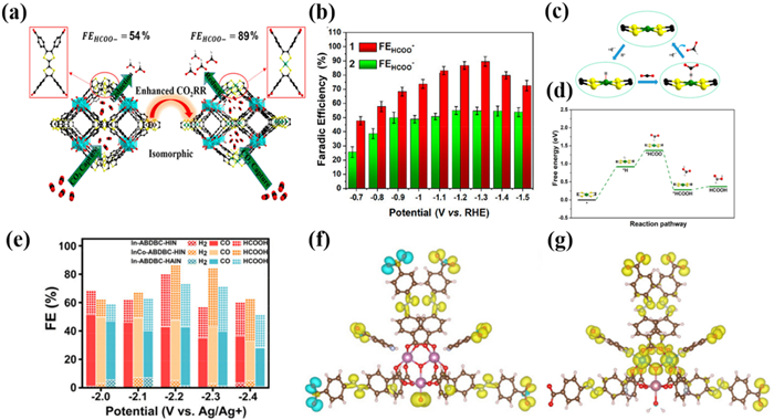
In addition to regulating ligands, adjusting metal centers can also have a positive effect on CO2RR. The addition of secondary metals to construct bimetallic compounds has been supposed to be an effective strategy for improving activity. In 2023, Zhai et al. [119] reported a series of In-based trinuclear MOFs (In-ABDBC—HIN, In-ABDBC—HAIN, and InCo-ABDBC—HIN) and investigated the effect of ligand functional groups in CO2RR. The presence of Co and functional groups significantly increased the specific surface area and CO2 adsorption capacity of the materials as revealed by N2 and CO2 adsorption-desorption isotherms. As a result, InCo-ABDBDC—HIN had the highest current density, followed by In-ABDBC—HIN and In-ABDBC—HAIN. The experimental results suggested that the substitution of Co atoms for In atoms is beneficial for improving catalytic performance, while the introduction of amino groups in the ligand decreased the catalytic performance. So InCo-ABDBC—HIN exhibited a maximum current density of −21.2 mA/cm2 and a maximum FE of 81.5% for the C1 product at −2.2 V (Fig. 5e). According to DFT calculations, unpaired electron distributions were not observed on the metal atoms in In-ABDBC—HIN and In-ABDBC—HAIN, indicating that amino modification hardly affects the electron density in the In atoms. After doping Co into an In cluster, InCo-ABDC—HIN exhibited significant unpaired electron distribution on the Co atom. Amino group modifications both increase steric hindrance to prevent CO2 adsorption at the active sites and lead to extremely poor DOS intensity to reduce conductivity, which ultimately negatively affects the catalytic performance (Figs. 5f and g).
As the research continues, the poor conductivity of most In-MOF materials hinders the further improvement of the catalytic performance. How to enhance the conductivity becomes a crucial issue. Zhao's group [126] proposed an in situ pyrolytic construction of carbon nanoparticle-modified In-MOF materials by introducing a small-molecule carbon source to improve the catalytic properties of the materials (Fig. 6a). A three-dimensional In-MOFs {(Me2NH2)[In(BCP)]·2DMF}n (V11) with two types of channels was first constructed as a model based on the H4BCP ligand. Nanoscale pores and good stability facilitate the introduction of carbon sources. Considering the molecular size with respect to the carbonization temperature, methylene blue was screened as a carbon source to be introduced into the framework. After carbonization, methylene blue was converted into uniformly sized carbon nanoparticles while causing V11 to produce a large number of mesopores. As a result, the modified catalysts exhibited a significant enhancement in selectivity and current density, which was attributed to faster charge transfer with fully exposed metal active sites (Fig. 6b). More importantly, this strategy was also applicable to classic In-MOFs materials such as MIL-68, PF-110, and CPM-5 (Figs. 6c and d).
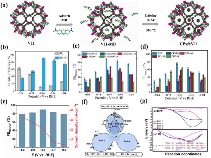
Hu et al. [82] instead chose conductive MOFs with the ability to provide electrons as catalysts. They prepared a classic conductive large π conjugated In-based MOF (In-TCPP) nanosheets with different sizes for CO2RR. In the flow cell under alkaline conditions, FEHCOO− of In-TCPP nanosheets reached the maximum FE of 90% at −0.8 V, and the CEE was 63.8% (Fig. 6e). It is worth noting that the selectivity and current density of In-TCPP remained almost unchanged within 50 h, indicating its excellent stability. In addition, in situ ATR-FTIR and DFT calculations confirmed that the In sites as the active sites could stabilize the *COOH intermediates, which facilitates the formation of formate (Figs. 6f and g). This work encourages further exploration of the potential of conductive MOF materials for CO2RR applications.
Bi-based materials have been shown to be effective electrocatalysts for the electrochemical conversion of CO2 into HCOOH [127]. Bi-based catalysts have received widespread attention due to the following advantages: (1) Low toxicity and environmental friendliness [128]; (2) Effective inhibition of the competitive reaction HER [129,130]; (3) High selectivity due to strong affinity for *OCHO intermediates and weak adsorption capacity for *CO intermediates [131]; (4) Lower cost and better stability compared to precious metal catalysts. Recently, Bi-MOFs have become potential Bi-based catalysts due to their clear coordination environment, exposed active sites, and controllable structure.
In 2020, Sun et al. [132] prepared a highly stable 2D Bi-based MOF (Bi-MOF) with permanently accessible porosity for CO2RR. Bi-MOF was constructed from helical BiO rods and H2BTC ligands to form a 2D open framework, leading to a FE of 92.2% at −0.9 V within 30 h (Fig. 7a). The authors concluded that the larger pores and highly exposed two-dimensional structure of the framework facilitated mass transfer during the reaction. The abundant micropores are favorable for CO2 enrichment and increase the local substrate concentration. More importantly, the open framework enables the Bi sites to be fully exposed, resulting in a mass-specific partial current density much higher than those of commercial Bi2O3 and Bi nanosheets. X-ray absorption fine structure spectroscopy (XAFS) showed that BiⅢ sites in the channels can be stabilized during the reaction, which plays an important role in enhancing CO2 adsorption and HCOOH production.
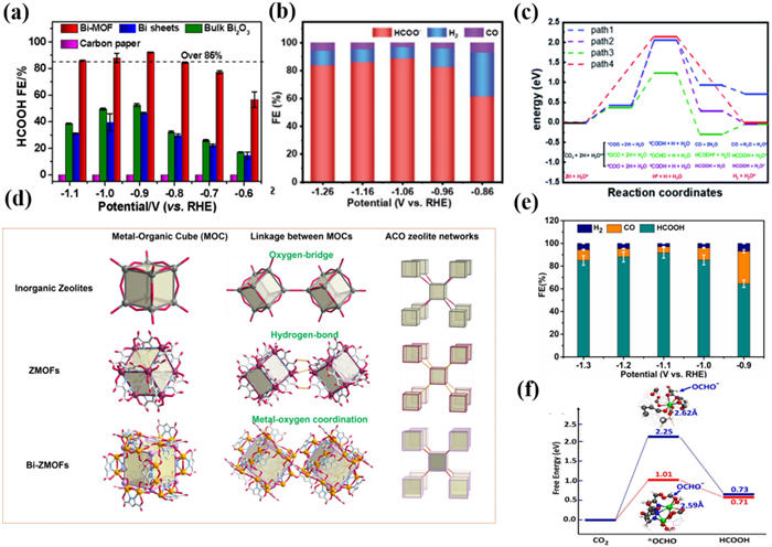
Zhang et al. [128] constructed a highly stable Bi-based MOF Bi2O(H2O)2(C14H2O8)·nH2O·nH2O (SU-101) with nanorod morphology based on H4EA ligand. Impressively, SU-101 could maintain a stable crystal structure in a wide pH range of 2–14. SU-101 exhibited a maximum FEHCOO− of 93.66% at −1.06 V with jHCOO− of −14.57 mA/cm2 (Fig. 7b). PXRD patterns suggested that SU-101 still maintained its original crystalline structure with rod-shaped after the electrocatalytic process. DFT calculations compared four possible reaction pathways, indicating that *OCHO is a critical reaction intermediate (Fig. 7c). The author believed the adsorption strength of Bi(Ⅲ) in SU-101 is moderate, not weak enough for HER to occur, and at the same time weakens the adsorption of C=O bonds to inhibit the generation of CO.
In 2023, Zhou and Li et al. [133] constructed two Bi-MOFs (PZH-1 and PZH-2) to explore the effect of the interaction between metal centers and the coordinating environment on CO2RR. One of them has a Bi-N coordination structure and the other has all Bi coordinated to oxygen atoms. The author was inspired by zeolitic metal-organic frameworks (ZMOFs) and successfully synthesized a 3D PZH-1 with an unreported zeolitic ACO topological structure by using a ligand-directing strategy. Compared with the hydrogen-bonded ZMOFs, Bi-ZMOF constructed by metal-oxygen coordination bond can improve the stability of the zeolite frameworks. And the [Bi2(H2O)N4O8] binuclear units were observed for the first time in Bi-MOFs. Interestingly, each [Bi2(H2O)N4O8] unit can bridge 8 identical [Bi2(H2O)N4O8] units, to form an interesting Bi24 cubic cage with a pore size of approximately 12 × 12 Å2, which is the first Bi cube cage in MOFs (Fig. 7d). The FEHCOOH for PZH-1was up to 91% at −1.1 V (Fig. 7e). After 12 h of electro-reduction reaction, XPS suggested that the main oxidation state after the reaction is Bi(Ⅲ), and no other Bi species were produced, confirmed the PZH-1 has good stability. In addition, the author prepared PZH-2 based on the H4PMA ligand with a two-dimensional layered structure for comparison. The results indicated that the CO2RR performance of PZH-2 was worse than PZH-1, confirming that Bi-N coordination promoted the conversion of CO2 to HCOOH. DFT calculations indicated that porous structures are beneficial for exposing the active sites and further absorption of CO2, while the Bi-N coordination facilitates the transfer of electrons from ligands to active sites, thereby activating the absorbed CO2 and stabilizing intermediates (Fig. 7f).
Although Bi-based MOF electrocatalysts have exciting performance in CO2RR, low conductivity likewise hinders their further application. Conductive Bi-based MOFs attract the attention of researchers. Hu's group [134] reported a conductive Bi-MOF (Bi-HTPP) with unsaturated Bi(Ⅲ) active sites and rare zigzagging corrugated topology (Fig. 8a). Bi-HTPP possessed an excellent conductivity of 1.65 S/m above that of most Bi-MOFs. Electron paramagnetic resonance (EPR) spectroscopy revealed the presence of unpaired electrons, confirming the presence of unsaturated Bi(Ⅲ) sites. The Bi-HHTP exhibited a maximum FEHCOOH of 95% at −0.7 V with 68.8% CEE (Fig. 8b). It is worth noting that there was no significant performance decay after 30 h of electro-reduction reaction, which is attributed to the far more stable structure than other reported Bi-MOFs confirmed by in situ Raman spectra. DFT calculations indicated that the high selectivity of Bi-HTPP for HCOOH is due to the strong *COOH intermediate at the Bi(Ⅲ) site, which weakens the C=O bond (Fig. 8c).
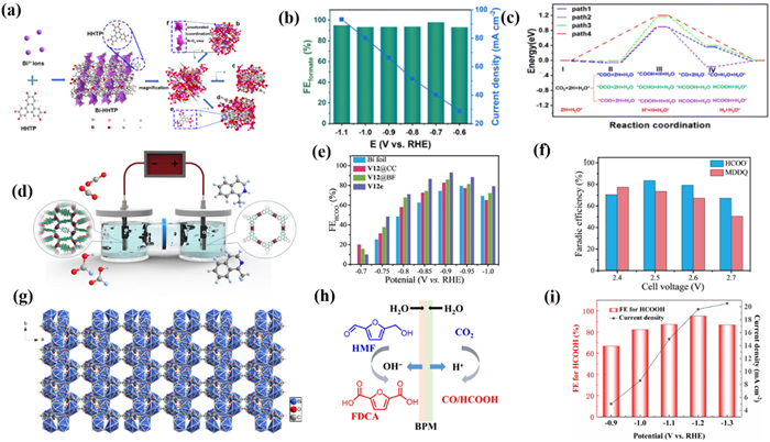
Zhao's group [135] constructed a novel Bi-MOF {(Me2NH2)[Bi(BDP)]·4DMF·2H2O}n (V12) based on a naphthalenediimide-based ligand with redox properties, which had nanoscale one-dimensional pores and a total free volume of up to 69.8%. The author further prepared V12e using the classical ionic liquid-assisted electrochemical deposition method, which created more ligand-missing defects while obtaining a unique flower-like structure. The presence of defects effectively enhances the activity of Bi sites, and the unique nanostructure promotes the exposure of active sites (Fig. 8d). As a result, V12e prepared by electrodeposition had a higher FEHCOO− of 93.2% and 2-fold current density enhancement compared to V12 (Fig. 8e). In addition, in order to further reduce energy consumption and obtain a variety of high value-added products, the author utilized the oxidation reaction of tetrahydroisoquinoline instead of OER to form a new system. This strategy not only promoted sluggish kinetics but also realized the simultaneous generation of high value-added dihydroisoquinolines and formate, which provides inspiration for the construction of an efficient electrolytic system (Fig. 8f). He et al. [136] constructed a Bi-MOF based on 2,5-furandicarboxylic acid to catalyze the CO2 reduction reaction paired with 5-hydroxymethylfurfural oxidation (Fig. 8g). Interestingly, the 5-hydroxymethylfurfural generated by 5-hydroxymethylfurfural oxidation will serve as a self-generated ligand to construct MOF materials for CO2RR (Fig. 8h). The FEHCOO− of constructed Bi-MOFs exceeds 95% at −1.2 V with −19.6 mA/cm2. Accompanied by the catalyze of Ni(OH)2/CP prepared by electrodeposition in anodic, the new electrolysis system realized the production of FEHCOOH with 95.6% and FEFDCA with 75% (Fig. 8i).
Unlike In-MOFs, many studies revealed that Bi-MOFs undergo structural evolution during the CO2RR process, typically manifested as structural destruction with Bi(Ⅲ) being reduced to Bi(0) particles [137,138]. Lock et al. [139] reported a Bi(btb) with face-sharing BiO9 chains as a precatalyst for CO2RR. The authors have carried out an in-depth study of the structural evolution of Bi(btb). Grazing-incidence X-ray diffraction indicated that the pristine crystalline state of Bi(btb) disappears after 15 min of immersion in a KHCO3 electrolyte solution to produce crystalline Bi under CO2RR conditions. Pair distribution function analysis suggested that the carbonate and bicarbonate anions partly replace the linkers. As a result, the crystalline Bi(btb) was transformed into highly dispersed Bi nanoparticles embedded in a carbon matrix, which can produce formate with a FE of up to 95% (Figs. 9a and b).
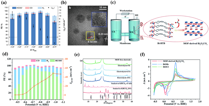
Similarly, Gu and his co-workers [140] prepared two examples of Bi-based MOFs for CO2RR, namely Bi-BTB and Bi-TATB, and proposed that Bi-based MOFs can be converted into carbonates in the presence of subcarbonate (Bi2O2CO3), proving the significance of the HCO3− salt effect (Fig. 9c). The FEHCOO− of Bi-BTB reached 96.1% with a jHCOO− of −12.7 mA/cm2 at −0.669 V (Fig. 9d). In addition, after the continuous electrolysis process at −0.669 V for 48 h, the electrocatalyst exhibited excellent electro-reduction stability. Through the PXRD patterns, it was found that Bi-BTB underwent structural changes induced by HCO3− during CO2RR. Bi2O2CO3 was the dominant phase with good stability in the CO2RR process (Fig. 9e). The author believed that based on the Hard Soft Acid Base theory, Bi-BTB is theoretically unstable due to Bi(Ⅲ) ions and carboxylates belong to intermediate acids and hard bases, respectively. Therefore, the Bi-O bond of Bi-BTB may be disrupted by HCO3− in the electrolyte, achieving in situ conversion to Bi2O2CO3 (MOF-derived Bi2O2CO3). When NaSO4 was used as the electrolyte instead of KHCO3, the corresponding transformation did not take place but was reduced to Bi nanoparticles under the action of the potential, further demonstrating the induced effect of HCO3−. From these results, it can be concluded that the Bi-O bond of Bi-MOF could be destroyed by HCO3−. Furthermore, Bi2O2CO3 derived from MOF has a layered structure composed of [Bi2O2]2+ and CO32−, which is analogous to layered Bi oxide halides. Compared with BiOCl and BiOBr, MOF-derived Bi2O2CO3 had better stability and selectivity, which is more resistant to reduction to metal Bi(0) during the CO2RR process (Fig. 9f).
Qiao et al. [138] used CAU-17 as a model to further monitor the transformation process based on in situ characterization techniques. In the KHCO3 solution, the nanorod-like CAU-17 transformed into a nanosheet-like Bi2O2CO3 (Fig. 10a). Through in situ Raman spectra, it was visualized that the bands at 820 and 1002 cm−1 attributed to C—H in the BTC3− gradually weakened, while a new band assigned to the stretching vibration of C—O in Bi2O2CO3 appeared at 1069 cm−1. This result confirmed that the Bi coordination environment is altered and that the process is electrolyte concentration dependent. Subsequently, in situ Raman spectra further confirmed that with a gradual increase in overpotential, Bi2O2CO3 in turn transformed into Bi nanosheets with the abundant unsaturated site, resulting in a high FEHCOO− of 92% (Fig. 10b). This work details that the reconstruction of CAU-17 consists of two steps: electrolyte-mediated and potential-mediated.
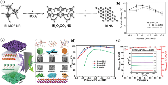
Likewise, Zhu and Xu et al. [141] explored the structural evolution of Bi-MOFs constructed with different ligands including H3BTC, H2BDC, and H2IDC during CO2RR. Although Bi-BTC, Bi-BDC, and Bi-IDC have different morphologies such as cubic, rod, and flower clusters, all of them were converted to ultrathin Bi-nanosheets during the CO2RR process (Fig. 10c). At a potential of −1.178 V, Bi-ene provides a FEHCOO− of 95% as well as a jHCOO− of −70 mA/cm2, which far outperforms commercial Bi powders (Fig. 10d). Subsequently, by pairing the reaction with methanol oxidation, the authors further achieved the simultaneous generation of formate at both the cathode and anode with close to 100% selectivity (Fig. 10e).
Liang et al. [142] prepared a Bi-based MOF (Bi-MOF) with BiO9 nodes for CO2RR, which could be transferred into a mixture of Bi and Bi2O2.5 in CO2RR (Fig. 11a). For Bi-MOF, the FEHCOOH of 92% and jHCOO− of −150 mA/cm2 were achieved at −0.64 V, which could be maintained for 30 h (Fig. 11b). The Bi-MOFs transformed into Bi/Bi2O2.5 with perpendicular sheet morphology during the reaction. The Bi/BiO interface is beneficial for reducing the free energy of formation by the *OCHO intermediate [130], leading to high HCOOH selectivity (Fig. 11c).
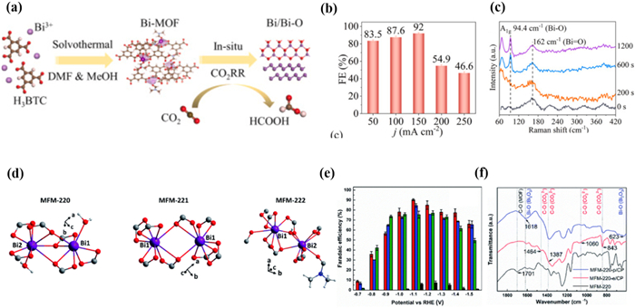
Although the reconstruction process of Bi-MOFs has been well elucidated, the effect of the initial structure of Bi-MOFs on the reconstructed products has rarely been investigated. Therefore, Floriana Tuna et al. [143] reported a series of Bi-based MOFs (MFM-220, MFM-221, and MFM-222) based on the H4BPTC ligand with different porosity to explore the effect of porosity in the structural evolution of MOFs during the CO2RR process (Fig. 11d). Bi-MOFs were named MFM-200/−221/−222-e and 200/−221/−222-p when reacting with electrolytes and applying external potentials, respectively. Among them, MFM-220-p originates from the highest porosity MFM-220 had the best catalytic performance for CO2RR. The FE of HCOOH was 90.4% at −1.1 V (Fig. 11e). In addition, MFM-220-p maintained activity against CO2RR for at least 5 h. After adding the electrolyte for 30 min, PXRD patterns and FT-IR spectra confirmed the presence of Bi2O2CO3 in MFM-220-e, MFM-221-e, and MFM-222-e (Fig. 11f). And MFM-220-e undergone the fastest transformation, while MFM-222-e undergoes an incomplete transformation. After applying an external potential, α-Bi2O3 and Bi appeared in MFM-220-p, MFM-221-p, and MFM-222-p. Similarly, MFM-220-p has the fastest conversion process, while the conversion of MFM-222-p was the slowest. The fast and complete conversion of porous MFM-220 improves the conductivity of MFM-220-p/CP, thereby enhancing the catalytic activity for CO2RR. Therefore, the effect of porosity on the reconfiguration catalysts of Bi-MOFs should not be neglected, and high porosity contributes to the rapid reconfiguration into a highly porous structure, which improves the catalytic activity.
Sn-based materials can still be used as the potential catalysts for the electrocatalyst for CO2 to formate because of their low cost and non-toxic [144-146]. Including Sn alloys [45], Sn nanoparticles [147], Sn oxides [148], and nonmetal doped Sn compounds [149] have been reported successively. For Sn-based MOFs, due to their clear Sn metal active sites and porous structure, they are expected to become potential electrocatalysts for achieving CO2RR.
In 2022, Zhang et al. [150] synthesized a Sn-MOF using a more environmentally friendly atmospheric stirring method in an aqueous solution, and further prepared Pb infiltrated Sn-MOF catalysts (Fig. 12a). It is worth noting that the presence of Pb in the form of Pb(0) or PbO rather than coordination with ligands, therefore the basic structure of Sn-MOF did not change substantially. Sn-MOF exhibited the FEHCOO− as high as 91.8% at −1.2 V. However, Sn-MOFPb5 exhibited a higher FEHCOO− compared with pure Sn-MOF, with FEHCOO− reaching 94.6% at −1.1 V (Fig. 12b). DFT calculations indicated that Sn centers have strong interactions with*OCHO intermediates, which is a common reaction pathway intermediate for generating HCOOH, resulting in high formate selectivity for Sn-MOF (Fig. 12c).
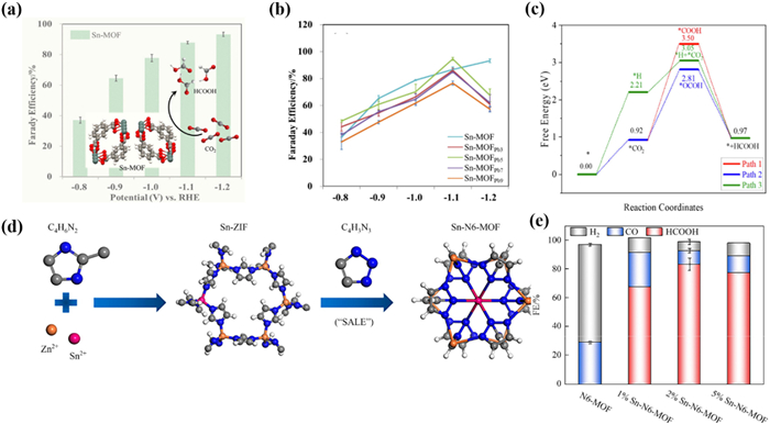
In the same year, Li et al. [151] synthesized a series of six N-coordinated Sn-MOFs (Sn-N6-MOFs) through solvent assisted linker exchange (SALE) strategy (Fig. 12d). Firstly ZIF-8 was used as a template to construct Sn-ZIF through metal doping. Subsequently, HTA was introduced to form Sn-N6-MOFs with Sn six-coordinated configuration via the SALE process. In the CO2RR processes, the synthesized 2% Sn-N6-MOF exhibited high FEHCOO− with 85% at −1.23 V (Fig. 12e). Moreover, Sn-N6-MOF maintained a FEHCOO− of over 80% within 6 h, but the increase in current density within the first hour indicated that the Sn-N6-MOF may be restructured during the CO2RR. The in situ Raman measurement indicated that the catalyst undergoes in situ dynamic recombination during the electro-reduction CO2RR process, leading to a phase transition from 2% Sn-N6-MOF to Sn nanoclusters. Specifically, due to the destruction of organic ligands in the Sn-N6-MOF framework, the original framework structure of the catalyst was destroyed and reconstructed. The reconstruction of Sn-N6-MOF generated Sn nanoclusters as active sites for CO2RR during the electro-reduction CO2RR process.
Due to the controllable structure of MOF materials, the functionalization of Sn-based MOFs can also effectively improve the activity of CO2RR. In 2022, Sun et al. [152] synthesized a series of controllable functionalized Sn-CPs. The author achieved the amino functionalization of Sn-CPs by introducing one or two amino groups into the ligand PTA, named Sn-PTA, Sn-aPTA, and Sn-DaPTA, respectively (Fig. 13a). The FEHCOOH of Sn-DaPTA up to 85% with a jHCOOH of −11 mA/cm2 at −0.8 V (Fig. 13b). Moreover, Sn-DaPTA exhibited high stability during the 18 reuse cycles (Fig. 13c). Compared with Sn-PTA, the introduction of -NH2 effectively enhanced the CO2 adsorption capacity of Sn-aPTA and Sn-DaPTA, resulting in a higher concentration of CO2 around the electrode surface. This can effectively improve the activity of CO2RR and inhibit the precipitation of hydrogen. Moreover, by exploring the electron transfer process of Sn-CPs in the CO2RR process, it was found that the -NH2 on the Sn-CPs can effectively enrich CO2, promoting the transfer of the electron to form *CO2−. In addition, the coordinated environment of Sn was changed by amino groups, leading to more Sn(Ⅱ) active sites on the surface for CO2RR, facilitating the conversion of CO2 to formate.
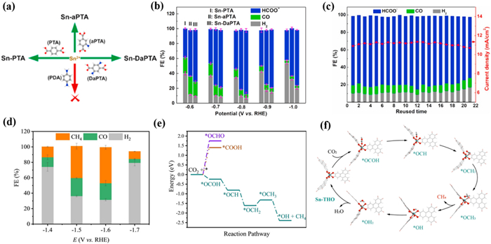
The selectivity of MOF catalyst is not only related to the type of metal element but also to the coordination environment, such as the coordination structure and its microenvironment [149]. Most studies have shown that Sn-based MOFs have excellent selectivity for the electrochemical conversion of CO2 into formate. However, Chen's group [153] found a Sn-based MOF (Sn-THO) has excellent performance for the conversion of CO2 into CH4, which is the first example of a Sn-based MOF with high selectivity for hydrocarbon. It is worth noting that Sn-THO was easily activated in 1 mol/L KOH aqueous solution and remained stable at room temperature during 24 h. The oxidation state, structure, and morphology of Sn-THO were still maintained without generating any Sn or SnOx clusters after undergoing CO2RR. The authors believed that Sn-THO maintains high stability due to its interpenetrating structure and rigid ligand. Importantly, compared with other Sn-based catalysts, Sn-THO exhibited special FECH4 of 46.5% with a jCH4 of −34.5 mA/cm2 at −1.6 V (Fig. 13d). DFT calculations indicated that SnⅣ sites of Sn-THO are isolated, resulting in the inability to form V-shaped *OCHO intermediates at neighbouring metal sites via bridging modes. The special coordination geometry and environment of SnⅣ ions in Sn-THO are conducive to the generation of CH4 by key *OCOH species, which can greatly inhibit the generation of HCOOH and CO by *OCHO and *COOH species, respectively, leading to high FECH4 (Figs. 13e and f). This work highlights the coordination environment of the active site in the catalytic selectivity for CO2RR.
Enhancing the electrocatalytic performance of MOFs through the synergistic effect of bimetallic materials is also a promising strategy. In 2023, Wu et al. [154] synthesized a series of Sn-In bimetallic MOFs (Sn-MOF/Inx) by PTA. By adjusting the amount of In added, the composition and structure of the MOF could be adjusted to prove the catalytic activity. PXRD patterns confirmed the successful introduction of the In metal and the incorporation of In had no effect on the structure of Sn-MOF. Sn-MOF/In6 had a rougher surface, evenly dispersed particles, and a loose structure, resulting in less susceptibility to agglomeration. Among all the Sn-MOF/Inx, Sn-MOF/In6 had the highest selectivity for formate with a selectivity of about 97.5% at −0.96 V, which was higher than that of 85% for Sn-MOF (Fig. 14a). The results displayed that the incorporation of In can improve the specific surface area of Sn-MOF/In6 to promote gas adsorption, and significantly enhances the contact between the active site and CO2, thereby improving the selectivity of formate.
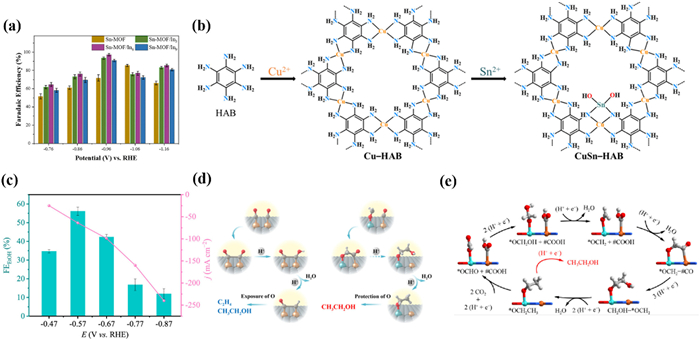
Similarly, Chen and Liao et al. [155] designed a new MOF (CuSn-HAB) based on HAB. Due to the special -NH2 sites of the HAB, Cu-HAB still has protons that can be removed. Taking advantage of this characteristic, the author designed an unprecedented heterogeneous metal Sn-Cu double sites, i.e., a pair of SnN2O2 and CuN4 sites bridged through μ-N atoms (Fig. 14b). Surprisingly, the CuSn-HAB exhibited a high FEethanol of 56% with a jethanol of −68 mA/cm2 at −0.57 V (Fig. 14c). Compared with Cu-HAB, CuSn-HAB avoids the production of ethylene and has specific selectivity for ethanol. Mechanistic studies have shown that the Sn sites have a stronger affinity for oxygen atoms compared to Cu. This enhanced oxygen atom affinity can effectively promote the formation of the crucial intermediate *OCH2 rather than *CO at the Cu sites. *OCH2 provided better protection of the C—O bonds, thus preparing for ethanol production. Specifically, compared with the common Cu-Cu sites, the Cu-Sn sites were more conducive to the asymmetric C—C coupling reaction between *CO and *OCH2 to form the *CO-*OCH2, which is conducive to the generation of ethanol products (Figs. 14d and e).
Compared to the MOF materials constructed based on In, Bi, and Sn, relatively few other p-block metal-based MOF materials have been reported. There is currently limited research on other metal-based MOFs in the p-block. This section mainly introduces the application of Al-based and Pb-based MOFs in CO2RR.
In 2015, Yang and Yaghi et al. [156] prepared an Al2(OH)2TCPP-Co MOFs thin film based on porphyrin ligands with nanoscale by selecting MOFs with catalytic connection units (Fig. 15a). Specifically, 50 times Atomic Layer Deposition (ALD) cycles were performed on the Al film deposited on a conductive carbon electrode and the Al film was transformed into a porphyrin containing [Al2(OH)2TCPP-M] (M=Zn, Cu, and Co). Electrochemical testing showed that the selectivity of Al2(OH)2TCPP-Co for CO exceeded 76% with a high TON of 1400 in 7 h (Fig. 15b). Importantly, most of the active sites in Al2(OH)2TCPP-Co were reduced to Co(Ⅰ) during the catalytic process. This research suggests the potential of ALD technology in the precise synthesis of MOF catalysts.
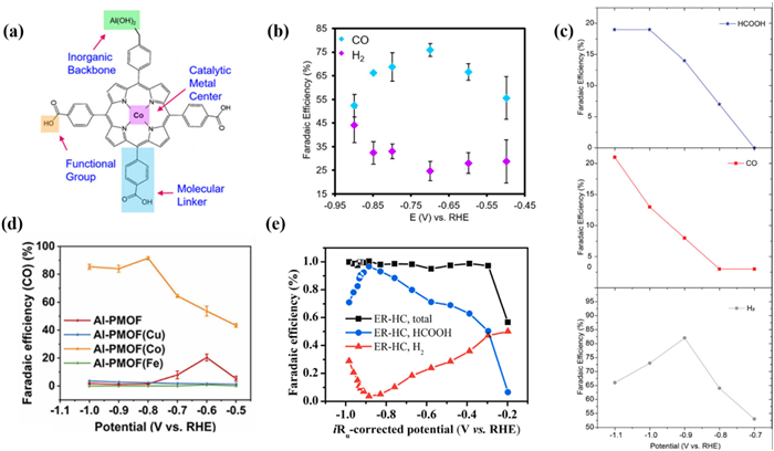
In 2020, F. M. Toma et al. [157] prepared an example of Al-MOF (MIL-53(Al)) for CO2RR. Compared with Al foil, the total FE of CO and formate was as high as 40% at −1.1 V (Fig. 15c). It is worth noting that Al(Ⅲ) in MIL-53(Al) underwent a reduction in CO2RR to form Al(0) active sites. However, the spatial confinement originating from MIL-53(Al) can stabilize the catalytic sites. The author suggested that limiting the Al centers within the MIL-53(Al) framework can inhibit HER activity and significantly enhance the electro of CO2. By changing the microenvironment around the metal active sites and providing a confined space similar to the enzyme chamber, unique catalytic performance can be endowed. Light irradiation may affect the electronic properties of certain electrocatalysts, such as accelerating electron transfer and reducing the binding energy between molecular catalysts and CO2 [158]. Therefore, photocoupled electrocatalytic CO2 reduction is an emerging method to improve the EE of electrocatalytic CO2 reduction [159]. In 2023, Li et al. [160] proposed for the first time a photo-coupled electrocatalyst with Al-O chains as metal nodes and transition metal sites as metal centers. The ability of Al-PMOF(Co) to electro-reduce CO2 to CO was satisfactory with a FECO of ~90% in 35 h (Fig. 15d). The results indicated that incorporating Co into Al-PMOF can activate the CO2 and subsequent electro-reduction. DFT calculations suggested that the introduction of Co in Al-PMOF regulates the electronic properties of the d state and optimizes the adsorption of CO2, intermediates *COOH, and *CO. From the perspective of the charge transfer mechanism, the addition of Co accelerates the charge transfer rate, and visible light accelerates the charge transfer, thereby improving the charge transfer efficiency.
In 2022, Song et al. [161] used Pb-based MOF as a precursor and synthesized in situ hydrogenerusite [Pb3(CO3)2(OH)2] (ER-HC) thin films with defects on a Pb substrate via an electro-reduction method. The FEHCOOH of ER-HC reached a maximum of 96.8% at −0.98 V (Fig. 15e). After five CO2RR cycles, the catalytic performance of ER-HC remained basically unchanged, as did the catalyst structure and valence state of Pb. Mechanistic studies indicated that the defects of the ER-HC surface facilitate the generation of HCOOH and suppress HER. This work provides a metal Pb oxide electrode with excellent CO2RR performance and extends the in situ electrochemical derivatization strategy of metal oxides.
P-block MOF materials exhibit surprising CO2RR performance and advantages such as controllable structure and clear active sites [162]. However, MOF materials greatly restrict their application due to their poor conductivity and stability [163]. The p-block meatal-based MOF catalysts for CO2RR have been listed in Table 2.
DownLoad:
CSV
| Electrocatalyst | Electrolysis device | Electrolyte | Main product | FEmax (%) | jmain product at FEmax (mA/cm2) | Potential (V vs. RHE) | Ref. |
| In-BDC | H-type cell | 0.5 mol/L KHCO3 | HCOOH | 88 | 6.49 | −0.669 | [116] |
| MFM-300(In)-e | H-type cell | 0.5 mol/L EmimBF4/MeCN | HCOOH | 99.1 | 46.1 | −2.15 vs. Ag/Ag+ | [120] |
| MIL-68(In)-NH2 | Flow cell | 1.0 mol/L KHCO3 | HCOOH | 94.4 | 108 | −1.1 | [121] |
| MEA | 1 mol/L KOH | / | 800 | −3.4 | |||
| ((Me2NH2+){InⅢ-[Ni(C2S2-(C6H4COO)2)2]}·3DMF·1.5H2O) | H-type cell | 0.5 mol/L KHCO3 | HCOOH | 89.6 | 36 | −1.3 | [125] |
| InCo-ABDBDC—HIN | H-type cell | 0.5 mol/L EmimBF4/MeCN | C1 | 81.5 | 21.2 | −2.2 vs. Ag/Ag+ | [119] |
| CPs@V11 | H-type cell | 0.5 mol/L KHCO3 | HCOOH | 90.1 | 6.87 | −0.84 | [126] |
| In-TCPP | Flow cell | 1 mol/L KOH | HCOOH | 90 | 30 | −1.0 | [82] |
| aNH2−MIL-68 | H-type cell | 0.5 mol/L EmimBF4/MeCN | HCOOH | 93.3 | 34.2 | −2.05 vs. Ag/Ag+ | [162] |
| SU-101 | H-type cell | 0.5 mol /L KHCO3 | HCOOH | 93.66 | 14.57 | −1.1 | [128] |
| Bi-MOF | H-type cell | 0.1 mol/L KHCO3 | HCOOH | 92.2 | / | −0.9 | [132] |
| PZH-1 | H-type cell | 0.5 mol/L KOH | HCOOH | 91 | / | −1.1 | [133] |
| Bi—HHTP | Flow cell | 1 mol/L KOH | HCOOH | 95 | / | −0.7 | [134] |
| V12e | H-type cell | 0.5 mol/L KHCO3 | HCOOH | 93.2 | 11.78 | −0.9 | [135] |
| Bi-FDCA | H-type cell | 0.1 mol/L KHCO3 | HCOOH | 95.1 | 19.6 | −1.2 | [136] |
| Bi-btb | H-type cell | 0.5 mol/L KHCO3 | HCOOH | 95 | 5.4 | −0.97 | [139] |
| Bi-BTB | H-type cell | 0.5 mol/L KHCO3 | HCOOH | 96.1 | 12.7 | −0.669 | [140] |
| CAU-17 | H-type cell | 0.1 mol/L KHCO3 | HCOOH | 92 | / | −1.1 | [138] |
| Bi-enes | H-type cell | 0.5 mol/L KHCO3 | HCOOH | ≈100 | / | −0.978 | [141] |
| MFM-220-p | H-type cell | 0.1 mol/L KHCO3 | HCOOH | 90.4 | 20.8 | −1.1 | [143] |
| Bi-BTC | H-type cell | 0.5 mol/L KOH | HCOOH | 95 | 25 | −0.9 | [163] |
| Sn-MOF | H-type cell | 0.5 mol/L KHCO3 | HCOOH | 92 | 23.2 | −1.2 | [150] |
| Sn—N6-MOF | H-type cell | 0.5 mol/L KHCO3 | HCOOH | 85 | 23 | −1.23 | [151] |
| Sn-DaPTA | H-type cell | 0.5 mol/L KHCO3 | HCOOH | 85 | 11 | −0.8 | [152] |
| Sn-THO | Flow cell | 0.1 mol/L KHCO3 | CH4 | 46.5 | 34.5 | −1.6 | [153] |
| Sn-MOF/In6 | H-type cell | 0.5 mol/L KHCO3 | HCOOH | 97.5 | 16 | −0.96 | [154] |
| CuSn—HAB | Flow cell | 1 mol/L KOH | C2H5OH | 56 | 68 | −0.57 | [155] |
| Al2(OH)2TCPP-Co | H-type cell | 0.5 mol/L K2CO3 | CO | 76 | / | −0.7 | [156] |
| MIL-53(Al) | Flow cell | 0.05 mol/L K2CO3 | CO | 21 | / | −1.1 | [157] |
| HCOOH | 19 | ||||||
| Al-PMOF(Co) | H-type cell | 0.1 mol/L KHCO3 | CO | 90 | / | −0.8 | [160] |
| ER—HC | H-type cell | 0.1 mol/L KHCO3 | HCOOH | 96.8 | 1.9 | −0.88 | [161] |
Crystalline p-block MOF materials exhibit great potential in the field of CO2RR, in especially their well-defined crystal structures are advantageous in mechanism investigation [164]. However, the lower electrical conductivity and insufficient structure stability of most MOF materials limit their catalytic activity and stability. Many catalysts inevitably result in the aggregation of electrons due to their poor conductivity, leading to a decrease in the number of oxidized metal sites [165]. This will cause the structure of the catalysts to be restructured and reduce catalytic performance. As a result, MOF-derived materials have gradually attracted the attention of researchers. MOF materials are desirable precursors due to their diverse elemental compositions, designable structures, and controllable nanomorphology. Methods including pyrolysis [166,167], acid/base etching [168], laser metallurgy [169], sulfidation, and phosphitylation [170] have been developed for the synthesis of diverse MOF-derived materials in the form of single-atom materials, metal oxides, metal sulfides, metal hydroxides, etc. More importantly, MOF-derived catalysts typically have a high specific surface area, porous structure, and abundant unsaturated metal sites, which are advantages inherited from the original MOFs [148].
In CO2RR, the influence of the affinity of the catalyst to the reaction intermediates on the catalytic performance should not be neglected. Recent research has shown that combining multiple elements or multi-component catalysts is an effective way to improve the affinity between the metal sites and oxygenated intermediates [129]. In particular, bimetallic catalysts can adjust the binding energy between active sites and intermediates by adjusting their electronic structure and atomic arrangement, and enhance the performance of CO2RR by stabilizing intermediates and inhibiting HER through synergistic effects [171,172].
In 2021, Fan's group [173] reported a new method for preparing Cu-In bimetallic electrocatalysts through in situ growth of In-ZMOF by using Cu oxide foil as a precursor for the first time (Fig. 16a). Importantly, compared with oxide derived Cu (OD Cu) and Cu-based carbon material derivatives (Cu-CMD) grown in situ on Cu oxide foil, the periodic arrangement of metal sites and ligands in In-ZMOF resulting in a uniform distribution of In on the Cu foil surface. Moreover, the CO2RR activity of the catalyst was efficiently boosted due to the synergistic effect between Cu and In. The Cu/In catalyst exhibited a higher FECO of 95% at −0.6 V with better stability than OD Cu and Cu-CMD (Fig. 16b). The excellent CO2RR performance of Cu/In catalysts is attributed to their abundant lattice defects and high roughness factors. The DFT calculations indicated that the enhanced CO selectivity of the Cu/In catalyst is mainly due to the significant decrease in energy required for the generation of *COOH and the desorption of *CO at the In/Cu interface. In addition, In atoms stabilized by the vacancy defects in the surface Cu inhibited the HER and promoted the formation of *COOH. (Fig. 16c). In 2022, Liang et al. [174] reported a BiIn alloy NPs derived from bimetallic MOFs (Fig. 16d). The BiIn alloy NPs exhibited a surprising CO2RR performance with a maximum FEHCOOH of 97.8% at −0.92 V, superior to that with Bi NPs and In NPs (Fig. 16e). At the same time, the BiIn alloy NPs exhibited a FEHCOOH exceeding 90% after the stability test for 20 h without a significant decrease in current density, indicating the long-term stability of BiIn alloy NPs. In addition, the charge transfer resistance of BiIn alloy NPs was lower and there were more abundant active sites. DFT calculations revealed that BiIn alloy NPs can efficiently promote CO2 adsorption and lower the energy barrier for the conversion of *OCHO to *HCOOH. Therefore, the synergistic effect of Bi-In bimetallic sites can significantly promote the generation of HCOOH (Fig. 16f).
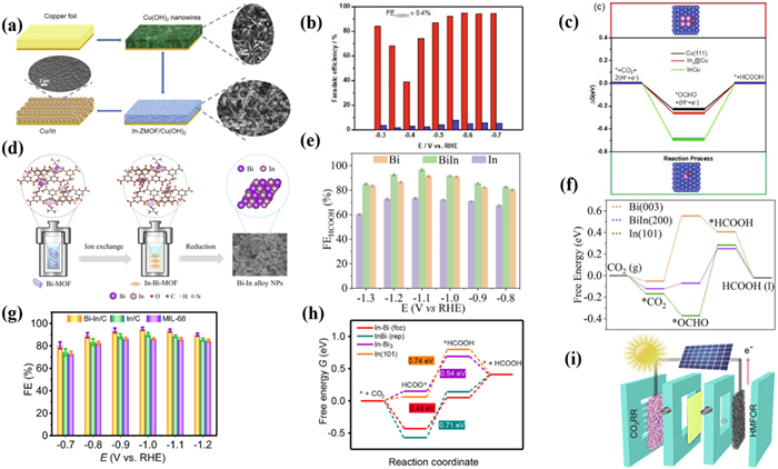
Similarly, Zhang et al. [175] designed an In nanocube Bi-In/C anchored with atomic Bi. HAADF-STEM demonstrated that Bi atoms are uniformly dispersed on the In surface through lattice gap anchoring. Compared with In/C and MIL-68, the maximum FE of Bi-In/C reached 94.2% at −1.0 V with the jHCOOH of −33.6 mA/cm2, and it remained stable during continuous electrolysis for 9 days, far higher than In/C and MIL-68 (Fig. 16g). DFT calculations confirmed that the construction of Bi-In/C materials would adjust the electron distribution on the catalyst surface to reduce the free energy of the reaction intermediates, ultimately facilitating the conversion of *OCHO intermediates to formate (Fig. 16h). In addition, the author utilized solar cells to provide power for the oxidation reactions of CO2RR and 5-hydroxymethylfurfural, achieving the spontaneous generation of formate and FDCA (Fig. 16i). The selectivity of 88.2% for FDCA and the conversion rate of 99.9% for HMF were achieved. Importantly, the FE of HCOOH remained as high as 85.1% after approximately 4 h of electrolysis, demonstrating a highly promising solar fuel conversion.
Heterogeneous structures integrating different functional components can produce synergistic effects to optimize electrocatalytic activity and selectivity [176,177]. In 2020, Zhao et al. [178] obtained In2O3 through pyrolysis of In-MOF, and then partially reduced the original In2O3 electrode to metal In through electro-reduction, forming a nanostructured In/In(Ⅲ) heterostructure with defects (Fig. 17a). Within the entire potential range, the FE value of C1 products, including CO and formate, was close to 100%. This indicated that the In/In(Ⅲ) electrode has excellent selectivity for CO2RR and could significantly inhibit HER under applied potential. FEHCOOH could reach a high value of over 80% at the wide potential range of −0.7 V to −1.2 V, and achieved the maximum FEHCOOH of 93% at −0.8 V (Fig. 17b). The current density remained stable around −15 mA/cm2 at −0.9 V for 25 h. Moreover, the structural analysis indicated that the heterogeneous structure composed of In and In2O3 was well preserved. The author suggested that the synergistic effect between In(0) and In(Ⅲ) is the reason for the excellent electrocatalytic performance (Fig. 17c). Metal In mainly catalyzed the electro-reduction of CO2, while In oxide components further inhibited competition HER, thereby improving CO2RR. Although the construction of In(Ⅲ)/In(0) heterostructures is promising to improve the intrinsic activity of In-based catalysts, the regulation mechanism still needs further clarification.
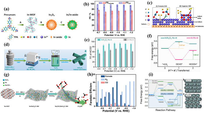
In 2023, He et al. [179] prepared In2O3 hollow nanotubes (In2O3 Ho-nt) by pyrolysis MIL-68(In)-NH2, and then reduced them to In/In2O3 Ho-nt at constant potential (Fig. 17d). The synergistic effect between In(Ⅲ) and In(0) sites was researched. This catalyst can maintain a stable In(0)/In(Ⅲ) heterostructure over a wide potential range during CO2RR. Compared with In/Ho-nt and In2O3 Ho-nt, In/In2O3 Ho-nt exhibited the highest catalytic activity. The maximum FEHCOOH of In/In2O3 Ho-nt was 93% at −0.9 V with the current density of −650 mA/cm2 at −1.2 V (Fig. 17e). It is worth noting that improving the hydrophobicity of GDE by adding PTFE, the MEA device could stably electrolyze for more than 70 h with the current density of −200 mA/cm2 and FEHCOOH over 80%. The author believed that the charge interaction between the In(Ⅲ) and In(0) sites resulted in the concentration of charge density at the In(0) sites and enhanced the intrinsic activity. Results indicated that the electron-deficient environment at the In(0) sites originates from charge redistribution between the In(Ⅲ) and In(0) sites, which promotes the adsorption of *CO2− intermediates and electron transfer kinetics (Fig. 17f). The electronic effect of adjacent two metal atoms provide additional accommodation sites, accelerating the PCET and the desorption of *CO, efficiently improving the performance of CO2RR [180].
In 2021, Gu et al. [181] first conducted DFT calculations to prove that the (101) crystal plane of Sn is more energetically favourable for CO2RR. Subsequently, a variety of Sn/SnO2/C composite with exposed (101) planes was successfully prepared by carbonization and etching of the Sn-MOF precursor at different temperatures (Fig. 17g). The electrochemical results indicated that the Sn(101) crystal surface can promote the catalytic activity. Sn(101)/SnO2/C-500 exhibited a high FEHCOOH of 93.3% at −0.8 V (Fig. 17h), which maintained stability for 20 h. In addition, the author confirmed that the etching conditions can significantly regulate the exposure of Sn(101) crystal planes, thereby affecting the catalytic activity of the material (Fig. 17i).
Xia et al. [182] reported a carbon-confined In2O3@C catalyst derived from MIL-68, which can efficiently produce formate in a solid-state electrolyte (SSE) mediated flow cell directly (Fig. 18a). Pyrolysis of MIL-68(In) was carried out in an Ar environment, and the organic ligand was destroyed and carbonized. On the contrary, ligands will be completely decomposed when heated in air, resulting in the formation of In2O3. Compared to In2O3 derived from pyrolysis of MIL-68 in air, In2O3@C had a higher specific surface area and stronger CO2 adsorption capacity. In2O3@C exhibited the best CO2RR performance with the FEHCOOH over 90% at the wide potential range of −0.8~1.3 V and reached a maximum of 94% at −1.1 V (Fig. 18b). It is worth noting that In2O3@C possessed a higher ECSA, mainly due to the porous structure of carbon coated In oxide inhibiting particle aggregation and enhancing the exposure of active sites. Moreover, the carbon encapsulation and oxygen vacancies alter the d-band center and electronic properties of In2O3, enhancing its affinity for *CO2− intermediates. The author suggested that the carbon layer can protect the In oxide while improving its electrical conductivity, ensuring the timely transfer of electrons to avoid structural changes caused by excessive accumulation of electrons. Afterward, the author utilized porous cation exchange resins as SSE to form the MEA-SSE device for direct production of liquid pure formate solution. A liquid formate solution of approximately 0.12 mol/L could be directly and continuously generated in the MEA-SSE device with a current density of −30 mA/cm2.
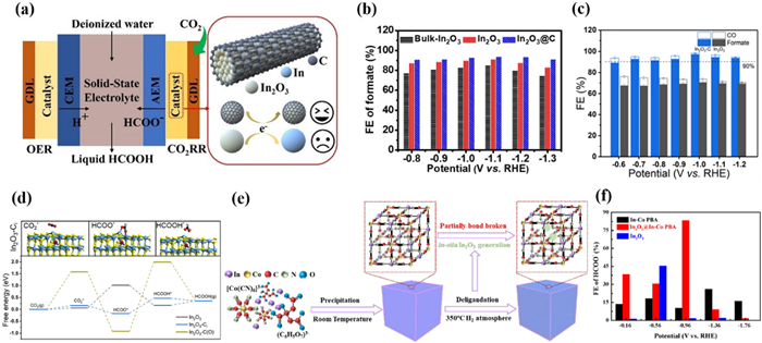
Compared with a carbon coating, direct doping of carbon atoms into the In2O3 lattice is also effective in improving the catalyst performance [183,184]. Wu et al. [185] also synthesized In2O3—C nanorods by pyrolysis of MOF precursor MIL-68(In), exhibiting very high current density and FE. The FE of HCOOH reached 97.2% at −1.0 V, and maintained above 90% within a wide potential range of 500 mV (Fig. 18c). Importantly, the FEHCOOH was maintained at 80.5% with the current density of −1 A/cm2, which corresponds to a jHCOOH of −805 mA/cm2. At the industrial-related current density of −200 mA/cm2, In2O3—C maintained a high FEHCOOH of over 85% for more than 15 h. The author believed that the In2O3-C exhibits such excellent performance because the addition of carbon atoms increased the electronic density of In sites, rebalancing the conductivity and activity of In2O3 for CO2RR. Moreover, the insertion of C atoms into the In2O3 lattice rather than encapsulating the outside with carbon can more effectively regulate the electron density of In atoms, thereby achieving simultaneous regulation of electronic structure and active sites, thus enabling In2O3-C catalysts to have high selectivity and excellent activity (Fig. 18d).
Gao et al. [186] reported a new type of MOF In[Co(CN)6] (In-Co PBA) nanocube, which was transformed through a controlled low-temperature conversion process. The nanocube retained the three-dimensional porous structure of PBA, and contained in situ generated In2O3 nanoparticles in the MOF channel (Fig. 18e). This new structure not only retained the appearance and structure of the original MOF but also had a higher specific surface area and porosity, which is conducive to CO2RR. In2O3@In-Co PBA exhibited better CO2RR performance than In-Co PBA, reaching a FEHCOOH of 85% at −1.9 V (Fig. 18f). The current density of In2O3@In-Co PBA remained stable in 5 h of CO2RR without significant attenuation. No significant reduction of In2O3 was observed, indicating that the In2O3@In-Co PBA quasi-MOF catalyst has good stability. The author suggested that the improved activity of quasi-MOF is mainly attributed to the retained original porous structure, which increases the specific surface area and promotes the dispersion of the In active sites in the pore structure. Atomically dispersed catalytic sites are conducive to the transfer of electrons at the gas-liquid-solid three-phase boundary [131]. In addition, the interaction between the cyanide groups in PBA and In2O3 nanoparticles in the pores facilitates the regulation of the electronic environment of surrounding nanoparticles, thereby stabilizing the HCOO* intermediate obtained through proton-coupled electron transfer and ultimately improving catalytic performance. Generally speaking, the excellent CO2RR performance of In-based catalyst is due to the oxidation state of metal active sites, which can effectively inhibit HER and promote the activation of CO2 [187].
Han et al. [188] synthesized a series of porous In-Cu bimetallic oxide catalysts with different Cu/In ratios (Fig. 19a). By adjusting the ratio of In/Cu in the MOF precursor, selective conversion of CO/H2 could be easily achieved. When the Cu content increased to a Cu/In ratio of 0.92, the maximum FECO of InCuO-0.92 at −0.8 V potential was 92.1% (Figs. 19b and c). The CO2 reduction activity was significantly enhanced, indicating a synergistic effect between In oxide and Cu oxide in the CO generation process. The author proposed that the surprising CO2RR activity of porous In-Cu bimetallic oxides is due to their efficient adsorption of CO2 and faster mass diffusion. In addition, Cu doped into In2O3 creates heterojunction interfaces, enhances CO2 adsorption capacity, and reduces charge transfer resistance.
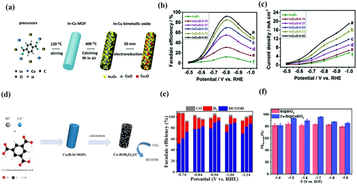
Similarly, Chen's group [189] reported a series of Cu/Bi bimetallic catalysts Cux-Bi/Bi2O3 derived from MOF (Fig. 19d). Cu1-Bi/Bi2O3@C displayed an excellent CO2RR performance after optimized Cu content compared with Bi/Bi2O3@C. Under the condition of external potential −0.94 V, the FE of HCOOH was as high as 93% with a current density of −10.1 mA/cm2 (Fig. 19e). As a result, Cu1-Bi/Bi2O3@C has more active sites and the synergistic effect of Bi/Cu bimetallic can reduce the activation energy barrier of CO2. Meanwhile, the electron transfer between Cu and Bi also regulates the binding strength of the catalyst surface intermediate *CO2−.
Interestingly, in addition to introducing transition metals, doping with rare earth metals may alter the electronic structure of the catalyst, thereby improving its electrocatalytic performance. In 2021, Guo et al. [190] synthesized Ce-doped Bi-MOFs using a modified method, resulting in a carbon-supported bimetallic nanocomposite material with a core-shell structure (Ce-Bi@CeBiOx/C). XPS spectra showed that some electrons in Bi(Ⅲ) transfer from Bi to Ce, indicating that the electronic structure of Bi is adjusted by the strong interaction of Ce, leading to more O vacancies in the material after Ce doping. The FEHCOOH of Ce-Bi@CeBiOx/C was maintained above 80% within the wide potential range of −1.4 V to −1.9 V, with a maximum FEHCOOH of 96% (Fig. 19f). During the 10 h electrolysis process, the total current density and the FEHCOOH did not significantly decrease. The author believed that the surprising activity of Ce-Bi@CeBiOx/C contributed to Ce doped core-shell structure. On the one hand, surface defects of O vacancies can create an electron rich environment, promoting the adsorption of CO2 by O vacancies. On the other hand, the changes in electronic structure may benefit the electron transfer from the more electronegative O atom to the Bi atom, enhancing the adsorption of HCOO* intermediates, thereby improving the activity of CO2RR to generate formate.
In 2020, Xia et al. [191] prepared a carbon nanotube encapsulated Bi oxide (Bi2O3@C) derived from a Bi-MOF (Fig. 20a). A series of derivatives were obtained by controlling the carbonization conditions, of which Bi2O3@C-800 exhibited the best CO2RR performance with FEHCOOH of 93% at −0.28 V (Fig. 20b). Bi2O3@C-800 had higher formate selectivity, lower resistance, and higher current density compared with Bi2O3@C-600, Bi@C-600, and Bi@C-800. The author believed that the excellent performance contributed to the synergistic effect originating from the special structure of Bi2O3 encapsulated in a carbon matrix, Bi2O3 contributes to the improvement of selectivity and reaction kinetics while the carbon substrate facilitates the increase of current density.

In addition, the oxygen-rich Bi surface can also significantly promote reaction kinetics and increase the activity of CO2RR. Because Bi-O species promote the adsorption of CO2 and the formation of *OCHO intermediates [192,193]. In 2022, Chen's group [194] prepared an oxygen-rich Bi@C nanoparticles (SOR Bi@C NPs) derived from SU-101 MOF. SOR Bi@C NPs achieved a high FEHCOOH of over 91% within the potential range of 440 mV, achieving a high jHCOOH of −140.5 mA/cm2 (Fig. 20c). The average FE of SOR Bi@C NPs during continuous electrolysis for 18 h exceeded 92%. After CO2RR, Bi-O species were partially reduced to form coexisting substances consisting of Bi and Bi-O in SOR Bi@CNPs. However, the Bi-O species still remained dominant and persistent, indicating the stability of the catalysts. DFT calculations suggested that the Bi-O/Bi(110) structure is beneficial for adsorbing CO2 and generating *OCHO intermediates, which is the origin of promising CO2RR activity of SOR Bi@CNPs (Fig. 20d).
Except for improving the catalytic performance of CO2RR with bimetallic catalysts, doping non-metallic elements into metal catalysts also has an encouraging effect. In 2022, Gao et al. [195] prepared a catalyst BS@Cx (x represents temperature) with uniformly dispersed stable active sites by sulfurizing Bi-BTC with thioacetamide (Fig. 20e). The Bi-S motif unit underwent modification with the increase of calcination temperature and gradually stabilized at high temperature. It is worth noting that unlike other Bi-based catalysts, BS@Cx exhibited excellent selectivity of methanol CO2RR. Under the condition of −0.9 V, the maximum FE of BS@C800 for methanol and the selectivity of methanol reached 78.6% and 78.8%, respectively (Fig. 20f). After 12 h of continuous electrolysis, the FE and current density had not significantly decreased, proving the good stability of BS@Cx. The author proposed that the main product of CO2RR changes from HCOOH to methanol is due to the special Bi-S motif. Doping S atoms to create the Bi-S motif changes the adsorption capacity of the original intermediate, resulting in the easier dehydroxylation of the formate intermediate (COOH*) and stronger stability of CO on the surface of the Bi-S motif. As a result, the key intermediate CH2O* was generated and further reduced to methanol.
Single-atom catalysts have been proven to be potential catalysts for CO2RR [196-199]. When the catalyst is dispersed into a single atom form, the electron distribution and atomic structures of the active components will undergo significant changes, which may lead to some performance advantages for catalytic applications [109]. In addition, studies have shown that single-atom catalysts with metal nitrogen (M-Nx) modified carbon-based structures can serve as ideal CO2RR electrocatalysts [200,201]. Especially, the four coordinated structures (M-N4) may be a favorable catalytic site for M-Nx catalysts [202,203].
In 2020, Li et al. [109] designed a new In-MOF derivative for CO2RR, there were exclusive Inδ+-N4 interface groups on the N-doped carbon matrix (In-SAs/NC) derived from MOFs (Fig. 21a). The FEHCOO− of In-SAs/NC over than 85% in the wide potential range (−0.65~0.95 V) with the maximum value of 96% at −0.65 V (Fig. 21b). DFT results suggested that In has the lowest free energy for generating HCOO* due to the presence of the Inδ+-N4 interface compared to In-NPs/NC and NC. In addition, other M-Nx structures also exhibit unique catalytic activity (Fig. 21c). In 2021, Yin et al. [204] reported a catalyst with atomically dispersed In sites using an In/Zn zeolite imidazole framework as a template, which exhibited surprising catalytic performance in the conversion of CO2 to HCOOH (Fig. 21d). The In-N-C prepared at high temperatures retained the porous structure of the original ZIF-8. During the CO2RR process, the oxidation state of In in In-N-C can remain unchanged instead of being electrochemically reduced to metal In as in In2O3 as evidenced by XPS. This confirmed that the coordination of In to N shows better stability compared to the coordination to O. In-N-C achieved a maximum FEHCOOH of 80% at −0.79 V (Fig. 21e). DFT calculations suggested that dispersed In atoms have strong electronic interactions with adjacent N atoms, which could effectively convert CO2 to formate. The low energy barrier of the formation of *OCHO intermediates promotes the reduction of CO2 to formate (Fig. 21f).
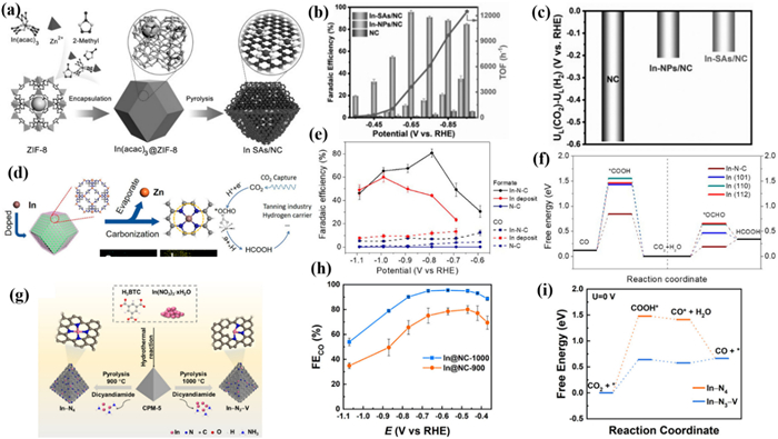
In 2022, K. Daasbjerg and Liu et al. [205] reported two In-MOF derivatives, In@NC-900 and In@NC-1000, with a typical In-N4 coordination structure and a low coordination In-N3-V structure containing vacancies, respectively (Fig. 21g). Compared to In@NC-900, the In@NC-1000 generated more CO at −0.57 V with a maximum FECO of 95% (Fig. 21h). And during the 14 h CO2RR process, the In-N3-V coordination environment and active site distribution in In@NC-1000 were not changed, resulting in stable FE and current density. DFT calculations found that the orbitals energy of In atoms in In-N3-V is higher than that of In-N4, therefore closer to Fermi energy. This phenomenon is more pronounced in the hybrid s orbitals and pz orbitals of In atoms, which is the main reason for the improvement of CO2RR performance by catalysts of In@NC-1000. At the same time, In-N3-V can reduce the energy barrier of COOH* adsorbed on In sites, resulting in excellent selectivity for CO (Fig. 21i).
Huang et al. [206] prepared a series of In SACs with MIL-68 as a precursor assisted by dicyandiamide, and customized the coordination environment of In centers by changing the annealing temperature (Fig. 22a). Specifically, In SACs with In-NxC4-x local coordination structures were successfully synthesized. Importantly, the selectivity of formate and CO can be adjusted by changing the proportion of C and N. CO is the only product for In SACs-1000 with FECO up to 97% at −0.6 V. For the In SACs-800, both HCOOH (38% at −0.9 V) and CO (52% at −0.5 V) were detected simultaneously (Fig. 22b). And the main product of In2O3 NPs was HCOOH with the FEHCOOH of 67.8% at −0.8 V. These experimental data suggested that In SACs have significant product selectivity and the coordination structure has an important impact on the CO2RR reaction pathway. And under a current of −0.4 A in MEA, it worked continuously for 60 h with a FECO over 90%, indicating excellent stability. DFT calculations suggested that the In sites in In SACs are active for the electro-reduction of CO2 into formate, while the carbon atoms adjacent to In tend to follow the conversion pathway from CO2 to CO (Fig. 22c). Due to the increase in annealing temperature, the proportion of carbon atoms increased. Therefore, the satisfactory CO2RR performance of In SACs-1000 is achieved by switching the active site from the In site to the neighboring C atom. This work provides new insights into the practical catalytic active sites in SAC materials.
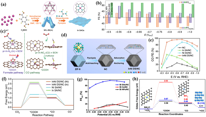
In addition to single-atom catalysts, constructing heteronuclear double single-atom catalysts is also a promising CO2RR strategy. In 2023, Hou et al. [207] designed an atomically dispersed InNi dual-site catalyst (InNi DS/NC) anchored on nitrogen carbon derived from zeolite imidazole frameworks. Bridged by an axial oxygen atom, In and Ni atoms build a unique O-In-N6Ni unit (Fig. 22d). InNi DS/NC exhibited the best catalytic performance with the highest FECO of 96.7% at −0.7 V which was significantly better than In DS/NC and Ni DS/NC (Fig. 22e). The catalytic performance of InNi DS/NC could be maintained over 9 h at a high current density of −317.2 mA/cm2 in 1 mol/L KOH. DFT calculations suggested that the CO selectivity of In active sites was improved by the incorporation of adjacent Ni atoms. Moreover, Ni and In can synergistically contribute to CO production via bridging O atoms (Fig. 22f).
In 2019, Li et al. [48] designed an N- doped carbon network catalyst (Bi SAs/NC) composed of single Bi atoms, with a Bi-N4 structure as the active sites to promote the CO2RR. The author obtained the Bi-N4 sites on porous carbon networks through the pyrolysis of Bi-MOF with DCD. DCD played a crucial role in redispersing Bi atoms and immobilizing Bi atoms in defects. Interestingly, unlike most Bi-based catalysts, Bi SAs/NC exhibited excellent selectivity for CO with FECO up to 97% at −0.5 V (Fig. 22g). Bi SAs/NC remained stable after a long-term electrolysis process of 4 h, further confirming its good stability. DFT calculations suggested that Bi-N4/C active sites have a lower energy barrier for the generation of *COOH intermediate, resulting in unique selectivity and better CO2RR performance (Fig. 22h).
MOF derivative catalysts can improve the stability and conductivity of the catalysts while retaining the structure of the original MOF precursor, thereby significantly enhancing the CO2RR performance. However, how to obtain MOF derivatives with expected structures through design and synthesis methods is still the focus of current research. The p-block meatal-based MOF-derived catalysts for CO2RR have been listed in Table 3.
DownLoad:
CSV
| Electrocatalyst | Electrolysis device | Electrolyte | Main product | FEmax (%) | jmain product at FEmax (mA/cm2) | Potential (V vs. RHE) | Ref. |
| In/In oxide | H-type cell | 0.5 mol/L KHCO3 | HCOOH | 93 | / | −1.1 | [178] |
| In/In2O3 Ho-nt | Flow cell | 1 mol/L KOH | HCOOH | 93 | / | −0.9 | [179] |
| MEA | 0.1 mol/L KOH (MEA) | HCOOH | 90.6 | 150 | / | ||
| Sn(101)/SnO2/C-500 | H-type cell | 0.5 mol/L KHCO3 | HCOOH | 93.3 | 8.2 | −0.8 | [181] |
| InCuO-0.92 | H-type cell | 0.5 mol/L KHCO3 | CO | 92.1 | / | −0.8 | [188] |
| In-Bi alloy NPs | Flow cell | 1 mol/L KOH | HCOOH | 97.8 | 250 | / | [174] |
| Cu1-Bi/Bi2O3@C | H-type cell | 0.5 mol/L KHCO3 | HCOOH | 93 | 10.1 | −0.94 | [189] |
| Ce-Bi@CeBiOx/C | H-type cell | 0.5 mol/L KHCO3 | HCOOH | 96 | / | −1.7 | [190] |
| In2O3@C | Flow cell | 1 mol/L KOH | HCOOH | 94 | / | −1.1 | [182] |
| In2O3—C | Flow cell | 1 mol/L KOH | HCOOH | 80.5 | 1000 | / | [185] |
| In-Co PBA | H-type cell | 0.1 mol/L KHCO3 | HCOOH | 85 | / | −0.96 | [186] |
| Bi2O3@C-800 | Flow cell | 1 mol/L KOH | HCOOH | 93 | / | −0.28 | [191] |
| SOR Bi@CNPs | Flow cell | 1 mol/L KOH | HCOOH | 90 | 100 | −1.12 | [194] |
| BiS@C800 | H-type cell | 0.1 mol/L KHCO3 | CH3OH | 78.6 | / | −0.9 | [195] |
| In-SAs/NC | H-type cell | 0.5 mol/L KHCO3 | HCOOH | 96 | 8.87 | −0.65 | [109] |
| In—N—C | H-type cell | 0.5 mol/L KHCO3 | HCOOH | 80 | 6.8 | −0.79 | [204] |
| In@NC-1000 | H-type cell | 0.5 mol/L KHCO3 | CO | 95 | / | −0.57 | [205] |
| In SACs-1000 | H-type cell | 0.5 mol/L KHCO3 | CO | 97 | / | −0.6 | [206] |
| InNi DS/NC | H-type cell | 0.5 mol/L KHCO3 | CO | 96.7 | / | −0.7 | [207] |
| Bi SAs/NC | H-type cell | 0.1 mol/L NaHCO3 | CO | 97 | 5.1 | −0.5 | [48] |
| Cu/In | H-type cell | 0.1 mol/L KHCO3 | CO | 95 | / | −0.6 | [173] |
| Bi-In/C | H-type cell | 0.5 mol/L KHCO3 | HCOOH | 94.2 | 33.6 | −1.0 | [175] |
Electro-reduction of carbon dioxide into valuable chemicals has become a prospective strategy to meet environmental and energy challenges. P-block metals have been proven to have a high affinity for *OCHO due to their unique electronic orbitals and oxygen affinity, making them an environmentally friendly and economically feasible efficient CO2RR electrocatalyst. Therefore, MOF materials constructed based on p-block metals have been emphasized in the field of electrocatalytic CO2 reduction to formic acid. In this review, we summarized the latest progress in the electrocatalytic CO2 field of p-block metal-based MOFs (In, Bi, Sn, Al, Pb, Ga) and MOF-derived catalysts. The catalyst structures, modification strategies, catalytic mechanisms, and structure-activity relationships were discussed. However, although p-block metal-based MOFs and MOF-derived catalysts have exhibited good potential in the CO2RR field, most of them are still difficult to meet the demands of practical applications. Thus, further development of high-performance p-block metal-based MOFs and MOF-derived catalysts remains crucial, challenges and promising research directions can be considered in future research:
(1) At present, lower conductivity and stability are still the main problems that limit the catalytic performance of most p-block metal-based MOFs. The low conductivity restricts the charge transfer of the reaction process while increasing the energy consumption of the reaction. Although the introduction of conductive species and the use of 2D-conducting MOFs have been reported to improve electrical conductivity, the related issues still need further investigation. The construction of complex catalysts is a convenient route. By introducing conducting supports such as graphene, MXene, MBene, the charge transfer during the reaction can be promoted on the one hand, and the hierarchical structure can be constructed on the other hand to promote the enrichment of the substrate. In addition, ligands with redox units have also exhibited promising performance in facilitating charge transfer during the reaction. More p-block metal-based MOFs constructed based on naphthalenediimide-based ligands, tetrathiafulvalene-based ligands, diphenylenedicarboxamido, etc. should be constructed and explored for their application in the field of CO2RR.
(2) Meanwhile, the stability of MOFs themselves also greatly affects the mechanism exploration and practical application of catalysts. Due to the oxyphilic nature of the p-block metal, most of these MOF materials are constructed based on carboxylic acid ligands, whose coordination bonds are difficult to adapt to the CO2RR environment. The introduction of N coordination sites involved in coordination to form metal-N structure can effectively improve the stability of MOFs, especially in the usually basic conditions of CO2RR. However, a rational design of ligand conformation is necessary to overcome the difficulties in synthesizing this class of MOFs. In addition, the stability of the frameworks can also be enhanced by introducing π-π or d-π interactions through rational structural design. Finally, enhancing the hydrophobicity of MOFs likewise prevents the coordination bonds from being attacked to improve the stability of the catalyst. The change of wettability can also modulate the gas and liquid mass transport during the reaction to improve the catalytic performance. Therefore, the potential of hydrophobic MOF materials in the field of CO2RR should be further explored.
(3) Furthermore, MOF-derived catalysts can significantly improve conductivity and stability based on inheriting the original structure of MOFs, which seems to be expected to be promising CO2RR catalysts. However, due to the small variety of p-block metal-based MOF materials themselves compared to transition metal-based MOFs, only a limited number of classical structures have been used as precursors to prepare MOF-derived catalysts. Therefore, the variety of precursors should be further expanded to prepare more efficient catalysts. Moreover, current transformation methods include pyrolysis, acid/base etching, laser metallurgy, sulfidation, phosphitylation, etc., which are not mild enough to preserve the inherent structural features of MOFs. Therefore, milder conversion strategies should be developed to allow the derivative catalysts to preserve the structural advantages of MOFs as much as possible.
(4) Moreover, in addition to the catalyst itself, factors such as the electrolyte, and electrolysis device in the reaction system likewise determine the prospects for CO2RR applications. Currently, alkaline electrolytes have been widely used as electrolytes to obtain better catalytic selectivity. However, since CO2 dissolves in the alkaline electrolyte, leading to higher energy consumption with lower CO2 utilization. Acid electrolytes became an effective solution to the problem. However, very few p-block metal-based MOF catalysts have been reported for their catalytic activity under acidic conditions, and more efforts should be devoted to exploring their potential under such conditions. For the electrolysis device, the MEA-SSE device becomes desirable as the reduction product of the p-block metal-based catalyst is dominated by formic acid [182]. Pure formic acid solutions can be obtained by rinsing the layer of solid-state electrolyte with pure water or N2 gas streams, which significantly reduces the separation cost of the product. However relevant reports are equally lacking and the variety of solid-state electrolytes should be expanded to improve the transfer efficiency.
(5) Finally, exploring the CO2RR reaction process is also one of the current major challenges. At present, the role of catalyst molecules on the electrode surface and the reaction pathway during the CO2RR process is based on the binding energy between intermediates and the electrode surface and active sites, which rely on theoretical simulation calculations. Although the morphology, structure, and valence state changes of catalyst molecules after electro-reactions can be obtained through common surface characterization techniques, real-time monitoring during the CO2RR process relies on in situ/operational characterization techniques. There is a lack of relevant knowledge and monitoring methods regarding the surface coverage and electrochemical active area of catalyst molecules, as well as the chemical state and true structure of MOFs and MOF-derived catalysts during the CO2RR process. According to current mechanism research, the entire CO2RR process involves a series of electron transfer proton coupling processes and complex mass transfer processes. More in-depth in situ/operando characterization techniques are needed to monitor the reaction microenvironment in real time, which can serve as an experimental basis to combine with DFT calculations for further unraveling the reaction mechanism.
The authors declare that they have no known competing financial interests or personal relationships that could have appeared to influence the work reported in this paper.
Xinyu Wu: Writing – original draft, Resources, Investigation. Jianfeng Lu: Writing – original draft. Zihao Zhu: Writing – review & editing, Resources, Project administration, Funding acquisition. Suijun Liu: Writing – review & editing, Project administration. Herui Wen: Project administration.
This work was supported by the National Natural Science Foundation of China (Nos. 22061019 and 22261021), the Jiangxi Provincial Natural Science Foundation (Nos. 20224BAB203002, 20232ACB203018, 20232BAB203005, and 20224BAB213001), the Jiangxi Province Key Laboratory of Functional Crystalline Materials Chemistry (No. 2024SSY05161), the Ganzhou Key Research and Development Program (No. 2023PNS26963), the Youth Jinggang Scholars Program in Jiangxi Province (No. QNJG2019053), the Two Thousand Talents Program in Jiangxi Province (No. jxsq2019201068), the Doctor's Starting Research Foundation of Jiangxi University of Science and Technology (No. 205200100597), and the Science and Technology Research Project of Jiangxi Provincial Department of Education (No. GJJ2200860).
T. Zheng, K. Jiang, H. Wang, Adv. Mater. 30 (2018) 1802066.
H. Zhao, D. Benetti, X. Tong, et al., Nano Energy 50 (2018) 756–765.
H. Zhao, G. Liu, S. You, et al., Energy Environ. Sci. 14 (2021) 396–406. doi: 10.1039/d0ee02235g
S. Chu, A. Majumdar, Nature 488 (2012) 294–303. doi: 10.1038/nature11475
Q. Hu, W. Zhou, S. Qi, et al., Nat. Sustain. 7 (2024) 442–451. doi: 10.1038/s41893-024-01302-0
X.L. Jiang, F.Y. Ren, Y. Shi, et al., CCS Chem. 6 (2024) 2333–2345. doi: 10.31635/ccschem.024.202303476
L. Li, Y. Huang, Y. Li, Energy Chem. 2 (2020) 100024.
D. Li, M. Kassymova, X. Cai, et al., Coord. Chem. Rev. 412 (2020) 213262.
M. Reichstein, M. Bahn, P. Ciais, et al., Nature 500 (2013) 287–295. doi: 10.1038/nature12350
D. Notz, J. Stroeve, Science 354 (2016) 747–750. doi: 10.1126/science.aag2345
C. Hepburn, E. Adlen, J. Beddington, et al., Nature 575 (2019) 87–97. doi: 10.1038/s41586-019-1681-6
C. Vogt, M. Monai, G.J. Kramer, et al., Nat. Catal. 2 (2019) 188–197. doi: 10.1038/s41929-019-0244-4
H. Xu, D. Rebollar, H. He, et al., Nat. Energy 5 (2020) 623–632.
R.L. Siegelman, E.J. Kim, J.R. Long, Nat. Mater. 20 (2021) 1060–1072. doi: 10.1038/s41563-021-01054-8
P.V. Kortunov, M. Siskin, L.S. Baugh, et al., Energy Fuels 29 (2015) 5940–5966. doi: 10.1021/acs.energyfuels.5b00985
J. Palomar, M. Larriba, J. Lemus, et al., Sep. Purif. Technol. 213 (2019) 578–586.
X. Duan, J. Xu, Z. Wei, et al., Adv. Mater. 29 (2017) 1701784.
K.T. Ngo, M. McKinnon, B. Mahanti, et al., J. Am. Chem. Soc. 139 (2017) 2604–2618. doi: 10.1021/jacs.6b08776
D. Xiang, D. Magana, R.B. Dyer, J. Am. Chem. Soc. 136 (2014) 14007–14010. doi: 10.1021/ja5081103
A. Otto, T. Grube, S. Schiebahn, et al., Energy Environ. Sci. 8 (2015) 3283–3297.
H. Rao, J. Bonin, M. Robert, J. Phys. Chem. C 122 (2018) 13834–13839. doi: 10.1021/acs.jpcc.8b00950
S. Dou, L. Tao, R. Wang, et al., Adv. Mater. 30 (2018) 1705850.
Y. Lum, J.W. Ager, Nat. Catal. 2 (2019) 86–93.
Z. Miao, P. Hu, C. Nie, et al., J. Energy Chem. 38 (2019) 114–118.
A.M. Appel, J.E. Bercaw, A.B. Bocarsly, et al., Chem. Rev. 113 (2013) 6621–6658. doi: 10.1021/cr300463y
Y.Y. Zhang, G.W. Yang, R. Xie, et al., Angew. Chem. Int. Ed. 59 (2020) 23291–23298. doi: 10.1002/anie.202010651
Y. Zhang, H. Liu, F. Gao, et al., Energy Chem. 4 (2022) 100078.
Q. Gong, P. Ding, M. Xu, et al., Nat. Commun. 10 (2019) 2807.
D.U. Nielsen, X.M. Hu, K. Daasbjerg, et al., Nat. Catal. 1 (2018) 244–254. doi: 10.1038/s41929-018-0051-3
W. Li, H. Wang, X. Jiang, et al., RSC Adv. 8 (2018) 7651–7669. doi: 10.1039/c7ra13546g
J. Xiong, J. Di, J. Xia, et al., Adv. Funct. Mater. 28 (2018) 1801983.
Q. Han, X. Bai, Z. Man, et al., J. Am. Chem. Soc. 141 (2019) 4209–4213. doi: 10.1021/jacs.8b13673
S. Xu, E.A. Carter, Chem. Rev. 119 (2019) 6631–6669. doi: 10.1021/acs.chemrev.8b00481
L. Zhang, Z.J. Zhao, J. Gong, Angew. Chem. Int. Ed. 56 (2017) 11326–11353. doi: 10.1002/anie.201612214
S.L. Xie, J. Liu, L.Z. Dong, et al., Chem. Sci. 10 (2019) 185–190. doi: 10.1039/c8sc03471k
K.L. Bae, J. Kim, C.K. Lim, et al., Nat. Commun. 8 (2017) 1156.
X. Li, C. Deng, Y. Kong, et al., Angew. Chem. Int. Ed. 62 (2023) e202309732.
C.J. Yang, L. Liu, Q.S. Gu, et al., CCS Chem. 6 (2024) 1612–1627. doi: 10.31635/ccschem.024.202403839
Q. Hu, S. Qi, Q. Huo, et al., J. Am. Chem. Soc. 146 (2024) 2967–2976. doi: 10.1021/jacs.3c06904
Z. Yang, F.E. Oropeza, K.H.L. Zhang, APL Mater 8 (2020) 060901.
A.S. Varela, W. Ju, P. Strasser, Adv. Energy Mater. 8 (2018) 1703614.
C. Chen, J.F. Khosrowabadi Kotyk, S.W. Sheehan, Chem. 4 (2018) 2571–2586.
C. Wei, S. Sun, D. Mandler, et al., Chem. Soc. Rev. 48 (2019) 2518–2534. doi: 10.1039/c8cs00848e
P. Shao, L. Yi, S. Chen, et al., J. Energy Chem. 40 (2020) 156–170.
D. Li, L. Huang, Y. Tian, et al., Appl. Catal. B 292 (2021) 120119.
S. Liu, J. Xiao, X.F. Lu, et al., Angew. Chem. Int. Ed. 58 (2019) 8499–8503. doi: 10.1002/anie.201903613
L. Ji, L. Chang, Y. Zhang, et al., ACS Catal. 9 (2019) 9721–9725. doi: 10.1021/acscatal.9b03180
E. Zhang, T. Wang, K. Yu, et al., J. Am. Chem. Soc. 141 (2019) 16569–16573. doi: 10.1021/jacs.9b08259
S. Roy, B. Sharma, J. Pécaut, et al., J. Am. Chem. Soc. 139 (2017) 3685–3696. doi: 10.1021/jacs.6b11474
X. Yang, Q.X. Li, S.Y. Chi, et al., SmartMat 3 (2022) 163–172.
M.R. Liu, Q.L. Hong, Q.H. Li, et al., Adv. Funct. Mater. 28 (2018) 1801136.
Y.X. Tan, F. Wang, J. Zhang, Chem. Soc. Rev. 47 (2018) 2130–2144. doi: 10.1039/c7cs00782e
H. Furukawa, K.E. Cordova, M. O'Keeffe, et al., Science 341 (2013) 1230444.
C.S. Diercks, Y. Liu, K.E. Cordova, et al., Nat. Mater. 17 (2018) 301–307. doi: 10.1038/s41563-018-0033-5
T. Qiu, S. Gao, Z. Liang, et al., Angew. Chem. Int. Ed. 60 (2021) 17314–17336. doi: 10.1002/anie.202012699
Z. Meng, Z. Qiu, Y. Shi, et al., eScience 3 (2023) 100092.
Z. Jiao, X. Zhao, J. Zhao, et al., Acta Phys. Chim. Sin. 39 (2023) 2301018. doi: 10.3866/pku.whxb202301018
G.L. Yang, Y. Xie, Z.H. Jiao, et al., J. Mater. Chem. A 11 (2023) 16255–16262. doi: 10.1039/d3ta02520a
Y. Lv, S.W. Ke, Y. Gu, et al., Angew. Chem. Int. Ed. 62 (2023) e202305246.
Z. Lei, Y. Xue, W. Chen, et al., Adv. Energy Mater. 8 (2018) 1801587.
Z.G. Gu, J. Zhang, Coord. Chem. Rev. 378 (2019) 513–532.
R.S. Kumar, S.S. Kumar, M.A. Kulandainathan, Electrochem. Commun. 25 (2012) 70–73.
R. Hinogami, S. Yotsuhashi, M. Deguchi, et al., ECS Electrochem. 1 (2012) H17–H19. doi: 10.1149/2.001204eel
T. Ma, Q. Fan, H. Tao, et al., Nanotechnology 28 (2017) 472001. doi: 10.1088/1361-6528/aa8f6f
S. Zhang, P. Kang, S. Ubnoske, et al., J. Am. Chem. Soc. 136 (2014) 7845–7848. doi: 10.1021/ja5031529
Z. Chen, K. Mou, S. Yao, et al., J. Mater. Chem. A 6 (2018) 11236–11243. doi: 10.1039/c8ta03328e
Z.H. Zhao, J.R. Huang, D.S. Huang, et al., J. Am. Chem. Soc. 146 (2024) 14349–14356. doi: 10.1021/jacs.4c04841
P. Li, F. Yang, J. Li, et al., Adv. Energy Mater. 13 (2023) 2301597.
N.V. Rees, R.G. Compton, J. Solid State Electrochem. 15 (2011) 2095–2100. doi: 10.1007/s10008-011-1398-4
A. Liu, M. Gao, X. Ren, et al., J. Mater. Chem. A 8 (2020) 3541–3562. doi: 10.1039/c9ta11966c
R. Francke, B. Schille, M. Roemelt, Chem. Rev. 118 (2018) 4631–4701. doi: 10.1021/acs.chemrev.7b00459
D.D. Zhu, J.L. Liu, S.Z. Qiao, Adv. Mater. 28 (2016) 3423–3452. doi: 10.1002/adma.201504766
A. Vasileff, Y. Zheng, S.Z. Qiao, Adv. Energy Mater. 7 (2017) 1700759.
J. Zhang, W. Cai, F.X. Hu, et al., Chem. Sci. 12 (2021) 6800–6819. doi: 10.1039/d1sc01375k
T. Cheng, H. Xiao, W.A. Goddard, J. Ⅲ, Am. Chem. Soc. 138 (2016) 13802–13805. doi: 10.1021/jacs.6b08534
S. Jin, Z. Hao, K. Zhang, et al., Angew. Chem. Int. Ed. 60 (2021) 20627–20648. doi: 10.1002/anie.202101818
S. Guo, T. Asset, P. Atanassov, ACS Catal. 11 (2021) 5172–5188. doi: 10.1021/acscatal.0c04862
T. Tang, Z. Wang, J. Guan, Adv. Funct. Mater. 32 (2022) 2111504.
J. Yu, J. Wang, Y. Ma, et al., Adv. Funct. Mater. 31 (2021) 2102151.
H.H. Cramer, B. Chatterjee, T. Weyhermüller, et al., Angew. Chem. Int. Ed. 132 (2020) 15804–15811. doi: 10.1002/ange.202004463
Y. Fang, J.C. Flake, J. Am. Chem. Soc. 139 (2017) 3399–3405. doi: 10.1021/jacs.6b11023
Z. Gao, Y. Gong, Y. Zhu, et al., Nano Res. 16 (2023) 8743–8750. doi: 10.1007/s12274-023-5685-z
Y. Hori, K. Kikuchi, S. Suzuki, Chem. Lett. 14 (1985) 1695–1698. doi: 10.1246/cl.1985.1695
Y. Hori, A. Murata, Electrochim. Acta 35 (1990) 1777–1780.
Y. Hori, H. Wakebe, T. Tsukamoto, et al., Electrochim. Acta 39 (1994) 1833–1839.
M. Jouny, W. Luc, F. Jiao, Ind. Eng. Chem. Res. 57 (2018) 2165–2177. doi: 10.1021/acs.iecr.7b03514
L. Yuan, S. Zeng, X. Zhang, et al., Mater. Rep. Energy 3 (2023) 100177.
Z.W. Seh, J. Kibsgaard, C.F. Dickens, et al., Science 355 (2017) eaad4998.
A.J. Welch, J.S. DuChene, G. Tagliabue, et al., ACS Appl. Energy Mater. 2 (2019) 164–170. doi: 10.1021/acsaem.8b01570
E.E. Benson, C.P. Kubiak, A.J. Sathrum, et al., Chem. Soc. Rev. 38 (2009) 89–99.
P. Kang, Z. Chen, M. Brookhart, et al., Top. Catal. 58 (2015) 30–45. doi: 10.1007/s11244-014-0344-y
R.Z. Zhang, B.Y. Wu, Q. Li, et al., Coord. Chem. Rev. 422 (2020) 213436.
N. Han, P. Ding, L. He, et al., Adv. Energy Mater. 10 (2020) 1902338.
S. Verma, B. Kim, H.R.M. Jhong, et al., ChemSusChem 9 (2016) 1972–1979. doi: 10.1002/cssc.201600394
W. Lai, Y. Qiao, J. Zhang, et al., Energy Environ. Sci. 15 (2022) 3603–3629. doi: 10.1039/d2ee00472k
J. Zhao, S. Xue, J. Barber, et al., J. Mater. Chem. A 8 (2020) 4700–4734. doi: 10.1039/c9ta11778d
X. Tan, C. Yu, Y. Ren, et al., Energy Environ. Sci. 14 (2021) 765–780. doi: 10.1039/d0ee02981e
R. Peters, M. Baltruweit, T. Grube, et al., J. CO2 Util. 34 (2019) 616–634.
Y. Wang, T. He, J. Mater. Chem. A 9 (2021) 87–110.
L. Gao, X. Cui, C.D. Sewell, et al., Chem. Soc. Rev. 50 (2021) 8428–8469. doi: 10.1039/d0cs00962h
Z. Wang, P. Hou, Y. Wang, et al., ACS Sustain. Chem. Eng. 7 (2019) 6106–6112. doi: 10.1021/acssuschemeng.8b06278
Y. Liu, C.C.L. McCrory, Nat. Commun. 10 (2019) 1683.
J.A. Rabinowitz, M.W. Kanan, Nat. Commun. 11 (2020) 5231.
J.E. Huang, F. Li, A. Ozden, et al., Science 372 (2021) 1074–1078. doi: 10.1126/science.abg6582
S. Chatterjee, I. Dutta, Y. Lum, et al., Energy Environ. Sci. 14 (2021) 1194–1246. doi: 10.1039/d0ee03011b
Y. Pei, H. Zhong, F. Jin, Energy Sci. Eng. 9 (2021) 1012–1032. doi: 10.1002/ese3.935
A. Bagger, W. Ju, A.S. Varela, et al., ChemPhysChem 18 (2017) 3266–3273. doi: 10.1002/cphc.201700736
Y.X. Du, Y.T. Zhou, M.Z. Zhu, Tungsten 5 (2023) 201–216. doi: 10.1007/s42864-022-00197-8
H. Shang, T. Wang, J. Pei, et al., Angew. Chem. Int. Ed. 132 (2020) 22651–22655. doi: 10.1002/ange.202010903
W. Luo, W. Xie, M. Li, et al., J. Mater. Chem. A 7 (2019) 4505–4515. doi: 10.1039/c8ta11645h
B. Jia, Z. Chen, C. Li, et al., J. Am. Chem. Soc. 145 (2023) 14101–14111. doi: 10.1021/jacs.3c04288
J. Zhang, R. Yin, Q. Shao, et al., Angew. Chem. Int. Ed. 58 (2019) 5609–5613. doi: 10.1002/anie.201900167
W. Ma, S. Xie, X.G. Zhang, et al., Nat. Commun. 10 (2019) 892.
Y.Y. Birdja, R.E. Vos, T.A. Wezendonk, et al., ACS Catal. 8 (2018) 4420–4428. doi: 10.1021/acscatal.7b03386
Z.H. Zhu, Z.L. Liang, Z.H. Jiao, et al., Angew. Chem. Int. Ed. 61 (2022) e202214243.
S.Z. Hou, X.D. Zhang, W.W. Yuan, et al., Inorg. Chem. 59 (2020) 11298–11304. doi: 10.1021/acs.inorgchem.0c00769
X. Kang, L. Li, A. Sheveleva, et al., Nat. Commun. 11 (2020) 5464.
L.L. Zhuo, P. Chen, K. Zheng, et al., Angew. Chem. Int. Ed. 61 (2022) e202204967.
S. Wang, Y. Wang, J.M. Huo, et al., Inorg. Chem. Front. 10 (2023) 158–167.
X. Kang, B. Wang, K. Hu, et al., J. Am. Chem. Soc. 142 (2020) 17384–17392. doi: 10.1021/jacs.0c05913
Z. Wang, Y. Zhou, C. Xia, et al., Angew. Chem. Int. Ed. 60 (2021) 19107–19112. doi: 10.1002/anie.202107523
R. Liang, R. Huang, X. Wang, et al., Appl. Surf. Sci. 464 (2019) 396–403.
R. He, A. Zhang, Y. Ding, et al., Adv. Mater. 30 (2018) 1705872.
X. Sun, L. Lu, Q. Zhu, et al., Angew. Chem. Int. Ed. 57 (2018) 2427–2431. doi: 10.1002/anie.201712221
Y. Zhou, S. Liu, Y. Gu, et al., J. Am. Chem. Soc. 143 (2021) 14071–14076. doi: 10.1021/jacs.1c06797
Z.H. Zhu, B.H. Zhao, S.L. Hou, et al., Angew. Chem. Int. Ed. 60 (2021) 23394–23402. doi: 10.1002/anie.202110387
Y. Zhang, F. Li, X. Zhang, et al., J. Mater. Chem. A 6 (2018) 4714–4720. doi: 10.1039/c8ta00023a
J. Li, C. Wang, D. Wang, et al., J. Mater. Chem. A 10 (2022) 20018–20023. doi: 10.1039/d2ta01727j
Y. Xing, X. Kong, X. Guo, et al., Adv. Sci. 7 (2020) 1902989.
T. Tran-Phu, R. Daiyan, Z. Fusco, et al., Adv. Funct. Mater. 30 (2020) 1906478.
J. Yang, X. Wang, Y. Qu, et al., Adv. Energy Mater. 10 (2020) 2001709.
F. Li, G.H. Gu, C. Choi, et al., Appl. Catal. B 277 (2020) 119241.
Z. Jiang, M. Zhang, X. Chen, et al., Angew. Chem. Int. Ed. 62 (2023) e202311223.
Z. Gao, M. Hou, Y. Shi, et al., Chem. Sci. 14 (2023) 6860–6866. doi: 10.1039/d3sc01876h
Z.H. Zhu, Z.L. Liang, S.L. Hou, et al., J. Energy Chem. 63 (2021) 328–335.
Z.W. Yang, J.M. Chen, Z.L. Liang, et al., ChemCatChem 15 (2023) e202201321.
N. Li, P. Yan, Y. Tang, et al., Appl. Catal. B 297 (2021) 120481.
D. Yao, C. Tang, A. Vasileff, et al., Angew. Chem. Int. Ed. 60 (2021) 18178–18184. doi: 10.1002/anie.202104747
P. Lamagni, M. Miola, J. Catalano, et al., Adv. Funct. Mater. 30 (2020) 1910408.
W.W. Yuan, J.X. Wu, X.D. Zhang, et al., J. Mater. Chem. A 8 (2020) 24486–24492. doi: 10.1039/d0ta08092f
C. Cao, D.D. Ma, J. Jia, et al., Adv. Mater. 33 (2021) 2008631.
L. Liu, K. Yao, J. Fu, et al., Colloids Surf. A 633 (2022) 127840.
L. Li, X. Kang, M. He, et al., J. Mater. Chem. A 10 (2022) 17801–17807. doi: 10.1039/d2ta04485d
G. Wen, D.U. Lee, B. Ren, et al., Adv. Energy Mater. 8 (2018) 1802427.
J. Wang, S. Ning, M. Luo, et al., Appl. Catal. B 288 (2021) 119979.
H. Xue, Z.H. Zhao, P.Q. Liao, et al., J. Am. Chem. Soc. 145 (2023) 16978–16982. doi: 10.1021/jacs.3c05023
Q. Wang, Y. Wu, C. Zhu, et al., Electrochim. Acta 369 (2021) 137662.
B. Kumar, V. Atla, J.P. Brian, et al., Angew. Chem. Int. Ed. 56 (2017) 3645–3649. doi: 10.1002/anie.201612194
Y. Fu, T. Wang, W. Zheng, et al., ACS Appl. Mater. Interfaces 12 (2020) 16178–16185. doi: 10.1021/acsami.9b18091
X. Wang, Y. Zou, Y. Zhang, et al., J. Colloid Interface Sci. 626 (2022) 836–847. doi: 10.3390/brainsci12070836
Y. Deng, S. Wang, Y. Huang, et al., Chin. J. Chem. Eng. 43 (2022) 353–359.
W. Geng, Q. Wang, C. Zhu, et al., J. Power Sources 529 (2022) 231252.
Z.H. Zhao, J.R. Huang, P.Q. Liao, et al., Angew. Chem. Int. Ed. 62 (2023) e202301767.
J. Yan, X. Wang, F. Ning, et al., Dalton Trans. 52 (2023) 11904–11912. doi: 10.1039/d3dt01610b
Z.H. Zhao, J.R. Huang, P.Q. Liao, et al., J. Am. Chem. Soc. 145 (2023) 26783–26790. doi: 10.1021/jacs.3c08974
N. Kornienko, Y. Zhao, C.S. Kley, et al., J. Am. Chem. Soc. 137 (2015) 14129–14135. doi: 10.1021/jacs.5b08212
M. Lee, A. De Riccardis, R.V. Kazantsev, et al., ACS Appl. Energy Mater. 3 (2020) 1286–1291. doi: 10.1021/acsaem.9b02210
X. Xiong, Y. Zhao, R. Shi, et al., Sci. Bull. 65 (2020) 987–994.
J.H. Cho, J. Ma, S.Y. Kim, Exploration 3 (2023) 20230001.
K. Wang, Y. Liu, J. Kang, et al., Appl. Catal. B 325 (2023) 122315.
D. Wang, S. Dong, L. Wen, et al., Chemosphere 291 (2022) 132889.
L. Liu, J. Zhang, X. Cheng, et al., Nano Res. 16 (2023) 181–188.
Q. Huang, X. Sha, R. Yang, et al., ACS Appl. Mater. Interfaces 16 (2024) 13882–13892. doi: 10.1021/acsami.4c01120
D.D. Ma, Q.L. Zhu, Coord. Chem. Rev. 422 (2020) 213483.
Y. Chen, C.W. Li, M.W. Kanan, J. Am. Chem. Soc. 134 (2012) 19969–19972. doi: 10.1021/ja309317u
F. Yu, X. Bai, M. Liang, et al., Chem. Eng. J. 405 (2021) 126960.
H. Dai, W. Zhou, W. Wang, Chem. Eng. J. 417 (2021) 127921.
D.H. Nam, O. Shekhah, G. Lee, et al., J. Am. Chem. Soc. 142 (2020) 21513–21521. doi: 10.1021/jacs.0c10774
W. Zhang, W. Yan, H. Jiang, et al., ACS Sustain. Chem. Eng. 8 (2020) 335–342. doi: 10.1021/acssuschemeng.9b05474
Y. Shi, B. Zhu, X. Guo, et al., Energy Stor. Mater. 51 (2022) 840–872.
J.D. Yi, D.H. Si, R. Xie, et al., Angew. Chem. Int. Ed. 60 (2021) 17108–17114. doi: 10.1002/anie.202104564
X. Guan, W. Gao, Q. Jiang, J. Mater. Chem. A 9 (2021) 4770–4780. doi: 10.1039/d0ta11012d
L. Yan, W. Su, X. Cao, et al., Chem. Eng. J. 412 (2021) 128718.
K. Yao, H. Wang, X. Yang, et al., Appl. Catal. B 311 (2022) 121377.
X. Cao, B. Wulan, Y. Wang, et al., Sci. Bull. 68 (2023) 1008–1016.
C.G. Morales-Guio, E.R. Cave, S.A. Nitopi, et al., Nat. Catal. 1 (2018) 764–771. doi: 10.1038/s41929-018-0139-9
Y. Zhao, C. Wang, Y. Liu, et al., Adv. Energy Mater. 8 (2018) 1801400.
W. Yang, Y. Zhao, S. Chen, et al., Inorg. Chem. 59 (2020) 12437–12444. doi: 10.1021/acs.inorgchem.0c01544
Z. Chen, D. Zhang, Y. Zhao, et al., Chem. Eng. J. 464 (2023) 142573.
W. Ren, X. Tan, W. Yang, et al., Angew. Chem. Int. Ed. 58 (2019) 6972–6976. doi: 10.1002/anie.201901575
J.X. Wu, X.R. Zhu, T. Liang, et al., Inorg. Chem. 60 (2021) 9653–9659. doi: 10.1021/acs.inorgchem.1c00946
Z. Wang, Y. Zhou, D. Liu, et al., Angew. Chem. Int. Ed. 61 (2022) e202200552.
Z. Chen, G. Yu, B. Li, et al., ACS Catal. 11 (2021) 14596–14604. doi: 10.1021/acscatal.1c04182
Y. Qi, J. Jiang, X. Liang, et al., Adv. Funct. Mater. 31 (2021) 2100908.
W. Wang, X. Wang, Z. Ma, et al., ACS Catal. 13 (2023) 796–802. doi: 10.1021/acscatal.2c05006
J. Zhai, Q. Kang, Q. Liu, et al., J. Colloid Interface Sci. 608 (2022) 1942–1950.
P. Deng, H. Wang, R. Qi, et al., ACS Catal. 10 (2020) 743–750. doi: 10.1021/acscatal.9b04043
W. Guo, X. Sun, C. Chen, et al., Green Chem. 21 (2019) 503–508. doi: 10.1039/c8gc03261k
Y. Xue, C. Li, X. Zhou, et al., ChemElectroChem 9 (2022) e202101648.
D.H. Zhuo, Q.S. Chen, X.H. Zhao, et al., J. Mater. Chem. C 9 (2021) 7900–7904. doi: 10.1039/d1tc01766g
P. Deng, F. Yang, Z. Wang, et al., Angew. Chem. Int. Ed. 59 (2020) 10807–10813. doi: 10.1002/anie.202000657
Y. Wang, Y. Li, J. Liu, et al., Angew. Chem. Int. Ed. 60 (2021) 7681–7685. doi: 10.1002/anie.202014341
Y. Li, J. Chen, S. Chen, et al., ACS Energy Lett. 7 (2022) 1454–1461. doi: 10.1021/acsenergylett.2c00326
S. Liu, Y. Fan, Y. Wang, et al., Nano Lett. 22 (2022) 9107–9114. doi: 10.1021/acs.nanolett.2c03573
Y. Jia, M. Lin, Z. Tian, et al., J. Catal. 413 (2022) 1077–1088.
J. Yang, W. Li, D. Wang, et al., Adv. Mater. 32 (2020) 2003300.
S. Ji, Y. Qu, T. Wang, et al., Angew. Chem. Int. Ed. 59 (2020) 10651–10657. doi: 10.1002/anie.202003623
N. Zhang, C. Ye, H. Yan, et al., Nano Res. 13 (2020) 3165–3182. doi: 10.1007/s12274-020-2994-3
R. Yun, R. Xu, C. Shi, et al., Nano Res. 16 (2023) 8970–8976. doi: 10.1007/s12274-023-5626-x
Y. Zhang, L. Jiao, W. Yang, et al., Angew. Chem. Int. Ed. 60 (2021) 7607–7611. doi: 10.1002/anie.202016219
Z. Chen, X. Zhang, W. Liu, et al., Energy Environ. Sci. 14 (2021) 2349–2356. doi: 10.1039/d0ee04052e
Q. Yang, C.C. Yang, C.H. Lin, et al., Angew. Chem. Int. Ed. 58 (2019) 3511–3515. doi: 10.1002/anie.201813494
Y. Cheng, S. Zhao, B. Johannessen, et al., Adv. Mater. 30 (2018) 1706287.
P. Lu, X. Tan, H. Zhao, et al., ACS Nano 15 (2021) 5671–5678. doi: 10.1021/acsnano.1c00858
S. Li, X. Lu, S. Zhao, et al., ACS Catal. 12 (2022) 7386–7395. doi: 10.1021/acscatal.2c01805
J. Zhang, G. Zeng, L. Chen, et al., Nano Res. 15 (2022) 4014–4022. doi: 10.1007/s12274-022-4177-x
Z. Fan, R. Luo, Y. Zhang, et al., Angew. Chem. Int. Ed. 62 (2023) e202216326.

Scheme 1 p-block metal-based MOFs and MOF-derived materials as CO2RR electrocatalysts.

Figure 2 (a) Electronic structure of p-block elements. (b) The combined plot of the three proposed descriptors for converting CO2 into H2, CO, and HCOOH. (c) Calculation of catalytic products for different metals by ΔEH+-ΔECOOH−. Copied with permission [107]. Copyright 2017, Wiley Publishing Group.

Figure 3 The structure of selected organic ligands that was involved in this review. H2BDC, terephthalic acid; H2IPA, isophthalic acid; H2BDC—NH2, 2-aminoterephthalic acid; HIN, isonicotinic acid; HAIN, 3-aminoisonicotinic acid; H3BTC, benzene-1,3,5-tricarboxylic acid; HCA, 5-chloronicotinic acid; HTA, 1H-1,2,3-triazole; HMD, 2-methylimidazole; PTA, p-phthalic acid; aPTA, 2-aminoterephthalic acid; DaTPA, 2,5-diaminoterephthalic acid; HAB, benzene-1,2,3,4,5,6-hexaamine; H2PDC, pyrazole-3,5-dicarboxylic acid; H2IDC, 4,5-Imidazoledicarboxylic acid; H4PMA, pyromellitic acid; HTCD, trisodium citrate dihydrate; H2ABDBC, (E)−4,4′-(diazene-1,2-diyl)dibenzoic acid; H4BPTC, biphenyl-3,3′,5,5′-tetracarboxylic acid; H2NDC, naphthalene-1,4-dicarboxylic acid; H4BDP, 5,5′-(1,3,6,8-tetraoxo-1,3,6,8-tetrahydrobenzo[lmn][3,8]phenanthroline-2,7-diyl)diisophthalic acid; H3BTB, 1,3,5-tris(4-carboxyphenyl)benzene; HHTP, 2,3,6,7,10,11-Triphenylenehexol; H4BCP, 5-(2,6-bis(4-carboxyphenyl)pyridin-4-yl)isophthalic acid; H4EA, 2,3,7,8-tetrahydroxychromeno[5,4,3-cde]chromene-5,10‑dione; H4TA, [Ni(C2S2(C6H4COOH)2)2]; H4TTFTB, tetrathiafulvalene-3,4,5,6-tetrakis(4-benzoic acid); TCPP, tetrakis (4-carboxyphenyl) porphyrin.

Figure 4 (a) FE of HCOOH and CO for In-BDC, In, and BDC. Copied with permission [116]. Copyright 2020, American Chemical Society. (b) Scheme for the synthesis of MFM-300(In)-e. (c, d) The stability of electrolysis over 2 h. Copied with permission [120]. Copyright 2020, American Chemical Society. (e) Scheme for the synthesis MIL-68(In) and MIL-68(In)-NH2. (f) FE of HCOOH for MIL-68(In) and MIL-68(In)-NH2. (g) Uncorrected LSV curves of MIL-68(In)-NH2 in the flow cell. Copied with permission [121]. Copyright 2021, Wiley Publishing Group.

Figure 5 (a) Simplified diagram of CO2RR for Me2NH2+)[InⅢ(TA)]·3DMF·1.5H2O and (Me2NH2+)[InⅢ(TTFTB)]·0.7C2H5OH·DMF. (b) FE of HCOOH for Me2NH2+)[InⅢ(TA)]·3DMF·1.5H2O and (Me2NH2+)[InⅢ(TTFTB)]·0.7C2H5OH·DMF. (c, d) Proposed reaction paths and free energy for [NiS4] sites. Copied with permission [125]. Copyright 2021, American Chemical Society. (e) FE of In-ABDBC—HIN, InCo-ABDBC—HIN and In-ABDBC—HAIN. (f, g) The distribution of unpaired electrons in In-ABDBC—HIN and InCo-ABDBC—HIN. Copied with permission [119]. Copyright 2022, Royal Society of Chemistry.

Figure 6 (a) Scheme for the synthesis of CPs@V11. (b) FE of CPs@V11. (c, d) FE of the original In-MOFs and the CPs@MOFs. Copied with permission [126]. Copyright 2021, Wiley Publishing Group. (e) FE of formate and the total current density of In-TCPP. (f, g) The proposed mechanisms and corresponding energy profiles for In-TCPP. Copied with permission [82]. Copyright 2023, Tsinghua University Press.

Figure 7 (a) FE of Bi-MOF. Copied with permission [132]. Copyright 2020, Elsevier. (b) FE of SU-101 NRs. (c) The energy profiles for the four pathways proposed on SU-101. Copied with permission [128]. Copyright 2022, Royal Society of Chemistry. (d) Schematic illustration of the metal-organic cube, linkage, and ACO topology from inorganic zeolites to ZMOFs, and Bi-ZMOFs. (e) FE of PZH-1. (f) Free energy for converting CO2 into HCOOH of PZH-1 (red) and PZH-2 (blue), respectively. Copied with permission [133]. Copyright 2023, Wiley Publishing Group.

Figure 8 (a) The scheme for the preparation of Bi-HHTP. (b) FEHCOOH and jHCOOH of Bi-HHTP. (c) The energy profiles for the four pathways proposed on Bi-HHTP. Copied with permission [134]. Copyright 2023, Royal Society of Chemistry. (d) Schematic illustration of CO2RR for V12. (e) FE of Bi foil, V12@CC, V12@BF, and V12e. (f) The FE for HCOOH and MDDQ of V12e‖CAT-1@NF. Copied with permission [135]. Copyright 2021, Elsevier. (g) Crystal structure of Bi-FDCA MOF. (h) Schematic illustration of the ions transfers in the paired electrolysis with BPM. (i) FE of HCOOH and current density of Bi-FDCA MOF. Copied with permission [136]. Copyright 2022, Wiley Publishing Group.

Figure 9 (a) Electrolysis results of Bi(btb) in CO2 saturated electrolyte. (b) High-resolution TEM images of Bi nanoparticles. Copied with permission [139]. Copyright 2020, Wiley Publishing Group. (c) The electrochemical cell and reaction mechanism of MOF-derived Bi2O2CO3. (d) FE and j of Bi-BTB. (e) XRD patterns of Bi-BTB with different treatments. (f) Measured CVs of MOF-derived at 10 mV/s. Copied with permission [140]. Copyright 2020, Royal Society of Chemistry.

Figure 10 (a) Scheme of the two-step reconstruction process of Bi NS. (b) FEHCOO− for the Bi NS. Copied with permission [138]. Copyright 2021, Wiley Publishing Group. (c) Scheme for the synthesis of Ni-NF-Af and Bi-enes. (d) FE of Bi-enes. (e) Voltage-dependent FEHCOOH and corresponding i-t curves of anodic MOR and cathodic CO2RR. Copied with permission [141]. Copyright 2021, Wiley Publishing Group.

Figure 11 (a) Scheme for the formation of Bi/Bi-O interface for the CO2RR. (b) FE of Bi-MOF. (c) In situ Raman spectra of Bi-MOF for the CO2RR. Copied with permission [142]. Copyright 2021, Wiley Publishing Group. (d) The coordination environment and pore structures of MFM-220, MFM-221, and MFM-222. (e) FE of Bi-MOFs. (f) FT-IR spectra of Bi-MOFs. Copied with permission [143]. Copyright 2022, Royal Society of Chemistry.


Figure 13 (a) Schematic illustration for synthetic Sn-CPs. (b) FE of Sn-CPs. (c) The stability test of Sn-DaPTA. Copied with permission [152]. Copyright 2022, Elsevier. (d) FE of Sn-THO. (e) The free-energy diagrams of CO2RR pathways for the Sn-THO. (f) Optimized structures of intermediates in the proposed CO2RR pathways on Sn-THO. Copied with permission [153]. Copyright 2023, Wiley Publishing Group.

Figure 14 (a) FE of Sn-MOF/In. Copied with permission [154]. Copyright 2023, Royal Society of Chemistry. (b) Schematic illustration for synthetic CuSn-HAB. (c) FE and current density of CuSn-HAB. (d) Proposed reaction paths for yielding C2H4 and EtOH of Cu-Cu sites and Sn-Cu sites. (e) Catalytic mechanism of CuSn-HAB for CO2RR. Copied with permission [155]. Copyright 2023, American Chemical Society.

Figure 15 (a) Controllable metal sites, organic linkers, and functional groups at Al2(OH)2TCPP-Co. (b) FE of Al2(OH)2TCPP-Co. Copied with permission [156]. Copyright 2015, American Chemical Society. (c) FE of HCOOH, CO, and H2 for MIL-53(Al). Copied with permission [157]. Copyright 2020, American Chemical Society. (d) FE of Al-PMOFs. Copied with permission [160]. Copyright 2022, Elsevier. (e) FE of ER-HC. Copied with permission [161]. Copyright 2021, Elsevier.

Figure 16 (a) Schematic illustration for synthetic of In/Cu. (b) FE of In/Cu. (c) The free-energy diagrams of CO2RR pathways for the In/Cu. Copied with permission [173]. Copyright 2021, Elsevier. (d) Schematic illustration for synthetic of Bi-In alloy NPs. (e) FE of Bi-In alloy NPs. (f) The free-energy diagrams of CO2RR pathways for the Bi-In alloy NPs. Copied with permission [174]. Copyright 2022, Elsevier. (g) FE of Bi-In/C. (h) The free-energy diagrams of CO2 to HCOOH for the Bi-In/C. (i). Schematic illustration of the CO2RR device driven by a solar cell. Copied with permission [175]. Copyright 2023, Elsevier.

Figure 17 (a) Scheme for synthetic In/In oxide. (b) FE of In/In oxide. (c) Schematic for the CO2RR of In/In oxide. Copied with permission [178]. Copyright 2020, American Chemical Society. (d) Schematic illustration for synthetic In/In2O3 Ho-nt. (e) FE of In/In2O3 Ho-nt. (f) The free-energy diagrams of CO2RR pathways for the In/In2O3 Ho-nt. Copied with permission [179]. Copyright 2023, Elsevier. (g) Schematic illustration for synthetic Sn(101)/SnO2/C-500. (h) FE of Sn(101)/SnO2/C-500. (i) The free-energy diagrams of CO2RR pathways for the Sn(101)/SnO2/C-500. Copied with permission [181]. Copyright 2021, American Chemical Society.

Figure 18 (a) Schematic illustration for CO2RR of In2O3@C in SEE. (b) FE of In2O3@C. Copied with permission [182]. Copyright 2022, Wiley Publishing Group. (c) FE of In2O3-C. (d) The free-energy diagrams of CO2RR pathways for the In2O3-C. Copied with permission [185]. Copyright 2022, American Chemical Society. (e) Schematic illustration for in situ generation In2O3@In-Co PBA. (f) FE of In2O3@In-Co PBA. Copied with permission [186]. Copyright 2021, Elsevier.

Figure 19 (a) Schematic illustration for synthetic InCuO. (b) FE of InCuO. (c) Current density of InCuO. Copied with permission [188]. Copyright 2019, Royal Society of Chemistry. (d) Schematic illustration for synthetic Cux-Bi/Bi2O3@C. (e) FE of Cux-Bi/Bi2O3@C. Copied with permission [189]. Copyright 2022, Wiley Publishing Group. (f) FE of Ce-Bi@CeBiOx/C. Copied with permission [190]. Copyright 2021, Royal Society of Chemistry.

Figure 20 (a) Schematic illustration for synthetic Bi2O3@C. (b) FE and current density of formate for Bi2O3@C. Copied with permission [191]. Copyright 2020, Wiley Publishing Group. (c) FE of SOR Bi@C NPs. (d) The free-energy diagrams of the CO2RR process for the Bi (110) plane and Bi-O/Bi (110) plane. Copied with permission [194]. Copyright 2022, American Chemical Society. (e) Schematic illustration for synthetic BiS@Cx. (f) FE of BiS@Cx. Copied with permission [195]. Copyright 2022, Elsevier.

Figure 21 (a) Schematic illustration for synthetic In SAs/NC. (b) FE of In SAs/NC. (c) The difference in limiting potentials for CO2 reduction and H2 evolution on In-SAs/NC. Copied with permission [109]. Copyright 2020, Wiley Publishing Group. (d) Schematic illustration for synthetic In-N-C. (e) FE of In-N-C. (f) The free-energy diagrams of CO2RR pathways for the In-N-C. Copied with permission [204]. Copyright 2021, American Chemical Society. (g) Schematic illustration for synthetic In SACs. (h) FE of In SACs. (i) The free-energy diagrams of CO2RR pathways for the In SACs. Copied with permission [205]. Copyright 2022, American Chemical Society.

Figure 22 (a) Schematic illustration for synthetic In SACs. (b) FE of In SACs. (c) The CO2RR reaction pathway for pr-In-N4-(In) and pr-In-N3-(C2). Copied with permission [206]. Copyright 2022, Tsinghua University Press. (d) Schematic illustration for synthetic InNi DS/NC. (e) FE of InNi DS/NC. (f) The free-energy diagrams of CO2RR pathways for the InNi DS/NC. Copied with permission [207]. Copyright 2022, Wiley Publishing Group. (g) FE of Bi SAs/NC. (h) The free-energy diagrams of CO2RR pathways for the BiN4/C surface. Copied with permission [48]. Copyright 2019, American Chemical Society.
Table 1. Reduction potentials of electrochemical CO2RR.
| No. | Reaction | Potentials/V vs. RHE |
| 1 | CO2 + e−→*CO2− | −1.49 |
| 2 | CO2 + 2H+ + 2e−→CO + H2O | −0.10 |
| 3 | CO2 + 2H+ + 2e−→HCOOH | −0.12 |
| 4 | CO2 + 4H+ + 4e−→HCHO + H2O | −0.10 |
| 5 | CO2 + 6H+ + 6e−→CH3OH + H2O | 0.03 |
| 6 | CO2 + 8H+ + 8e−→CH4 + 2H2O | 0.17 |
| 7 | 2CO2 + 8H+ + 8e−→CH3COOH + 2H2O | 0.11 |
| 8 | 2CO2 + 12H+ + 12e−→C2H4 + 4H2O | −0.34 |
| 9 | 2CO2 + 12H+ + 12e−→C2H5OH + 4H2O | 0.09 |
| 10 | 2CO2 + 14H+ + 14e−→C2H6 + 4H2O | 0.14 |
| 11 | 3CO2 + 18H+ + 18e−→C3H7OH + 5H2O | 0.10 |
 下载: 导出CSV
Table 2. CO2RR on p-block metal-based MOFs.
| Electrocatalyst | Electrolysis device | Electrolyte | Main product | FEmax (%) | jmain product at FEmax (mA/cm2) | Potential (V vs. RHE) | Ref. |
| In-BDC | H-type cell | 0.5 mol/L KHCO3 | HCOOH | 88 | 6.49 | −0.669 | [116] |
| MFM-300(In)-e | H-type cell | 0.5 mol/L EmimBF4/MeCN | HCOOH | 99.1 | 46.1 | −2.15 vs. Ag/Ag+ | [120] |
| MIL-68(In)-NH2 | Flow cell | 1.0 mol/L KHCO3 | HCOOH | 94.4 | 108 | −1.1 | [121] |
| MEA | 1 mol/L KOH | / | 800 | −3.4 | |||
| ((Me2NH2+){InⅢ-[Ni(C2S2-(C6H4COO)2)2]}·3DMF·1.5H2O) | H-type cell | 0.5 mol/L KHCO3 | HCOOH | 89.6 | 36 | −1.3 | [125] |
| InCo-ABDBDC—HIN | H-type cell | 0.5 mol/L EmimBF4/MeCN | C1 | 81.5 | 21.2 | −2.2 vs. Ag/Ag+ | [119] |
| CPs@V11 | H-type cell | 0.5 mol/L KHCO3 | HCOOH | 90.1 | 6.87 | −0.84 | [126] |
| In-TCPP | Flow cell | 1 mol/L KOH | HCOOH | 90 | 30 | −1.0 | [82] |
| aNH2−MIL-68 | H-type cell | 0.5 mol/L EmimBF4/MeCN | HCOOH | 93.3 | 34.2 | −2.05 vs. Ag/Ag+ | [162] |
| SU-101 | H-type cell | 0.5 mol /L KHCO3 | HCOOH | 93.66 | 14.57 | −1.1 | [128] |
| Bi-MOF | H-type cell | 0.1 mol/L KHCO3 | HCOOH | 92.2 | / | −0.9 | [132] |
| PZH-1 | H-type cell | 0.5 mol/L KOH | HCOOH | 91 | / | −1.1 | [133] |
| Bi—HHTP | Flow cell | 1 mol/L KOH | HCOOH | 95 | / | −0.7 | [134] |
| V12e | H-type cell | 0.5 mol/L KHCO3 | HCOOH | 93.2 | 11.78 | −0.9 | [135] |
| Bi-FDCA | H-type cell | 0.1 mol/L KHCO3 | HCOOH | 95.1 | 19.6 | −1.2 | [136] |
| Bi-btb | H-type cell | 0.5 mol/L KHCO3 | HCOOH | 95 | 5.4 | −0.97 | [139] |
| Bi-BTB | H-type cell | 0.5 mol/L KHCO3 | HCOOH | 96.1 | 12.7 | −0.669 | [140] |
| CAU-17 | H-type cell | 0.1 mol/L KHCO3 | HCOOH | 92 | / | −1.1 | [138] |
| Bi-enes | H-type cell | 0.5 mol/L KHCO3 | HCOOH | ≈100 | / | −0.978 | [141] |
| MFM-220-p | H-type cell | 0.1 mol/L KHCO3 | HCOOH | 90.4 | 20.8 | −1.1 | [143] |
| Bi-BTC | H-type cell | 0.5 mol/L KOH | HCOOH | 95 | 25 | −0.9 | [163] |
| Sn-MOF | H-type cell | 0.5 mol/L KHCO3 | HCOOH | 92 | 23.2 | −1.2 | [150] |
| Sn—N6-MOF | H-type cell | 0.5 mol/L KHCO3 | HCOOH | 85 | 23 | −1.23 | [151] |
| Sn-DaPTA | H-type cell | 0.5 mol/L KHCO3 | HCOOH | 85 | 11 | −0.8 | [152] |
| Sn-THO | Flow cell | 0.1 mol/L KHCO3 | CH4 | 46.5 | 34.5 | −1.6 | [153] |
| Sn-MOF/In6 | H-type cell | 0.5 mol/L KHCO3 | HCOOH | 97.5 | 16 | −0.96 | [154] |
| CuSn—HAB | Flow cell | 1 mol/L KOH | C2H5OH | 56 | 68 | −0.57 | [155] |
| Al2(OH)2TCPP-Co | H-type cell | 0.5 mol/L K2CO3 | CO | 76 | / | −0.7 | [156] |
| MIL-53(Al) | Flow cell | 0.05 mol/L K2CO3 | CO | 21 | / | −1.1 | [157] |
| HCOOH | 19 | ||||||
| Al-PMOF(Co) | H-type cell | 0.1 mol/L KHCO3 | CO | 90 | / | −0.8 | [160] |
| ER—HC | H-type cell | 0.1 mol/L KHCO3 | HCOOH | 96.8 | 1.9 | −0.88 | [161] |
下载: 导出CSV
Table 3. CO2RR on p-block metal-based MOF-derived catalysts.
| Electrocatalyst | Electrolysis device | Electrolyte | Main product | FEmax (%) | jmain product at FEmax (mA/cm2) | Potential (V vs. RHE) | Ref. |
| In/In oxide | H-type cell | 0.5 mol/L KHCO3 | HCOOH | 93 | / | −1.1 | [178] |
| In/In2O3 Ho-nt | Flow cell | 1 mol/L KOH | HCOOH | 93 | / | −0.9 | [179] |
| MEA | 0.1 mol/L KOH (MEA) | HCOOH | 90.6 | 150 | / | ||
| Sn(101)/SnO2/C-500 | H-type cell | 0.5 mol/L KHCO3 | HCOOH | 93.3 | 8.2 | −0.8 | [181] |
| InCuO-0.92 | H-type cell | 0.5 mol/L KHCO3 | CO | 92.1 | / | −0.8 | [188] |
| In-Bi alloy NPs | Flow cell | 1 mol/L KOH | HCOOH | 97.8 | 250 | / | [174] |
| Cu1-Bi/Bi2O3@C | H-type cell | 0.5 mol/L KHCO3 | HCOOH | 93 | 10.1 | −0.94 | [189] |
| Ce-Bi@CeBiOx/C | H-type cell | 0.5 mol/L KHCO3 | HCOOH | 96 | / | −1.7 | [190] |
| In2O3@C | Flow cell | 1 mol/L KOH | HCOOH | 94 | / | −1.1 | [182] |
| In2O3—C | Flow cell | 1 mol/L KOH | HCOOH | 80.5 | 1000 | / | [185] |
| In-Co PBA | H-type cell | 0.1 mol/L KHCO3 | HCOOH | 85 | / | −0.96 | [186] |
| Bi2O3@C-800 | Flow cell | 1 mol/L KOH | HCOOH | 93 | / | −0.28 | [191] |
| SOR Bi@CNPs | Flow cell | 1 mol/L KOH | HCOOH | 90 | 100 | −1.12 | [194] |
| BiS@C800 | H-type cell | 0.1 mol/L KHCO3 | CH3OH | 78.6 | / | −0.9 | [195] |
| In-SAs/NC | H-type cell | 0.5 mol/L KHCO3 | HCOOH | 96 | 8.87 | −0.65 | [109] |
| In—N—C | H-type cell | 0.5 mol/L KHCO3 | HCOOH | 80 | 6.8 | −0.79 | [204] |
| In@NC-1000 | H-type cell | 0.5 mol/L KHCO3 | CO | 95 | / | −0.57 | [205] |
| In SACs-1000 | H-type cell | 0.5 mol/L KHCO3 | CO | 97 | / | −0.6 | [206] |
| InNi DS/NC | H-type cell | 0.5 mol/L KHCO3 | CO | 96.7 | / | −0.7 | [207] |
| Bi SAs/NC | H-type cell | 0.1 mol/L NaHCO3 | CO | 97 | 5.1 | −0.5 | [48] |
| Cu/In | H-type cell | 0.1 mol/L KHCO3 | CO | 95 | / | −0.6 | [173] |
| Bi-In/C | H-type cell | 0.5 mol/L KHCO3 | HCOOH | 94.2 | 33.6 | −1.0 | [175] |
下载: 导出CSV

 扫一扫看文章

扫一扫关注我们

 下载:
下载: