
Figure 1.
Schematic illustration of the preparation process of NiFe LDH/NiFeS hybrid arrays.
Interface engineering of 2D NiFe LDH/NiFeS heterostructure for highly efficient 5-hydroxymethylfurfural electrooxidation
Lili Wang , Ya Yan , Rulin Li , Xujie Han , Jiahui Li , Ting Ran , Jialu Li , Baichuan Xiong , Xiaorong Song , Zhaohui Yin , Hong Wang , Qingjun Zhu , Bowen Cheng , Zhen Yin

The acceleration of industrialization has resulted in the excessive consumption of petrochemical resources, leading to significant damage to the natural environment and shortage of resources [1]. A pivotal strategy for addressing both energy scarcity and environmental degradation involves the conversion of renewable biomass into high-value chemicals [2,3]. Among the various biomass derivatives, the compound HMF is of particular importance as a multifunctional intermediate inking biomass materials with the chemical industry [4,5]. One noteworthy example is the transformation of HMF into FDCA, a crucial and promising bio-based monomer. FDCA can be used as a substitute to terephthalic acid produced from petroleum for the synthesis of polyethylene 2, 5-furandicarboxylate (PEF) [6], which exhibits superiority to polyethylene terephthalate (PET) in various respects [2,7].
The conventional catalytic pathways for converting HMF into FDCA have made significant progress, but most of them require additional air or oxygen introduction at relatively elevated temperatures [8–11]. In comparison, the electrocatalytic oxidation strategy to convert HMF into FDCA at ambient temperature and atmospheric pressure has gained increasing attention [12–16]. The catalytic oxidations of HMF often rely on precious metal catalysts such as Pd, Pt, Au, and Ru [17]. Apparently, their widespread use is fundamentally hindered by the scarcity and high cost of precious metals [18–20]. Therefore, the development of catalysts that are both cost-effective and high-performance represents significant challenges [21,22]. Recently, numerous studies have focused on 2D transition metal-based catalysts, particularly transition-metal-based layered double hydroxides (TM-LDHs) [23–25]. Actually, TM-LDHs have been regarded as one promising type of electrocatalyst due to unique 2D lamellar structure, tunable electronic configuration, versatile cation composition and easy preparation [26–30]. For example, an overpotential of 280 mV was required to achieve a current density of 20 mA/cm2 with NiCoFe LDH, which resulted in 95.5% HMF conversion and 84.9% FDCA yield in 1 h [31]. The NiFe LDH nanosheets used for the oxidation of HMF to FDCA demonstrated a 97.35% conversion of HMF and a 96.8% yield of FDCA at 1.48 V [32]. However, the inherent shortcomings of TM-LDHs significantly limit the electrocatalytic application, including low electronic conductivity, inadequate active site exposure, and sluggish ion transport rate [33,34]. Hence, it is still a challenge to improve the catalytic performance of TM-LDHs to meet the demands of industrial applications.
On the other hand, the binary transition metal sulfides (TMS) catalysts exhibit superior electrochemical activity for HMF oxidation owing to the synergistic interaction between the two different metal cations [35]. For example, Zheng et al. investigated a hierarchical array of two-dimensional NiCo-based sulfide (NiCo-S) nanosheets for HMF oxidation. Their catalytic results manifested the synergistic effect of the Ni–Co dual sites in HMF oxidation and the contribution of coordinating S species [36]. Wu et al. demonstrated that the surface self-reconstructed NiMo3S4 catalyst exhibited superior activity and stability for HMF oxidation performance, with nearly 100% of HMF conversion and FDCA selectivity [37]. However, the low stability of TMS greatly limits their further application, especially at high oxidation potential.
Recently, the hybrid structures consisting of TM-LDHs have been demonstrated for their distinct roles in enhancing the electrooxidation of HMF [38–40]. Deng et al. reported a CuxS@NiCo-LDH nanoarrays with core–shell structure used as efficient electrocatalysts for HMF oxidation, exhibiting a current density of 87 mA/cm2 at 1.3 V vs. reversible hydrogen electrode (RHE) and a faradaic efficiency of nearly 100% for FDCA production, resulting from fast charge and mass transfer with core-shell structures and tunable electronic structure of Ni with Co [39]. Actually, the construction of hybrid nanostructures with TM-LDH can enhance catalytic performance and stability of LDH owing to the formation of multiphase interface, which facilitates efficient charge transfer, tunes the electronic structure of LDH, enhances electron conductivity and promotes synergistic coupling effects among various components [40]. More importantly, the formation of interface can enhance the interfacial interactions, tune adsorption or desorption energy of reaction intermediates, and accelerate reaction kinetics [40]. Additionally, it is an efficient way to alleviate the agglomeration of LDH nanosheets. Hence, it would be much desirable to construct the 2D ultrathin hybrid structure of TM-LDHs coupling with bimetallic TMS in order to improve the intrinsic activity and stability of LDH electrocatalysts towards HMF oxidation.
Herein, we develop a facile strategy to contrast 2D hybrid arrays of NiFe LDH/NiFeS with a shell of bimetallic TMS via interface engineering and carbon cloth (CC) as electrode substrate. The Co MOF is anchored via in-situ growth process on the CC and then the NiFe LDH nanosheets was coated on the Co MOF. The hybrid arrays of NiFe LDH/NiFeS were obtained through partial sulfidation of NiFe LDH. As a hybrid TM-based electrocatalyst, it exhibited superior performance for HMF oxidation achieving nearly 100% conversion and about 98.5% yield for FDCA with 97.2% Faraday efficiency (FE) at 1.42 V vs. RHE. Even at higher HMF concentrations (100 mmol/L), the catalyst still maintains 96.8% selectivity for FDCA and 93.6% for FE, respectively, highlighting its potentials for industrial applications and its role in advancing the environmentally friendly conversion of HMF into FDCA. The interface engineering strategy of combining bimetallic sulfide into TM-LDH provides a new approach for developing efficient and low-cost TM-based electrocatalysts in the field of green chemical conversion of biomass-derived platform chemicals to high value-added products and renewable energy conversion.
The preparation method for the NiFe LDH/NiFeS hybrid arrays involves three sequential steps, as depicted in Fig. 1. Initially, Co MOF nanosheets are synthesized in situ on CC using a precipitation method, employing cobalt ions as metal nodes and 2-methylimidazole as the organic linker at room temperature [26]. SEM images displayed in Fig. S1 (Supporting information) reveal each carbon cloth fiber is almost entirely wrapped by uniformly distributed Co MOF nanosheets. The two-dimensional configuration of the Co MOF exhibits an average thickness of approximately 70 nm. Subsequently, NiFe LDH nanosheets are formed via a hydrothermal method by introducing nickel and iron ions using the Co MOF as template. The Ni2+, Fe3+ and OH− are released by nickel nitrate and iron nitrate containing ammonium fluoride solution to form NiFe LDH covered the surface of Co MOF during this process. Following the hydrothermal reaction, it can be seen that the original Co MOF was uniformly coated with NiFe LDH nanosheets (Fig. S2 in Supporting information). Finally, the sulfurization of NiFe LDH is performed through a solvothermal method. This sulfidation process involves an anion exchange reaction where certain hydroxyl ions of NiFe LDH are replaced by S2− derived from TAA, resulting in the formation of NiFe LDH/NiFeS [40].
Fig. 2 shows the SEM, TEM and HRTEM images of the NiFe LDH/NiFeS hybrid arrays. As shown in Figs. 2a–c, well-dispersed and uniform arrays with nanosheets of NiFe LDH/NiFeS are anchored on the surface of carbon fibers via in-situ growth processes. Furthermore, the thickness of nanosheets decreases from 25 nm (Fig. S2c) to around 10 nm (Fig. 2c) after surface sulfidation. Therefore, the heterostructure of NiFe LDH/NiFeS with ultrathin nanosheets can be obtained. Further microstructural insights into the NiFe LDH/NiFeS nanosheets were gained through TEM and HRTEM. Figs. 2d and e reveal the 2D thin nanosheets are formed after sulfidation, and the thickness of nanosheets is below 10 nm. The HRTEM image (Fig. 2f) shows lattice spacings of 0.20 and 0.26 nm, which can be assigned to the (018) and (012) crystal planes of the NiFe LDH phase, respectively. The lattice spacings of 0.24 and 0.19 nm are in line with the (400) and (422) planes of the FeNi2S4 phase, respectively. Obviously, a clear interface between NiFe LDH and NiFeS is observed, which can result in a strong interfacial interaction. In addition, the amorphous phase of LDH is also found, indicating poor crystallinity of NiFe LDH. Fig. 2g confirms the polycrystalline structure of NiFe LDH/NiFeS through selected area electron diffraction (SAED), displaying four distinct diffraction rings corresponding to the (012) and (018) planes of NiFe LDH phase, and the (440) and (620) planes of FeNi2S4 phase. Moreover, elemental mapping images (Fig. 2h) reveal the presence and uniform distribution of Ni, Fe, S, Co, C, and O elements. These results confirm the successful preparation of the 2D hybrid arrays and the formation of heterostructure interface between NiFe LDH and NiFeS.

To elucidate the role of Co MOF template, the NiFe LDH sample was also prepared without Co MOF as template through similar procedure, termed as NiFe LDH'. As shown in Fig. S3 (Supporting information), the NiFe LDH' nanosheets were found with a thickness of ~60 nm, demonstrating a uniform distribution on the CC surface. Comparative analysis indicates that a notably thinner nanosheet structure of NiFe LDH was obtained when Co MOF was used as template.
To explore the correlation between the metal (Ni/Fe) ratios and catalyst morphology, detailed results are presented in Fig. S2. The morphologies of NiFe LDH with different metal ratios are similar in their nanosheets structures. However, the nanosheets of NiFe(5:1) LDH and NiFe(10:1) LDH exhibit significant agglomeration and poor dispersion, while NiFe(20:1) LDH shows excessive layers and appear to be heavily stacked. Upon comparing SEM images of different samples, NiFe(15:1) LDH exhibits a distinct and well-defined lamellar structure with uniform and reasonably distributed layers with the nanosheet thickness of about 25 nm. Thus, NiFe(15:1) LDH (i.e., NiFe LDH) is chosen for the subsequent sulfidation process.
The crystal structure of the NiFe LDH/NiFeS hybrid arrays were characterized using X-ray diffraction (XRD) (Fig. S4a in Supporting information). It is noted that all the samples exhibit a characteristic diffraction peak at 26° that is associated with the conductive substrate CC. Moreover, distinct diffraction peaks at 44.2° and 51.5° are identified, corresponding to the (111) and (200) crystal planes of ZIF-67 phase (JCPDS No. 15–0806, denoted as "♣"), confirming successful Co MOF preparation on CC. Furthermore, the diffraction peaks of 34.4°, 38.9°, 59.9° and 61.2° are attributed to the (012), (015), (110) and (113) crystal planes of NiFe LDH (JCPDS No. 40–0215, denoted as "♦"), and Co MOF characteristic peaks are barely visible in the XRD spectra due to NiFe LDH coverage. After solvothermal sulfidation, several diffraction peaks of 32.7°, 47.0° and 54.9° corresponding to (222), (422), and (440) crystal planes of FeNi2S4 (JCPDS No. 47–1740, labeled as "♥") are discerned. Meanwhile, the diffraction peaks of NiFe LDH are still present, implying the coexistence of two phases of NiFe LDH and NiFeS after sulfidation [40]. It is consistent with HRTEM and corresponding elemental mapping results.
To investigate the surface elemental composition and chemical valence states of NiFe LDH and NiFe LDH/NiFeS, the X-ray photoelectron spectroscopy (XPS) was employed. Fig. S4b (Supporting information) displays the full XPS spectra of NiFe LDH and NiFe LDH/NiFeS, indicating the presence of several elements on the surface, mainly Ni, Fe, S, and O. Figs. 3a–d show the high-resolution XPS spectra of these elements. Fig. 3a illustrates the XPS spectra of Ni 2p with spin-orbit doublet peaks (Ni 2p3/2 and Ni 2p1/2) concentrated at 855.6 and 874.1 eV, respectively. The peaks located at 855.4 and 873.2 eV correspond to the Ni 2p3/2 and 2p1/2 of Ni2+, while two peaks observed at 857.1 and 874.7 eV represent Ni 2p3/2 and Ni 2p1/2 of Ni3+. Two shakeup satellites (annotated as Sat.) of the Ni 2p are observed at 879.2 and 861.5 eV, respectively. Compared with NiFe LDH sample, the Ni 2p energy exhibit about 0.8 eV up-shift from 855.6 eV of NiFe LDH to 856.4 eV of NiFe LDH/NiFeS, indicating possible electron transfer from NiFe LDH to NiFeS and strong interaction between coupling NiFe LDH and NiFeS heterointerface. For the Fe 2p (Fig. 3b), the two peaks located at 713.3 and 725.7 eV are related to Fe 2p3/2 and Fe 2p1/2, respectively, along with their satellite peaks (719.6 and 730.2 eV). The main peaks can be deconvoluted into four species, i.e., pairs of fitting peaks for Fe2+ (709.8 and 723.1 eV) and Fe3+ (714.3 and 728.3 eV), respectively. Note that the Fe 2p peaks of NiFe LDH/NiFeS also display about 0.2 eV up-shifts compared with the NiFe LDH, further suggesting strong interaction between the NiFe LDH and NiFeS. Furthermore, the peak ratio of Ni2+/Ni3+ decreases from 2.31 to 1.52, and Fe2+/Fe3+ also exhibits a decrease from 0.57 to 0.33 after sulfidation, demonstrating an increase in high-valent Ni and Fe atoms owing to electronic coupling and electron transfer. The XPS spectrum of the S 2p region in NiFe LDH/NiFeS hybrid is shown in Fig. 3c. After peak-fitting analysis, the peaks located at 163.6 and 161.2 eV are ascribed to S 2p1/2 and S 2p3/2, respectively [41,42]. The deconvoluted peak at 164.5 eV represents the typical metal-sulfur bond, while the fitting peak centered at 162.3 eV indicates the presence of sulfur ions (S2−) with a low coordination state on the surface. The peak at 167.7 eV is related to oxidized sulfur, possible resulting from oxygen-containing sulfate groups or partly oxidized sulfur species [43]. The electron modulation at the hybrid interfaces in NiFe LDH/NiFeS hybrid would be capable of effectively manipulating the adsorption/desorption energy and facilitating the reaction kinetics [44]. The high-resolution spectra of O 1s (Fig. 3d) reveals the presence of three forms of oxygen, wherein O1 (530.7 eV), O2 (531.6 eV) and O3 (532.7 eV) correspond to typical metal-oxide, metal-hydroxide and either a partially low-coordinated oxygen ion or water adsorbed on the surface due to physical and chemical interactions, respectively.

In order to investigate the impact of compositions and structures on the catalytic performance, the NiFe LDH/NiFeS, NiFe LDH and Co MOF were examined through the linear sweep voltammetry (LSV). The LSV curves of NiFe LDH/NiFeS in the presence or absence of HMF are illustrated in Fig. 4a. The OER acts as the primary competing reaction for HMF oxidation. Interestingly, an overpotential of 187 mV is required to drive the current density to 20 mA/cm2 for the OER, whereas only an overpotential of 105 mV is necessary for HMF oxidation to achieve the same current density. These findings suggest the preferential occurrence of HMF oxidation over the OER. Moreover, the LSV was also employed to further investigate the influence of Ni/Fe ratio on the catalytic performance of NiFe LDH in 1 mol/L KOH electrolyte with or without HMF (Fig. S5 in Supporting information). It can be seen that the Ni: Fe ratio of 15:1 is optimal to achieve best catalytic activity in the presence or absence of HMF. As shown in Fig. 4b, the Co MOF (η20 = 261 mV) and NiFe LDH (η20 = 191 mV) exhibit much higher overpotential compared with that of NiFe LDH/NiFeS (η20 = 105 mV), implying that the interface between NiFe LDH and NiFeS enhances catalytic activity and promotes faster HMF oxidation kinetics. The Tafel slope calculated from the LSV curve serves as an important parameter in electrochemical processes evaluating HMF oxidation kinetics. As shown in Fig. 4c, the Tafel slope of NiFe LDH/NiFeS (40 mV/dec) is significantly smaller than that of Co MOF (103 mV/dec) and NiFe LDH (74 mV/dec), indicating faster reaction kinetics for HMF oxidation. Moreover, the Tafel slope of NiFe LDH/NiFeS for HMF oxidation is smaller than that for water oxidation (64 mV/dec), indicating more favorable kinetics for HMF oxidation. EIS analysis is used to estimate reaction kinetics and electrode/electrolyte interface properties. Fig. 4d demonstrates that NiFe LDH/NiFeS (0.18 Ω) exhibits the lowest charge transfer resistance (Rct) compared to Co MOF (0.93 Ω) and NiFe LDH (0.63 Ω), indicating fast charge transfer rate and ion diffusion with NiFe LDH/NiFeS electrocatalyst during HMF oxidation. The reduction of Rct can be attributed to formation of heterostructure interface, resulting in available electronic structure. Additionally, the sulfur doping contributes to a thinner nanosheet structure, ensuring fully contact with the electrolyte and facilitating fast electron transport.

The electrochemical surface area (ECSA) is a crucial parameter for assessing the catalytic performance of various electrodes in the oxidation of HMF to FDCA. In our investigation, the parameter Cdl derived from CV test results serves as an indicator of ECSA. The CV tests exhibited in Figs. S6a–c (Supporting information), were conducted within the non-Faraday region, ranging from 1.02 V to 1.12 V vs. RHE, employing scan rates between 50 mV/s to 100 mV/s. Fig. S6d (Supporting information) illustrates that the Cdl value of NiFe LDH/NiFeS is 6.61 mF/cm2, larger than both Co MOF (3.86 mF/cm2) and NiFe LDH (4.79 mF/cm2), suggesting that the formation of NiFe LDH/NiFeS heterostructure results in larger active surface area. Hence, it facilitates the exposure of more catalytically active sites, thereby enhancing the oxidation of HMF. Furthermore, we investigated the impact of sulfidation degree on electrocatalytic performance. Initially, we explore the influence of sulfidation time on the catalyst. SEM images presented in Fig. S7 (Supporting information) show variations among samples subjected to different sulfidation durations. Notably, after 2 h of sulfidation, the nanosheets remain nearly unchanged. However, a discernible disruption in the nanosheet structure becomes evident after an 8 h sulfidation period. Fig. S8 (Supporting information) displays the corresponding LSV curve, confirming the pivotal role of sulfidation time as a crucial factor, with an optimal time observed at 4 h. Furthermore, we investigate the influence of sulfidation degree by varying the amount of the sulfur source. Fig. S9 (Supporting information) displays XRD patterns of NiFe LDH/NiFeS samples prepared with different sulfur amount (0.02, 0.04 and 0.1 g). When the sulfur amount increases to 0.1 g, the diffraction peaks corresponding to NiFe LDH cannot be discerned while those of NiFeS appear, indicating the complete transformation of LDH to sulfide. As shown in Figs. S10a and b (Supporting information), it can be seen that high sulfidation degrees dramatically increase the resistance of charge transfer and suppress catalytic activities. By contrast, relatively lower sulfidation degrees are beneficial to enhance the electrocatalytic activity of NiFe LDH/NiFeS according to the LSV and EIS curves, especially the NiFe LDH/NiFeS with 0.04 g sulfur.
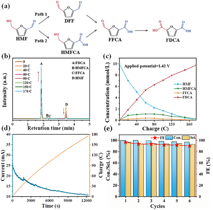
The electrocatalytic oxidation of HMF was conducted at a constant potential. The oxidation product analysis was performed through high performance liquid chromatography (HPLC) to verify the reaction pathway, conversion rates, selectivity, and FE. The conversion of HMF to FDCA involves a six-electron transfer reaction, requiring approximately 174 C of charge to achieve complete conversion of 30 mL of 10 mmol/L HMF into FDCA. Two potential pathways for HMF conversion into FDCA are illustrated in Fig. 5a. The aldehyde and hydroxyl groups of HMF can be selectively oxidized to generate 5-hydroxymethyl-2-furancarboxylic acid (HMFCA) or 2, 5-diformylfuran (DFF). These intermediates undergo further oxidation to produce 2-formyl-5-furancarboxylic acid (FFCA), which ultimately forms FDCA [4,12]. Constant voltage electrolysis was performed at 1.42 V vs. RHE under slight magnetic stirring, and liquid samples collected at various charge consumptions during electrolysis underwent HPLC analysis to identify and quantify the products. The HMF peak intensity consistently declined with charge depletion (retention time of 3.46 min), while FDCA signal intensity (retention time of 1.86 min) progressively increased. Fig. 5b shows the detection of intermediate products HMFCA (2.24 min) and FFCA (2.36 min). Notably, no intermediate DFF, aside from HMFCA and FFCA, was detected during HMF oxidation, indicating that the oxidation of HMF using the NiFe LDH/NiFeS hybrid arrays followed path 2, and the aldehyde group of HMF is selectively oxidized into carboxyl group. Fig. 5c illustrates the changing concentrations of HMF and its oxidation products related with consumed charge during electrolysis. FDCA is identified as the principal product with yields of other intermediates kept below 10%, which is in line with calibration curves (Figs. S11–S15 in Supporting information). Upon theoretical consumption of 176 C after 205 min of electrolysis, nearly 100% HMF conversion and 98.5% FDCA selectivity were achieved, yielding an FE of 97.2% at potential of 1.42 V vs. RHE. Fig. 5d indicates continuous HMF consumption on the electrode surface during electrolysis, leading to decreased current density as well as increasing transferred charge. Additionally, to evaluating catalyst stability, a constant potential electrolysis test was conducted over six consecutive cycles by the NiFe LDH/NiFeS electrocatalyst. Fig. 5e demonstrates consistent excellent conversion of HMF, FDCA selectivity, and FE across all six cycles, demonstrating robust stability in HMF oxidation. The morphology of the used NiFe LDH/NiFeS hybrid array is also characterized (Figs. S16a and b in Supporting information). Apparently, the well-preserved nanosheet array structure is observed. The thickness increase of nanosheet can be attributed to possible formation of hydroxide [45]. TEM and HRTEM images of used NiFe LDH/NiFeS were shown in Figs. S16c and d (in Supporting information), further confirming the 2D heterostructure with ultrathin nanosheets. The lattice spacing of 0.20 and 0.24 nm are attributed to the (018) plane of NiFe LDH phase and the (400) plane of NiFeS phase, respectively. These results demonstrate well stability of NiFe LDH/NiFeS hybrid arrays. Hence, these results demonstrate that 2D hybrid NiFe LDH/NiFeS is a highly efficient and stable electrocatalyst in HMF oxidation, even compared to most of advanced transition metal-based catalysts (Table S1 in Supporting information).
The effect of the applied potential on the catalytic performance is also investigated (Fig. S17a in Supporting information). With a potential of 1.32 V vs. RHE, HMFCA is the main intermediate in the initial process, resulting in a relatively low selectivity for FDCA production. Upon consuming 165 C of charge, HMF achieves the highest conversion rate at 89.0%, yielding FDCA as the primary product with a selectivity of 62.9% and an FE of 60.8%. It is crucial to note that the transformation of HMF to FDCA is inhibited as the applied potential increases, which is attributed to the competitive OER. Fig. S17b (Supporting information) demonstrates that complete transformation of HMF to FDCA requires 200 C at 1.52 V vs. RHE, notably surpassing the 174 C, although FDCA selectivity reaches 94.2% and the associated FE decreases to 81.8%. These results underscore the significant variations for necessary charge for complete HMF oxidation into distinct products as well as the selectivity and FE at different applied potentials.
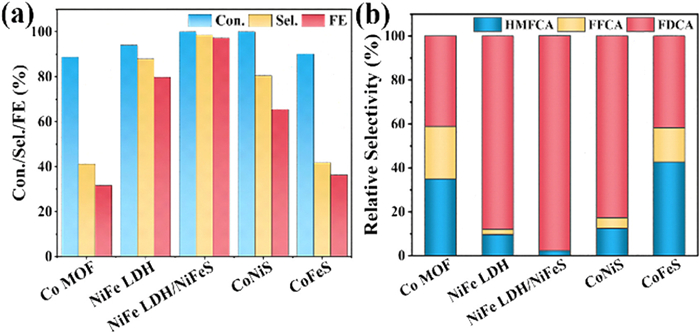
To investigate the influence of metallic composition on catalytic performance, two comparison samples (CoNiS and CoFeS) were also prepared through similar procedures. The XRD patterns of CoNiS and CoFeS are displayed in Fig. S18 (Supporting information). Fig. S19 (Supporting information) shows the comparison of the LSV curves for HMF electrocatalysis among these samples. Interestingly, CoNiS has a lower overpotential compared with CoFeS to achieve the same current density at a lower potential, while CoFeS requires a lower overpotential than CoNiS to achieve a higher current density. It is obvious that NiFe LDH/NiFeS has the lowest initial potential and the highest current density, which combines the advantages of each metal with the benefits of sulfidation, promoting oxidation reactions kinetics. Therefore, for the NiFe LDH/NiFeS catalyst, it is found that Ni promotes the reaction rate. The findings underpin that the formation of interface in NiFe LDH/NiFeS and synergistic catalytic effects of the bimetallic compounds can effectively promote the intrinsic activity. As shown in Fig. 6a, the conversion of HMF using catalysts containing Ni is almost 100% and the selectivity for FDCA is higher than other catalysts, while Co MOF and CoFeS exhibit the lowest selectivity for FDCA. Further analysis of oxidation products (Fig. 6b) show that a greater proportion of catalytic products remain as FDCA using NiFe LDH and NiFe LDH/NiFeS compared with other catalysts. These results indicate the main role of Ni sites for HMF oxidation, and the synergistic effect of Ni and Fe, which can enhance the selectivity of HMF conversion to FDCA.
To evaluate its industrial feasibility, the catalytic performance of NiFe LDH/NiFeS is further investigated by increasing the HMF substrate concentration (20, 30, 50 and 100 mmol/L). It is observed from Fig. 7a that the current density increases with the increase of HMF concentration at 1.42 V vs. RHE. It is noteworthy that when the concentration increases to 100 mmol/L, HMF reaches almost complete conversion and a promising selectivity to desired products with a Faraday efficiency exceeding 93% (Fig. 7b), suggesting its excellent potentials for industrial applications.

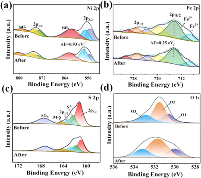
To investigate the correlation between the structure and activity of catalysts for HMF oxidation, the XPS was used to elucidate the state of active sites via comparison of pristine NiFe LDH/NiFeS and after cyclic tests. Fig. S20 (Supporting information) presents a comparison of full XPS spectra before and after electrocatalysis reactions, confirming the consistency of element composition. In the Ni 2p XPS spectrum of the used NiFe LDH/NiFeS catalyst (Fig. 8a), the Ni 2p peak shows a positive shift of 0.93 eV, accompanied by a substantial increase in the Ni3+peak resulting from the formation of NiOOH [46,47]. It has been reported that the higher valence state of Ni species (NiOOH) exhibits favorable adsorption structure/energy and enhances chemical interactions via electron transfer with HMF [48]. Similarly, the Fe 2p peak displays a positive shift of approximately 0.25 eV after cyclic electrolysis, implying possible electron transfer (Fig. 8b) [47]. Actually, it has been reported that the incorporation of Fe can influence the electronic structure of Ni(OH)2/NiOOH, making it highly active for OER or other small molecules [31,48,49]. Fig. 8c illustrates a lower intensity in the S 2p peak, implicating partial leaching of sulfur elements during oxidation, which possibly form SOx and are dissolved in the electrolyte. For the O 1s spectrum (Fig. 8d), wherein O1 (530.7 eV) correspond to metal-O and O2 (531.6 eV) correspond to metal-OH, while O3 (532.7 eV) indicates oxygen ions in low coordination or water physical and chemical adsorption on the surface. The metal-O bond peak decreases and the metal-OH bond peak increases significantly after electrocatalysis, indicating formation of metal hydroxides via the transformation of metal-oxygen bonds. The Ni 2p spectra further suggest a positive shift due to higher Ni valence states and oxyhydroxide formation, which are crucial in the electrocatalytic oxidation of HMF. Hence, it is reasonable to deduce that Ni3+ serves as the dominant active site, and Fe modulates the electronic configuration of Ni via partial charge transfer at the interface of NiFe LDH/NiFeS, and therefore facilitates the oxidation of HMF.
In summary, we developed 2D electrocatalyst consisting of NiFe LDH/NiFeS hybrid arrays via in-situ growth of bimetallic LDH and surface sulfidation towards HMF oxidation. The advantages of this electrocatalyst allowed for complete HMF conversion with about 98.5% yield and 97.2% FE for FDCA at 1.42 V vs. RHE, as well as superior stability retaining 90.1% FE for FDCA after six successive cycles. Moreover, at a high HMF concentration of 100 mmol/L, the electrocatalyst exhibited 83.6% yield and 93.6% FE for FDCA, demonstrating great promise for industrial applications. The enhancement of electrocatalytic performance can be attributed to high intrinsic activity, resulting from electron modulation at interfaces, and synergistic effect of Ni and Fe in NiFe LDH/NiFeS. Furthermore, the 2D layered open structure with ultrathin nanosheets is beneficial to increase the electrochemical surface area and lower the resistance of charge transfer, which can further improve the electrochemical properties and electrooxidation performance. Our present study demonstrates a strategy for the rational design and synthesis of efficient electrocatalysts via construction of 2D heterostructures and modulation of compositions, which offers valuable insights into effectively converting biomass into high-value products and chemicals.
The authors declare that they have no known competing financial interests or personal relationships that could have appeared to influence the work reported in this paper.
Lili Wang: Writing – review & editing, Writing – original draft. Ya Yan: Methodology, Formal analysis, Data curation. Rulin Li: Methodology, Formal analysis, Data curation. Xujie Han: Methodology, Formal analysis. Jiahui Li: Methodology, Conceptualization. Ting Ran: Methodology. Jialu Li: Methodology. Baichuan Xiong: Methodology. Xiaorong Song: Methodology. Zhaohui Yin: Methodology. Hong Wang: Methodology. Qingjun Zhu: Writing – original draft. Bowen Cheng: Conceptualization. Zhen Yin: Writing – review & editing, Writing – original draft, Conceptualization.
This work was supported by the National Natural Science Foundation of China (Nos. 51908408, 21872104) and Natural Science Foundation of Tianjin for Distinguished Young Scholar, China (No. 20JCJQJC00150).
Supplementary material associated with this article can be found, in the online version, at doi:
P.J. Deuss, K. Barta, J.G. de Vries, Catal. Sci. Technol. 4 (2014) 1174–1196. doi: 10.1039/C3CY01058A
M. Sajid, X. Zhao, D. Liu, Green Chem. 20 (2018) 5427–5453. doi: 10.1039/c8gc02680g
J. Li, L. Liu, Y. Liu, et al., Energy Environ. Sci. 7 (2014) 393–398. doi: 10.1039/C3EE41945B
X. Kong, Y. Zhu, Z. Fang, et al., Green Chem. 20 (2018) 3657–3682. doi: 10.1039/c8gc00234g
R.J. van Putten, J.C. van der Waal, E de Jong, et al., Chem. Rev. 113 (2013) 1499–1597. doi: 10.1021/cr300182k
Z. Zhang, K. Deng, ACS Catal. 5 (2015) 6529–6544. doi: 10.1021/acscatal.5b01491
K.R. Hwang, W. Jeon, S.Y. Lee, et al., Chem. Eng. J. 390 (2020) 124636. doi: 10.1016/j.cej.2020.124636
Y. Wang, K. Yu, D. Lei, et al., ACS Sustain. Chem. Eng. 4 (2016) 4752–4761. doi: 10.1021/acssuschemeng.6b00965
F. Liguori, P. Barbaro, N. Calisi, ChemSusChem 12 (2019) 2558–2563. doi: 10.1002/cssc.201900833
M. Kim, Y. Su, A. Fukuoka, et al., Angew. Chem. Int. Ed. 57 (2018) 8235–8239. doi: 10.1002/anie.201805457
D.K. Mishra, H.J. Lee, J. Kim, et al., Green Chem. 19 (2017) 1619–1623. doi: 10.1039/C7GC00027H
Y. Zhao, M. Cai, J. Xian, et al., J. Mater. Chem. A 9 (2021) 20164–20183. doi: 10.1039/d1ta04981j
B. Zhou, Y. Li, Y. Zou, et al., Angew. Chem. Int. Ed. 60 (2021) 22908–22914. doi: 10.1002/anie.202109211
L. Guo, X. Zhang, L. Gan, et al., Adv. Sci. 10 (2023) 2205540. doi: 10.1002/advs.202205540
S. Li, X. Sun, Z. Yao, et al., Adv. Funct. Mater. 29 (2019) 1904780. doi: 10.1002/adfm.201904780
G. Liu, T. Nie, Z. Song, et al., Angew. Chem. Int. Ed. 62 (2023) 202311696. doi: 10.1002/anie.202311696
Y. Yang, B. He, H. Ma, et al., Acta Phys. Chim. Sin. 38 (2022) 2201050. doi: 10.3866/pku.whxb202201050
M. Park, M. Gu, B.S. Kim, ACS Nano 14 (2020) 6812–6822. doi: 10.1021/acsnano.0c00581
J. Wang, X. Zhang, G. Wang, et al., Chem. Commun. 56 (2020) 13611–13614. doi: 10.1039/d0cc06087a
Z. Yin, M. Chi, Q. Zhu, et al., J. Mater. Chem. A 1 (2013) 9157. doi: 10.1039/c3ta11592e
K. Wang, J. Wu, S. Zheng, et al., Chin. J. Struct. Chem. 42 (2023) 100104. doi: 10.1016/j.cjsc.2023.100104
S. Zheng, J. Wu, K. Wang, et al., Acta Phys. Chim. Sin. 39 (2023) 2301032. doi: 10.3866/pku.whxb202301032
Q. Wang, D. O'Hare, Chem. Rev. 112 (2012) 4124–4155. doi: 10.1021/cr200434v
Y. Liu, Y. Wang, B. Liu, et al., Acta Phys. Chim. Sin. 39 (2023) 2205028.
Y. Wang, M. Zhang, Y. Liu, et al., Adv. Sci. 10 (2023) 2207519. doi: 10.1002/advs.202207519
J. Li, L. Wang, H. He, et al., Nano Res. 15 (2022) 4986–4995. doi: 10.1007/s12274-022-4144-6
C. Duan, L. Wang, J. Liu, et al., ChemElectroChem 8 (2021) 2272–2281. doi: 10.1002/celc.202100343
Y. Wang, D. Yan, S. El Hankar, et al., Adv. Sci. 5 (2018) 1800064. doi: 10.1002/advs.201800064
L. Wang, Y. Yang, B. Wang, et al., J. Alloys Compd. 885 (2021) 160899. doi: 10.1016/j.jallcom.2021.160899
Y. Wang, Y. Zhang, Z. Liu, et al., Angew. Chem. Int. Ed. 56 (2017) 5867–5871. doi: 10.1002/anie.201701477
M. Zhang, Y. Liu, B. Liu, et al., ACS Catal. 10 (2020) 5179–5189. doi: 10.1021/acscatal.0c00007
Y. Qi, K. Wang, Y. Sun, et al., ACS Sustain. Chem. Eng. 10 (2021) 645–654.
L. Yu, H. Zhou, J. Sun, et al., J. Mater. Chem. A 6 (2018) 13619–13623. doi: 10.1039/c8ta02967a
C. Kuai, Y. Zhang, D. Wu, et al., ACS Catal. 9 (2019) 6027–6032. doi: 10.1021/acscatal.9b01935
Y. Feng, K. Yang, R.L. Smith, et al., J. Mater. Chem. A 11 (2023) 6375–6383. doi: 10.1039/d2ta09426f
Z. Zhao, T. Guo, X. Luo, et al., Catal. Sci. Technol. 12 (2022) 3817–3825. doi: 10.1039/d2cy00281g
T. Wu, Z. Xu, X. Wang, et al., Appl. Catal. B: Environ. 323 (2023) 122126. doi: 10.1016/j.apcatb.2022.122126
Y. Zhong, R. Ren, J. Wang, et al., Catal. Sci. Technol. 12 (2022) 201–211. doi: 10.1039/d1cy01816g
X. Deng, X. Kang, M. Li, et al., J. Mater. Chem. A 8 (2020) 1138–1146. doi: 10.1039/c9ta06917h
L. Tan, J. Yu, C. Wang, et al., Adv. Funct. Mater. 32 (2022) 2200951. doi: 10.1002/adfm.202200951
X. Han, X. Wu, C. Zhong, et al., Nano Energy 31 (2017) 541–550. doi: 10.1016/j.nanoen.2016.12.008
Y. Tian, L. Xu, D. Yuan, et al., Nano-Micro Lett. 13 (2021) 3. doi: 10.1002/cam4.3590
Y.J. Lee, S.K. Park, Small 18 (2022) 2200586. doi: 10.1002/smll.202200586
J. Zhao, Y. Wang, Y. Qian, et al., Adv. Funct. Mater. 33 (2023) 2210238. doi: 10.1002/adfm.202210238
Y. Pei, L. Huang, L. Han, et al., Green Energy Environ. 7 (2022) 467–476. doi: 10.1016/j.gee.2020.10.019
X. Bai, W. He, X. Lu, et al., J. Mater. Chem. A 9 (2021) 14270–14275. doi: 10.1039/d1ta02464g
Q. Qian, Y. Li, Y. Liu, et al., Adv. Mater. 31 (2019) 1901139. doi: 10.1002/adma.201901139
X. Lu, K.H. Wu, B. Zhang, et al., Angew. Chem. Int. Ed. 133 (2021) 14528– 14535. doi: 10.1002/anie.202102359
P. Babar, A. Lokhande, V. Karade, et al., J. Colloid Interface Sci. 557 (2019) 10–17. doi: 10.1016/j.jcis.2019.09.012

Figure 1 Schematic illustration of the preparation process of NiFe LDH/NiFeS hybrid arrays.

Figure 2 Morphology characterizations of NiFe LDH/NiFeS hybrid arrays. (a–c) SEM with different magnifications, (d) TEM image, (e, f) HRTEM, (g) SAED, (h) STEM image and the corresponding EDS elemental mapping spectra.

Figure 3 High-resolution XPS spectra of (a) Ni 2p, (b) Fe 2p, (c) S 2p and (d) O 1s for NiFe LDH and NiFe LDH/NiFeS.

Figure 4 (a) LSV curves in 1 mol/L KOH with and without 10 mmol/L HMF of NiFe LDH/NiFeS, (b) LSV curves, (c) Tafel slopes, (d) Nyquist plots of Co MOF, NiFe LDH and NiFe LDH/NiFeS in 1 mol/L KOH with 10 mmol/L HMF.

Figure 5 (a) Two potential reaction pathways for HMF oxidation. (b) HPLC chromatograms at different charge states during the electrolysis experiment. (c) Concentration versus passed charge plot of HMF, FDCA, and the intermediates during the electrocatalytic oxidation of HMF. (d) Current-time and charge-time transients during constant potential electrolysis of NiFe LDH/NiFeS at 1.42 V vs. RHE in 1 mol/L KOH with 10 mmol/L HMF. (e) Conversion, selectivity and FE for FDCA of NiFe LDH/NiFeS after six cycles.

Figure 6 (a) Conversion of HMF, selectivity and FE of FDCA. (b) Relative selectivity of different products obtained by different electrodes tested in 1 mol/L KOH with 10 mmol/L HMF at 1.42 V vs. RHE.

Figure 7 (a) Current density for HMF oxidation of different concentrations at 1.42 V vs. RHE by NiFe LDH/NiFeS. (b) Conversion of HMF and FDCA selectivity/FE by NiFe LDH/NiFeS at different HMF concentrations.

 扫一扫看文章

扫一扫关注我们
 DownLoad:
 下载:
下载:

 下载:
下载: