
Figure 1.
Schematic illustration of materials, mechanisms and applications of the PEDOT-based TE composites.
PEDOT-based thermoelectric composites: Preparation, mechanism and applications
Jia Fu , Shilong Zhang , Lirong Liang , Chunyu Du , Zhenqiang Ye , Guangming Chen

Nowadays, unsustainable resources such as conventional fossil fuel-based energy technologies inevitably bring environmental problems, which gradually aggravate the energy crisis, and even induce economic problems and regional conflicts. Sustainable thermoelectric (TE) energy materials and corresponding devices bring a new development direction [1]. The mechanism of TE conversion is based on the mobility deviance of internal charge carriers when exposed to temperature gradients. Due to its capability to harvest waste or low‐grade heat for usable electrical energy, TE technology has become a promising method for power energy collecting, thereby attracting significant attention in recent decades [1,2]. The performance of TE materials is generally evaluated by a dimensionless figure of merit (ZT), defined as ZT = S2σT/κ, where S, σ, T, and κ stand for the thermopower or Seebeck coefficient, the electrical conductivity, the absolute temperature, and thermal conductivity, respectively. Accordingly, a large S, high σ, and low κ are desirable for high TE performance. Unfortunately, decoupling these three parameters is always difficult due to their strong interdependence, making it challenging to achieve significantly enhanced TE performance [3]. For most organic or organic/inorganic composites, the power factor (PF) is usually applied instead of ZT, defined as PF = S2σ. This is mainly due to the low thermal conductivities of these systems and the difficulty in precisely measuring the in-plane thermal conductivities of thin films.
Since the discovery of the Seebeck effect in 1821, inorganic TE materials have been extensively studied, including Bi2Te3, PbTe, Sb2Te3, PbSe, PbS and their alloy systems [4]. However, their inherent rigidity and brittleness, poor processability, toxicity and low abundance in the earth hinder their practical applications. Hence, the search for new materials to address these issues is urgent and of high importance. In recent decades, organic TE materials (i.e., organic small molecules, organic conducting or conjugated polymers, and organic/inorganic composite materials) have achieved significant advancements, possibly due to their distinct advantages such as intrinsic flexibility, low thermal conductivities, elemental abundance (C, O, H, N and S) and excellent processability compared with their inorganic counterparts. Various conducting polymers, such as poly(3,4-ethylenedioxythiophene) (PEDOT), polyaniline (PANI), polythiophene (PTh), polypyrrole (PPy), polyacetylene (PA), polycarbazole (PC) and their derivatives, have been employed in the organic and composite TE studies. Indeed, research on TE composites of conducting polymers with inorganic nanoparticles has made significant progress, for instance, PEDOT/carbon nanotube (CNT), PANI/CNT, PPy/CNT composites [1-4].
Among the organic and organic/inorganic composites reported so far, PEDOT is perhaps the most widely investigated and most successful type of polymer material. PEDOT displays high electrical conductivity, low thermal conductivity, good environmental stability, and metallic and semi-metallic performance [5]. PEDOT: poly(styrene sulfonate) (PEDOT: PSS) is a mature commercial product that has greatly expanded the range of applications in diverse organic electronic fields, including TEs [6], light emitting diodes [7-11], field effect transistors [12-14], solar cells [15-18], supercapacitors [19,20], sensors [21], and electrochromic devices [22-24]. PEDOT itself is insoluble in water and most common solvents, the introduction of PSS enables PEDOT solvation and solves the processability problem. Unfortunately, the presence of an excess amount of the electrical insulative PSS greatly reduces the conductivity of PEDOT. Nevertheless, the TE performance can be conveniently adjusted by doping and dedoping, nanostructure fabrication, and compositing with different inorganic nanoparticles [25-28, [29]. For instance, by doping or controlling the proportion of PSS in PEDOT: PSS, the conductivity of PEDOT: PSS can vary from 10−6 S/cm to 103 S/cm [30,31]. In addition, to significantly enhance the TE properties, many PEDOT-based composites have been successfully prepared by dispersing different inorganic nanoparticles, such as Bi2Te3 [32], CNTs [33], Te nanowires [34], Ca3Co4O9 [35], PbTe [36], Au [37], Ge [38], and organic materials [39].
Here, we focus on the recent developments of PEDOT-based TE composites. Although there have been some reviews on TE composites and their devices, the rapid development of this field has aroused the demand for a timely summarization of the recent research advances in PEDOT-based TE composites. Here, we systematically summarize the progress of this topic following the sequence of preparation, mechanisms and applications (Fig. 1). First, we introduce the preparation of PEDOT-based TE composites, discussing films, hydrogels/aerogels, and fibers/yarns, and then highlighting the enhanced TE performances achieved. Then, we elucidate the inherent mechanism of the structure-TE property relationship, which includes doping-dedoping, interfacial energy-filtering, and polymer aggregation structure adjustment. Next, we focus on the device fabrication and applications, specifically power generation and sensing. Finally, we provide an outlook on the prospects and challenges of PEDOT-based TE composites.
TE materials can be classified into three forms: thin films, hydrogels/aerogels, and fibers/yarns, each with its own specific application scenarios. Next, we will summarize the typical fabrication methods for these different forms of TE materials.
TE films are currently the most widely studied and extensively applied form of TE materials. TE films not only exhibit excellent adaptability and flexibility but also improve the contact between the material and electrodes or substrates, which helps to enhance TE performance and to facilitate efficient thermal energy conversion and transfer.
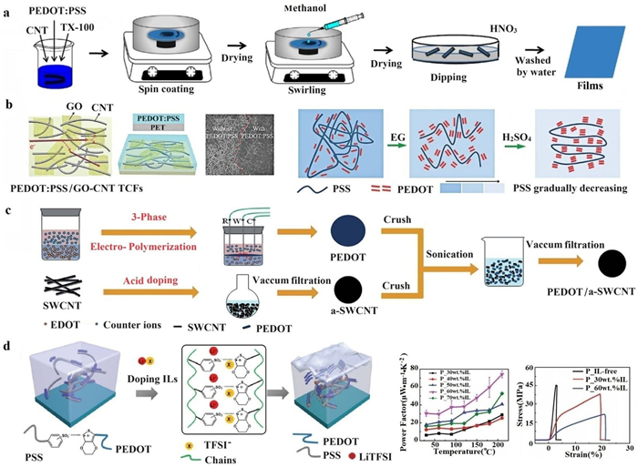
Fig. 2 illustrates the typical preparation methods for PEDOT films, primarily including spin-coating, vacuum filtration, drop coating, and vapor deposition. Geng et al. [40] employed a spin-coating process to produce CNT/PEDOT: PSS films, as depicted in Fig. 2a. In this process, PEDOT: PSS served to lower the film's sheet resistance and CNTs facilitated stability and prolonged the device lifetime. Moreover, they applied methanol and nitric acid as post-processing to further enhance electrical resistance, substrate adhesion, and film roughness. Various coating layers and corresponding treatment methods have also been used to improve the electrical conductivity of films. Researchers have employed PEDOT: PSS to enhance the graphene oxide (GO)-CNT network [41], discovering that PEDOT: PSS can permeate the network's pores and densify the GO—CNT networks, as depicted in Fig. 2b. Chen et al. [42] employed dynamic three-phase interfacial electro-polymerization and chemical doping to produce PEDOT/a-SWCNT films, as illustrated in Fig. 2c. This process significantly enhances electrical conductivity while reducing the Seebeck coefficient, with a maximum PF of 350.0 ± 47.6 µW m−1 K−2. Liu et al. [43] utilized the modulation effect of bis(trifluoromethane)-sulfonimide lithium salt (LiTFSI), an ionic liquid, to synergistically enhance both the TE and mechanical properties of PEDOT films. The electrical properties of LiTFSI/PEDOT: PSS composite flexible organic TE thin films, as shown in Fig. 2d, improved nearly two orders of magnitude compared to untreated PEDOT: PSS thin films. The composite film exhibited a PF of 75 µW m−1 K−2 and a tensile strain exceeding 20%.
In summary, PEDOT-based films exhibit enhanced TE properties. Optimizing their performance via thermal treatment requires balancing between electrical conductivity and the Seebeck coefficient. Acidic doping and adjusting material ratios effectively regulate TE performance. Furthermore, pre-treatment, filler incorporation, post-treatment, and the addition of ionic liquids can also enhance interactions between conductive polymer chains. In addition, these interactions lead to the formation of a cross-linked structure, thereby enhancing the mechanical properties of the films.
For the preparation of PEDOT aerogel, a common approach is through the sol-gel process, including mixing and freeze-drying. Chen et al. reported an elastic PEDOT-tosylate (PEDOT-Tos)/SWCNT aerogel fabricated via convenient chemical oxidative polymerization, physical mixing and subsequent freeze-drying process [44]. PEDOT-Tos powder is obtained through oxidative polymerization with ammonium peroxydisulfate (APS) and para-toluene sulfonic acid (pTSA), followed by the preparation of PEDOT-Tos and SWCNT dispersion through sonication, and their subsequent mixing, as depicted in Fig. 3a. Organic TE aerogels possess low thermal conductivity, excellent flexibility, and versatility [44,45]. The thermal conductivity of a compressed porous aerogel composed of PEDOT: PSS, which includes a 5% volume concentration of N-methyl-2-pyrrolidone (NMP), has been measured to be 0.10 W m−1 K−1, as indicated in [45].

PEDOT hydrogels can be prepared using the acid treatment method[45], freeze-thaw (FT) method [46], chemical crosslinking method [47] and photo-induced gelation method [48]. The concentrated sulfuric acid treatment can partially remove the PSS in PEDOT: PSS solution. It is reported that the PEDOT hydrogel has a high conductivity of 880 S/m with a low solid content of 4 wt% after concentrated sulfuric acid treatment [45]. As depicted in Fig. 3b, the hydrogel can be fabricated into different shapes such as films, fibers, and columns with arbitrary sizes for diverse needs. Chen et al. employed a convenient FT induced gelation and subsequent high-speed wet-spinning process to fabricate PEDOT TE generator [46]. The spinnability and TE properties were obviously improved by regulating the FT cycles, as shown in Fig. 3c. Zhao et al. fabricated pure PEDOT: PSS hydrogels with excellent performance by designing interconnected networks of PEDOT: PSS nanofibrils [47]. According to Fig. 3d, the method involves mixing volatile additive dimethyl sulfoxide (DMSO) into aqueous PEDOT: PSS solutions followed by controlled dry-annealing and rehydration. Their hydrogels exhibited high electrical conductivity, high stretchability, low Young's modulus, superior stability, and tunable isotropic/anisotropic swelling in wet physiological environments. Zhang et al. reported a three-dimensionally (3D) printable conductive hydrogel with high electrical conductivity, which can be photocrosslinked [48]. The conductive printing solutions composed of polyethylene glycol diacrylate, PEDOT: PSS and photoinitiator were placed on the Z-controlled movable container and printed by UV laser exposure.
In general, the differences between aerogels and hydrogels lie in their preparation processes and drying methods. For PEDOT aerogel, the preparation process relies on the sol-gel process and supercritical drying or freeze-drying. On the other hand, the preparation of PEDOT hydrogel typically involves concentrated acid treatment and FT method. These distinct preparation methods result in structural and property differences between aerogels and hydrogels, making them suitable for different applications and requirements.
PEDOT fibers and yarns are typically soft and flexible, allowing them to adapt to various shapes and curved surfaces, which can be woven, knitted, braided, or formed into different structures and shapes to meet specific requirements of wearable devices, providing a comfortable feel when in contact with the human body or objects.
The wet-spinning method is the most suitable method for preparing PEDOT fibers, owing to advantages like good solubility of PEDOT, excellent fiber-forming capability, the ability to create ordered structures, and scalability. The preparation process of wet-spinning includes the preparation of the PEDOT: PSS solution, spinning into fibers, solidification in coagulation bath, and possible subsequent treatments, such as acid treatment, drawing or stretching treatment. Fig. 4 depicts the typical processes of the preparation of PEDOT: PSS fiber and yarn. Ruben et al. [49] investigated the drawing effect on the properties of PEDOT: PSS fibers. They incorporated a DMSO draw bath following the initial coagulation process, as shown in Fig. 4a. Drawing induces a preferential orientation of PEDOT chains in the fiber-axis direction, enhancing the mechanical properties and electrical conductivity [50]. Pan et al. [51] produced PEDOT fibers via a continuous wet-spinning process, followed by a one-step sulfuric acid treatment, as shown in Fig. 4b. The acid treatment enhanced the electrical conductivity of the PEDOT fibers. The advantages of PEDOT: PSS fibers include their feasibility of large-scale production, excellent electrical conductivity, and adaptability to various shapes. However, these fibers also have some disadvantages. These include susceptibility to variations in raw material quality, potential requirements for specific solvents and process controls, and the comparatively lower conductivity, which necessitates engineering optimization [52,53].

Besides fiber, yarn represents another typical fabric type. The preparation of PEDOT yarn differs from the fiber. The latter is made originally from the PEDOT solution, while PEDOT yarn is typically fabricated by coating, dyeing, or printing PEDOT onto basic textiles. As depicted in Fig. 4c, Zhang et al. [54] fabricated PEDOT: PSS/CNT yarn (CNTY) by immersing the CNTY in a PEDOT: PSS bath. A p-n segment design was employed in fabricating CNT-based TE yarns (TEYs), formed by alternately dipping the yarns into PEDOT: PSS (p-type) and PEI (n-type) solutions [54]. This p-n segment design significantly reduced the electrical contact resistance and enhanced the mechanical properties, leading to outstanding TE conversion efficiency in TEYs. The key to this design lies in the alternating arrangement of p-type and n-type TE materials, significantly improving the overall TE performance of thermoelectric textiles (TETs), exhibiting a power density of up to 51.5 mW/m2 and a voltage density of 520.9 V/m2 at a temperature difference of 47.5 K. This design not only enhances TE conversion efficiency but also maintains the flexibility and wearability. This fabrication method facilitates large-scale production of TE textiles.
The PEDOT: PSS, CNTs and other organic TE materials offer advantages such as good flexibility, low thermal conductivity, and the capability for large area processing [55], making organic TEGs attractive for commercial applications. A series of methods have been explored to enhance the TE performance of PEDOT: PSS, including pre-treatment, filler addition, post-treatment, and manipulation of defects [56-59]. Additionally, special computing methods like the asymmetrical transport distribution function [60] and machine learning [61] have been proposed for analyzing TE performance. Regulation mechanisms mainly focus on three types of TE composites based on PEDOT: PSS: doped and dedoped nanoparticle structures, network structures and polymerization structures.
Doping PEDOT involves introducing additional charge carriers containing various molecules or ions, increasing the carrier concentration in PEDOT and altering its energy band structure. The charge transport properties have been enhanced, and the electrical conductivities of the doped TE composites are significantly enhanced. Conversely, dedoping refers to removing dopant molecules or ions from PEDOT, changing it back toward its initial undoped state. The dedoped treatment of the PEDOT macromolecule leads to a decrease of carrier concentration, and thereby reduces the electrical conductivity and lowers the charge transport properties. Next, we will review the influence of doping/dedoping on the conjugated chains and degree of crystallinity of PEDOT molecules.
Caironi et al. [62] revealed the morphological, compositional, and energetic evolution of PEDOT: PSS with the addition of the secondary dopant, DMSO. They observed the system's evolution after secondary doping with AFM and grazing incident wide angle X-ray scattering (GIWAXS), and detected the compositional structure using X-ray photoelectron spectroscopy (XPS). They found that the compositional changes do not influence the molecular packing and the thin film crystallinity. Ouyang et al. [63]. reported TiO2-doped PEDOT TE materials with a high Seebeck coefficient and high conductivity, of which the Seebeck coefficient can be enhanced via UV light exposure. The mechanism of this enhancement in Seebeck coefficient is that UV light induces electrons to be excited from the valence band to the conduction band in TiO2 particles, resulting in the subsequent electron transfer from the conduction band of TiO2 into PEDOT: PSS. Doping and dedoping processes, when executed sequentially, have a synergistic effect on enhancement. Kim et al. reported a simple chemical dedoping treatment of PEDOT: PSS nanofilms to enhance the TE properties of the polymer nanofilms [64], achieved by over-coating with a mixture of DMSO and hydrazine, as shown in Fig. 5a. An optimized power factor of 112 µW m−1 K−2 is obtained with 0.0175 wt% hydrazine in DMSO at room temperature. Fig. 5b shows the preparation process of a flexible PEDOT film proposed by Chen et al. [65]. They employed a combination of DMSO doping and NaBH4 dedoping strategies to enhance the TE properties of flexible PEDOT films. They found that the reduction of the oxidation level of PEDOT: PSS after NaBH4 dedoping led to a balance between conductivity and the Seebeck coefficient.
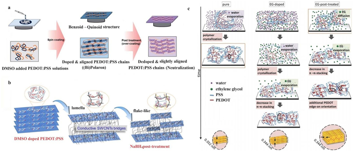
There have been numerous studies on the underlying mechanism of doping and dedoping. The microstructures of conjugated polymers span multiple scales, from crystalline/amorphous microstructures at microscale to molecular structures at nanoscale. The π interactions of conjugated polymers, encompassing long-range order and site-specific π contacts, are denoted as π-stacking [66]. It has been shown that higher carrier mobility is typically associated with greater crystallinity and reduced disorder in polymer films [67]. The π-interactions formed between polymer chains in solution-state aggregates can transfer to the solid-state microstructures [68]. Precise control of the solution-state aggregation of conjugated polymers can lead to finely tuned solid-state microstructures and enhanced charge transport properties [66]. The crystallization process is slowed down, resulting in better stacked chains when ethylene glycol (EG) is added to the PEDOT: PSS [69,70], compared to the pure material shown in Fig. 5c. The degree of crystallinity of PEDOT: PSS thin films is substantially increased by the corresponding post-treatment methods [68]. When the thin films are further treated with an EG bath, the system recrystallizes and shifts from a face-on to an edge-on configuration.
The network structure of PEDOT: PSS-based composites is often intentionally designed to achieve a stretchable, compressible, and wearable TE generator that can efficiently harvest heat. One approach to achieving this is through hierarchical hybridization, which involves introducing two or more effective dopants, such as CNT, reduced graphene oxide (rGO), and fullerene (C60), into PEDOT-based systems [71].
The blended dispersion of long CNTs and PEDOT: PSS can achieve a well-cross-linked network structure. Functionalized PEDOT: PSS nanoparticles cover the surface of CNT and connect with each other through long CNTs to form a network structure [72-74], significantly improving electrical conductivity and mechanical properties. The presence of the CNT/PEDOT: PSS interface gives rise to the exceptional TE transport properties, which can impede phonon transport but promote electron transport. The interconnecting nodes between CNTs, designed by Chen et al. [75], achieve a limitation on phonon transmission while maintaining high electrical conductivity. In this design, the CNTs are covered by PEDOT through native polymerization, as shown in Fig. 6a. After post-treatment with the ionic liquid LiTFSI, the electrical conductivity of the composite improved by almost 46%, meanwhile, the Seebeck coefficient remained nearly constant.

Fig. 6b depicts the CNT network structure, energy-filtering effect, and the three regions categorized by the main carrier transport mechanism and TE properties of PEDOT: PSS/CNT composite films. The CNT network structure is composed of primary particles and aggregates, with blue and green arrows pointing to the primary particles and aggregates, respectively. The energy-filtering effect was induced by primary particle/aggregate interfaces, where the high-energy carriers can pass across the energy barrier and the low-energy ones are filtered. The main carrier transport regions were divided into three regions [76]: percolation-like effect region (Region I), energy-filtering effect region (Region II) and equilibrium region (Region III). Consequently, the curve of electrical conductivity with SWCNT loading reveals an S-shaped behavior in Region I.
Similarly, the intercalated composites of reduced graphene oxide/reduced PEDOT: PSS (rGO/rPEDOT: PSS) reported by Chen et al. [77] achieved a stable network structure. The flexible rGO/rPEDOT: PSS composite films shown in Fig. 6c were prepared by vacuum filtration, where PEDOT: PSS was intercalated into the GO nanolayers, and both GO and PEDOT: PSS were simultaneously reduced to rGO and rPEDOT: PSS, respectively, by hydriodic acid. Due to the high electron mobility in graphene, the carrier mobility between graphene and PEDOT: PSS is enhanced, resulting in a significant improvement in electrical conductivity. This synergistic effect, characterized by the simultaneous improvement in electrical conductivity and Seebeck coefficient along with reduced thermal conductivity, results in the highest power factor of 107.5 ± 5.5 µW m−1 K−2. Composites combining one-dimensional and two-dimensional materials can exhibit synergistic enhancement effects. Yin et al. prepared rGO/CNT/PEDOT: PSS (GCP) ternary composites [78]. The strong π-π interaction between rGO/CNTs and PEDOT: PSS leads to the formation of ordered regions. The porous structures of the rGO/CNTs aerogel act as a conductive network skeleton, promoting carrier transport in GCP composites.
Generally speaking, the construction and evolution of the network structure in PEDOT: PSS-based composites can be described as follows: First, the insulating PSS component is replaced by conductive carbon materials, creating a bridge among the PEDOT-rich chains within the composite film. This substitution not only enhances the overall conductivity of the film but also allows for more efficient charge transport, further improving the electrical conductivity of the hybrid films. Additionally, conductive PEDOT: PSS materials are strategically positioned between the graphene and CNT networks. This arrangement helps to reduce the contact resistance between the carbon materials, improving the electrical conductivity of the hybrid films. By optimizing the composition and arrangement of the components within the composite, the network structure evolves to facilitate enhanced electrical conductivity, making the material more suitable for TE applications.
The transition of polymer molecular and aggregation structures can significantly influence the TE performance. Firstly, the transition can induce template-directed polymerization. Xu et al. reported a PEDOT/rGO nanocomposite with a pie-like structure, featuring rGO nanosheets and PEDOT layers as cores and shells [79], as illustrated in Fig. 7a, where template-directed in situ polymerization occurred on the rGO surfaces. Through ultra-sonication and stirring, EDOT molecules were adsorbed onto the surfaces of 2D rGO nanosheets templates, owing to strong π-π interactions. Fig. 7b shows the nanocomposites consisting of PEDOT: PSS-coated multiwalled-CNTs (MWCNT) via template-directed in situ polymerization [80]. Owing to π-π attraction and van der Waals interactions, the EDOT monomers were closely adsorbed onto the surfaces of the MWCNT/PSS templates. Following the addition of ammonium peroxidisulfate and iron chloride (FeCl3), an in situ oxidized polymerization reaction of EDOT monomers occurred on the surfaces of the dispersed MWCNTs.
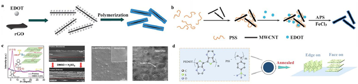
Secondly, enhanced crystallinity, resulting from the transition of structures, is another potential mechanism affecting TE performance. The structural transition of PEDOT monomers from benzoid to quinoid, following DMSO—H2SO4 double treatments, results in increased crystallinity. Chen et al. developed a new strategy to improve the interfacial resistance in TE materials [81]. As depicted in Fig. 7c, they employed highly crystallized PEDOT: PSS as the matrix, with fillers coated with a CuTe layer. This strategy improved the charge transport characteristics between the matrix and the filler. The smaller fillers, enveloped by PEDOT: PSS, can be attributed to the blocking effects of conductive polymers, beneficial for optimizing interfacial carrier transport. Consequently, this leads to optimized interfacial carrier transport with improved mobility, favorable for enhanced conductivity.
Thirdly, interchain coupling between polymer chains in PEDOT: PSS films significantly affects electronic transport. The transition to a more ordered structure, like edge-on stacking, enhances the intercoupling of macromolecular chains, thereby enabling efficient carrier hopping and transport. Fig. 7d shows a schematic illustration of the interchain coupling in the PEDOT: PSS film after the annealing and subsequent solvent post-treatment process [82]. The two π-π stacking orientations, edge-on and face-on, for crystalline PEDOT chains, are considered. The interchain coupling significantly impacts the electronic transport in PEDOT: PSS films. The predominantly preferred π-π edge-on stacking orientation dramatically facilitates carrier hopping and transport along the in-plane direction, superior to face-on stacking in thin films, thus favoring carrier hopping and transport in intercoupled macromolecular chains.
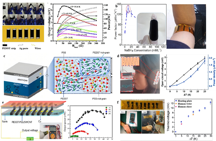
TE power generation devices can be classified into TE generators (TEGs) and thermoelectric cells (TECs), based on their operating principles. TEGs generate electricity through the migration of charge carriers, whereas TECs produce current based on chemical redox reactions. These devices can be designed in a wearable form to collect waste heat from the human body. Such devices generate electricity by utilizing the temperature difference present on the body [83-88]. Fig. 8a showcases a one-dimensional PEDOT TEG, prepared using a simple self-assembled micellar soft-template method and vacuum-assisted filtration [83]. The flexible TE prototype composed of six strips (7 mm × 30 mm) of the PEDOT nanowire films connected in series showed an output power of 157.2 nW at a temperature difference of 51.6 K. A flexible TE thin film device reported by Chen et al. [84] was made by using Sb2Te3 composite nanowire as the n-leg and Te-PEDOT: PSS as the p-leg, as shown in Fig. 8b. Worn on human arms, this device, when its external resistance equaled the resistance of the device, demonstrated an increase in voltage with increasing external resistance, ultimately achieving a peak output power density of approximately 1 µW/cm2. Paipetis et al. fabricated PEDOT: PSS TE fibers [85], which delivered a high electrical conductivity of 4029.5 S/cm with a Seebeck coefficient of 19.2 µV/K. Fig. 8c illustrates the mechanism of charge transfer in a PEDOT-based power generation device. The formation of PEDOT-rich and PSS-rich phases in the uniform mixture provides a pathway for charge transfer [86]. Fig. 8d depicts a fibrous TEG sewn onto ear muffs [51], consisting of five pairs of PEDOT: PSS-Ni TE couples connected to foam. The fibrous TE legs are arranged along the thickness direction of the foam. This configuration results in an open-circuit voltage of 0.72 mV when the temperature difference is 3.6 K. A variety of wearable devices have been designed, besides arms and ears, fingers [76], wrist, and chest can also be used as heat sources [81], as shown in Figs. 8e and f.
In addition, the harnessed heat can be utilized to provide a constant power source for other devices, such as charging dielectric capacitors, electrochemical supercapacitors, and green LEDs [89-92]. In the gel electro-decomposition process, PVA-FeCl2/3 transforms into PEDOT: PSS electrodes, effectively connected in a series of p-n batteries. This configuration allows for a high energy output (up to 38.3 µW) suitable for charging a dielectric capacitor (C = 10 mF), electrochemical supercapacitors (C = 470 mF), and powering a green LED [89]. This TE device design can also facilitate the creation of a direct thermal rechargeable battery [90] and thermosensitive crystalline liquid TECs [91]. Liu et al. designed a leaf-inspired flexible TEG [92], in which the TE thin films were designed in a vertical orientation to harness the environmental temperature difference and achieve a higher output power. With a 30 ℃ temperature difference, the 10-leaf-TEG obtained a maximum power of 0.38 µW per leaf.
In addition to waste heat recovery, thermoelectric devices can also be used as sensors. Flexible wearable physical sensors and personalized medical sensors represent important application scenarios for TE devices. These devices are commonly used in wearable applications such as health monitoring, medical treatment, and human body movement detection [93].
With their wide range of applications and growing popularity, wearable sensing devices have a promising market outlook. Fig. 9 illustrates the diverse potential applications of wearable TE devices in various sensing scenarios. Fig. 9a depicts the extraordinary market performance of TE wearable electronic devices, highlighting typical modules with high power generating efficiency and the estimated global market values of wearable electronics [94-96]. Fig. 9b illustrates a PEDOT: PSS/MXene composite aerogel, which has been used to assemble pressure sensors for wearable physical monitoring and high-resolution sensor microarrays for robotic tactile sensing [97]. The 3D network composed of MXene and PEDOT: PSS exhibits excellent mechanical flexibility and piezoresistive properties, resulting in high sensitivity and fast response capabilities. Wang et al. reported on a multi-layered structure comprising PEDOT nanowires, cellulose nanofibers (CNF) and PEDOT: PSS fabric, referred to as PPCF, as depicted in Fig. 9c. The sensor based on layered conductive fabrics boasts high sensitivity, a wide detection range, and excellent stability. The PPCF pressure sensor demonstrates significant potential for medical applications, particularly in real-time detection of human behavior and physiological signals. Once attached, the flexible pressure sensor can detect various states of finger movement, the frequency and intensity of human swallowing behaviors, and relative current changes due to muscle contractions in a clenched hand, which compress the sensor. Additionally, it can detect blood pressure changes due to left ventricle contractions and the reflective wave from the lower body. Chen et al. reported on PEDOT-based TE devices [77] capable of accurately recognizing gestures. Fig. 9d illustrates the working principle of these devices. Sensors placed on the knuckles generate voltage signals corresponding to different hand gestures involving fourteen knuckles. This feature enables the accurate recognition of hand gestures, including "Point, " "Pinch, " and "Grip". Similarly, TE devices can be integrated into clothing at the knee, functioning as a wearable body motion monitoring sensor to detect knee movements, thus enabling real-time monitoring of the physical state of the knee joint [98], as shown in Fig. 9e. Zhu et al. proposed a cost-efficient and scalable approach to create a highly flexible and compressible conductive sponge for piezoresistive pressure sensor [99], as demonstrated in Fig. 9f. With this sensor, a variety of human motions can be monitored, including speaking, finger bending, elbow bending, and walking. Senem et al. reported on an ink-jet-printed CNT/PEDOT: PSS temperature sensor with excellent temperature sensitivity [100]. This sensor can be directly deposited onto textiles. A sensitive temperature response curve can be obtained when a finger touches the printed sensors.

In addition to human body monitoring, TE power generation devices can also be used for environmental monitoring. Wang et al. developed a methanol gas sensor made from a blend of PEDOT: PSS and MXene, capable of sensitively monitoring methanol gas emissions [101].
Polymer and polymer-based composites are considered promising TE materials for TE devices. Thus far, the focus has been on PTh derivatives, including PEDOT, as p-type polymers, due to their high PF values, which can reach hundreds of µW m⁻¹ K⁻² at room temperature. To achieve high conductivity, specific features are required in PTh derivatives, such as high carrier mobility, a well-ordered structure, favorable surface morphology, and a high doping level. Consequently, the selection of polymers, effective dopants, and suitable doping processes becomes critical. The use of effective doping or dedoping agents for PEDOT: PSS, combined with refined treatment processes, is believed to hold the potential for groundbreaking developments in organic TE materials. However, the impact of polymer chemical structure or molecular organization on the Seebeck coefficient remains unclear. Therefore, the power factor of PEDOT: PSS still remains relatively low, necessitating the further exploration of the mechanism between structure and TE performance. The relationship between structure and TE properties, as well as the field of doping engineering, should be investigated further in the future.
Significant progress has been achieved in the ongoing research. Researchers are investigating the use of specific doping agents and dedoping techniques for PEDOT: PSS composites to regulate TE properties. By refining treatment processes and exploring doping engineering, breakthroughs in organic TE materials are expected. It is believed that the ZT value of TE polymers may eventually match or even surpass that of the best inorganic TE materials. This prospect opens up exciting possibilities for the development of flexible TE systems. These versatile TE systems offer valuable applications in areas such as harnessing low-grade heat and empowering wearable electronic devices. The application of PEDOT TE thin films in the fields of low-grade energy harvesting and wearable devices holds great potential and promising prospects. Current research has started to explore the utilization of PEDOT TE thin films in these areas and has made some progress. In the future, with a deeper understanding of the performance characteristics of PEDOT TE thin films and further technological advancements, their application in low-grade energy harvesting and wearable devices shows a broad range of possibilities. These applications contribute to improving energy utilization efficiency, driving the development of wearable technologies, and providing new solutions in the fields of sustainable energy and smart electronic devices.
Future work on PEDOT: PSS-based composites will involve achieving a balance in their TE properties by improving the crystallinity of PEDOT chains, controlling the PEDOT to PSS ratio during synthesis or secondary doping, and optimizing doping levels. Achieving a uniform filler distribution within PEDOT: PSS requires continuous efforts to enhance preparation processes, including surface modifications. Besides filler distribution, considering filler interface interactions and orientation will be essential in optimizing the TE properties in future research on PEDOT-based composites. Balancing electrical conductivity with stretchability and optimizing TE properties through improved filler distribution and interface interactions will continue to be challenges in the near future. These advancements highlight the ongoing efforts to enhance understanding and manipulation of charge transport and thermal properties in various materials, vital for developing more efficient electronic and TE devices.
The field of measuring thermal conductivity, carrier mobility, and concentration faces several challenges, especially in the context of charge transport in high-mobility polymers and semiconductors. Investigating temperature-dependent charge localization in high-mobility, solution-crystallized small molecule semiconductors and understanding the emergence of charge coherence in organic semiconductors are crucial. This requires mitigating thermal fluctuations and examining the impacts of molecular vibrations and strain on these materials. Understanding this is paramount for comprehending how thermal factors affect charge transport in these advanced materials. In the case of PEDOT-based composites, recent studies in thermal conductivity and carrier mobility/concentration have primarily focused on enhancing their TE performance. Within the realm of nanostructures, emphasis is placed on exploring how different nanoscale structures and band structures can influence carrier mobility in materials. This aspect is pivotal to the development of advanced TE materials and has the potential to substantially improve electronic devices and energy conversion technologies.
Regarding future trends in PEDOT-based composites, particularly in understanding their transport mechanisms, the focus is on optimizing properties such as electrical conductivity, stretchability, and TE performance through careful molecular or structural design. Enhancing or promoting charge carrier transport within these composite materials through strategic material design is key to understanding their transport mechanisms. Regarding fillers, appropriately sized ones, such as one-dimensional fillers (e.g., Te nanorods), can induce highly ordered PEDOT: PSS layers. In terms of structural design, constructing layered structures or encapsulating PEDOT: PSS at the nanoscale within an elastic matrix to form conductive pathways exploits unique thermodynamic properties arising from finite size and interface effects. In terms of strategies, achieving better phase morphologies in properties can be accomplished by finely controlling processing methods and interface interactions. On the theoretical front, the development of theories and models for organic TE materials to predict their electrical and thermal transport properties remains a significant challenge.
The authors declare that they have no known competing financial interests or personal relationships that could have appeared to influence the work reported in this paper.
Jia Fu: Writing – original draft. Shilong Zhang: Writing – original draft. Lirong Liang: Writing – original draft. Chunyu Du: Writing – original draft. Zhenqiang Ye: Writing – review & editing. Guangming Chen: Funding acquisition, Writing – review & editing.
The authors acknowledge the financial support by the National Natural Science Foundation of China (Nos. 51973122, 52242305).
T. Sun, J. Xie, W. Guo, et al., Adv. Energy Mater. 10 (2020) 1904199. doi: 10.1002/aenm.201904199
X.L. Shi, J. Zou, Z.G. Chen, Chem. Rev. 120 (2020) 7399–7515. doi: 10.1021/acs.chemrev.0c00026
K. Zhang, J.J. Qiu, S.R. Wang, Nanoscale 8 (2016) 8033–8041. doi: 10.1039/C5NR08421K
L. You, Z.L. Li, Q.Y. Ma, et al., Research 2020 (2020) 1736798.
H.J. Kim, J.G. Jeon, J.H. Lee, et al., Sci. Rep. 12 (2022) 9386. doi: 10.1038/s41598-022-13510-9
S. Kirchmeyer, K. Reuter, J. Mater. Chem. 15 (2005) 2077–2088. doi: 10.1039/b417803n
J.Y. Ouyang, T.F. Guo, Y. Yang, et al., Adv. Mater. 14 (2002) 915–918. doi: 10.1002/1521-4095(20020618)14:12<915::AID-ADMA915>3.0.CO;2-9
P.J. Brewer, P.A. Lane, A.J. Demello, et al., Adv. Funct. Mater. 14 (2004) 562–570. doi: 10.1002/adfm.200305126
A.C.A. Chen, J. Wallace, S.K.H. Wei, et al., Chem. Mater. 18 (2006) 204–213. doi: 10.1021/cm0519582
R.H. Friend, R.W. Gymer, A.B. Holmes, et al., Nature 397 (1999) 121–128. doi: 10.1038/16393
S. Reineke, Nat. Photonics 8 (2014) 269–270. doi: 10.1038/nphoton.2014.78
J.Y. Chen, H.C. Wu, Y.C. Chiu, et al., Adv. Electron. Mater. 1 (2015) 1400028. doi: 10.1002/aelm.201400028
A. Zen, J. Pflaum, S. Hirschmann, et al., Adv. Funct. Mater. 14 (2004) 757–764. doi: 10.1002/adfm.200400017
H. Rost, J. Ficker, J.S. Alonso, et al., Synth. Met. 145 (2004) 83–85. doi: 10.1016/j.synthmet.2004.04.008
K.M. Coakley, M.D. Mcgehee, Chem. Mater. 16 (2004) 4533–4542. doi: 10.1021/cm049654n
A.K.Y. Jen H.L. Yip, Energy Environ. Sci. 5 (2012) 5994–6011. doi: 10.1039/c2ee02806a
S.X. Tan, J. Zhai, M.X. Wan, et al., J. Phys. Chem. B 108 (2004) 18693–18697. doi: 10.1021/jp046574y
Q. Zhang, B. Kan, F. Liu, et al., Nat. Photonics 9 (2015) 35–41. doi: 10.1038/nphoton.2014.269
G.A. Snook, P. Kao, A.S. Best, J. Power Sources 196 (2011) 1–12. doi: 10.1016/j.jpowsour.2010.06.084
J.M. D'arcy, M.F. El-Kady, P.P. Khine, et al., ACS Nano 8 (2014) 1500–1510. doi: 10.1021/nn405595r
G. Latessa, F. Brunetti, A. Reale, et al., Sensor. Actuat. B: Chem. 139 (2009) 304–309. doi: 10.1016/j.snb.2009.03.063
C.L. Gaupp, K. Zong, P. Schottland, et al., Macromolecules 33 (2000) 1132–1133. doi: 10.1021/ma9916180
Y. Zhu, M.T. Otley, F.A. Alamer, et al., Org. Electron. 15 (2014) 1378–1386. doi: 10.1016/j.orgel.2014.03.038
H. Ju, J. Kim, Chem. Eng. J. 297 (2016) 66–73. doi: 10.1016/j.cej.2016.03.137
J. Yang, H.L. Yip, A.K.Y. Jen, Adv. Energy Mater. 3 (2013) 549–565. doi: 10.1002/aenm.201200514
D.K. Taggart, Y. Yang, S.C. Kung, et al., Nano Lett. 11 (2010) 125–131.
Y. Du, S.Z. Shen, K.F. Cai, et al., Prog. Polym. Sci. 37 (2012) 820–841. doi: 10.1016/j.progpolymsci.2011.11.003
Q. Zhang, Y.M. Sun, W. Xu, et al., Adv. Mater. 26 (2014) 6829–6851. doi: 10.1002/adma.201305371
Y. Chen, Y. Zhao, Z. Liang, Energy Environ. Sci. 8 (2015) 401–422. doi: 10.1039/C4EE03297G
C. Liu, J. Xu, B. Lu, et al., J. Electron. Mater. 41 (2012) 639–645. doi: 10.1007/s11664-012-1942-8
X.C. Hu, G.M. Chen, X. Wang, et al., J. Mater. Chem. A 3 (2015) 20896–20902. doi: 10.1039/C5TA07381B
Z. Soleimani, S. Zoras, B. Ceranic, et al., Sustain. Energy Technol. 37 (2020) 100604.
T. Chen, S.H. Zhang, Q.H. Lin, et al., Nanoscale 12 (2020) 21271–21279. doi: 10.1039/D0NR05976E
K.C. See, J.P. Feser, C.E. Chen, et al., Nano Lett. 10 (2010) 4664–4667. doi: 10.1021/nl102880k
X. Li, K.F. Cai, M.Y. Gao, et al., Nano Energy 89 (2021) 106309. doi: 10.1016/j.nanoen.2021.106309
Y. Wang, K. Cai, X. Yao, ACS Appl. Mater. Interfaces 3 (2011) 1163–1166. doi: 10.1021/am101287w
A. Yoshida, N. Toshima, J. Electron. Mater. 43 (2014) 1492–1497. doi: 10.1007/s11664-013-2745-2
G.O. Park, J.W. Roh, J. Kim, et al., Thin Solid Films 566 (2014) 14–18. doi: 10.1016/j.tsf.2014.07.011
L. Deng, Y.C. Zhang, S.S. Wei, et al., J. Mater. Chem. A 9 (2021) 8317–8324. doi: 10.1039/D1TA00820J
Y. Tian, T. Wang, Q.X. Zhu, et al., Nanomaterials 11 (2021) 2067. doi: 10.3390/nano11082067
H. Zhao, W. Geng, W.W. Cao, et al., New J. Chem. 44 (2020) 780–790. doi: 10.1039/C9NJ04414K
W. Fan, L. Liang, B. Zhang, et al., J. Mater. Chem. A 7 (2019) 13687–13694. doi: 10.1039/C9TA03153G
Q. Li, M. Deng, S. Zhang, et al., J. Mater. Chem. C 7 (2019) 4374–4381. doi: 10.1039/C9TC00310J
X. Wang, L. Liang, H. Lv, et al., Nano Energy 90 (2021) 106577. doi: 10.1016/j.nanoen.2021.106577
X. Wang, P. Liu, Q. Jiang, et al., ACS Appl. Mater. Interfaces 11 (2019) 2408–2417. doi: 10.1021/acsami.8b19168
L. Liu, J. Chen, L. Liang, et al., Nano Energy 102 (2022) 107678. doi: 10.1016/j.nanoen.2022.107678
B. Lu, H. Yuk, S. Lin, et al., Nat. Commun. 10 (2019) 1043. doi: 10.1038/s41467-019-09003-5
D.N. Heo, S.J. Lee, R. Timsina, et al., Mater. Sci. Eng. C 99 (2019) 582–590. doi: 10.1016/j.msec.2019.02.008
R. Sarabia-Riquelme, M. Shahi, J.W. Brill, et al., ACS Appl. Polym. Mater. 1 (2019) 2157–2167. doi: 10.1021/acsapm.9b00425
J. Liu, Y.H. Jia, Q.L. Jiang, et al., ACS Appl. Mater. Interfaces 10 (2018) 44033–44040. doi: 10.1021/acsami.8b15332
N. Wen, Z. Fan, S. Yang, et al., Nano Energy 78 (2020) 105361. doi: 10.1016/j.nanoen.2020.105361
P. Wang, M. Wang, J. Zhu, et al., Chem. Eng. J. 425 (2021) 131551. doi: 10.1016/j.cej.2021.131551
R. Sarabia-Riquelme, R. Andrews, J.E. Anthony, et al., J. Mater. Chem. C 8 (2020) 11618–11630. doi: 10.1039/D0TC02558E
Y. Zheng, Q. Zhang, W. Jin, et al., J. Mater. Chem. A 8 (2020) 2984–2994. doi: 10.1039/C9TA12494B
H. Li, Y. Zong, Q. Ding, et al., J. Power Sources 500 (2021) 229992. doi: 10.1016/j.jpowsour.2021.229992
W. Zhou, J. Xu, Electrochim. Acta 222 (2016) 1895–1902. doi: 10.1016/j.electacta.2016.11.181
G. Liu, X. Chen, C. Liu, et al., J. Mater. Sci. 56 (2021) 14632–14643. doi: 10.1007/s10853-021-06226-0
A.L. Oechsle, J.E. Heger, N. Li, et al., ACS Appl. Mater. Interfaces 14 (2022) 30802–30811. doi: 10.1021/acsami.2c05745
C. Zhao, Z. Li, T. Fan, et al., Research 2020 (2020) 9652749.
J.C. Zheng, Research 2022 (2022) 9867639. doi: 10.34133/2022/9867639
M.T. Dylla, A. Dunn, S. Anand, et al., Research 2020 (2020) 6375171.
M. Cassinelli, W.T. Park, Y. Kim, et al., Appl. Phys. Lett. 119 (2021) 033301. doi: 10.1063/5.0054477
S. Yue, H. Cheng, H. He, et al., J. Mater. Chem. A 9 (2021) 16725–16732. doi: 10.1039/D1TA04366H
H. Park, S.H. Lee, F.S. Kim, et al., J. Mater. Chem. A 2 (2014) 6532–6539. doi: 10.1039/C3TA14960A
L. Zhang, B. Xia, X.L. Shi, et al., Carbon 2022 (196) (2022) 718–726. doi: 10.1016/j.carbon.2022.05.043
Z.F. Yao, J.Y. Wang, J. Pei, Prog. Polym. Sci. 136 (2013) 101626.
G.L. Schulz, S. Ludwigs, Adv. Funct. Mater. 27 (2017) 1603083. doi: 10.1002/adfm.201603083
Q.Y. Li, T. Lei, Z.F. Yao, et al., Acta Polym. Sin. 50 (2019) 1–12.
I. Petsagkourakis, N. Kim, K. Tybrandt, et al., Adv. Electron. Mater. 5 (2019) 1800918. doi: 10.1002/aelm.201800918
C.M. Palumbiny, F. Liu, T.P. Russell, et al., Adv. Mater. 27 (2015) 3391. doi: 10.1002/adma.201500315
Y. Zhang, Q. Zhang, G. Chen, Carbon Energy 2 (2020) 408–436. doi: 10.1002/cey2.68
L. Liang, M. Wang, X. Wang, et al., Adv. Funct. Mater. 32 (2022) 2111435. doi: 10.1002/adfm.202111435
Z. Zhu, C. Liu, H. Shi, et al., J. Polym. Sci. Part B: Polym. Phys. 53 (2015) 885–892. doi: 10.1002/polb.23718
Y. Zheng, H.N. Zeng, Q. Zhu, et al., J. Mater. Chem. C. 6 (2018) 8858–8873. doi: 10.1039/C8TC01900B
S. Wei, L. Liu, X. Huang, et al., ACS Appl. Mater. Interfaces 14 (2022) 5973–5982. doi: 10.1021/acsami.1c21363
S. Wei, Y. Zhang, H. Lv, et al., Chem. Eng. J. 428 (2022) 131137. doi: 10.1016/j.cej.2021.131137
C. Du, M. Cao, G. Li, et al., Adv. Funct. Mater. 32 (2022) 2206083. doi: 10.1002/adfm.202206083
S.L. Zhang, C. Qing, R. Zhang, et al., Synth. Met. 300 (2023) 117493. doi: 10.1016/j.synthmet.2023.117493
K. Xu, G. Chen, D. Qiu, J. Mater. Chem. A 1 (2013) 12395–12399. doi: 10.1039/c3ta12691a
Z. Zhang, G. Chen, H. Wang, et al., Chem. Asian J. 10 (2015) 149–153. doi: 10.1002/asia.201403100
Y. Wang, M. Hong, W.D. Liu, et al., Chem. Eng. J. 397 (2020) 125360. doi: 10.1016/j.cej.2020.125360
X. Huang, L. Deng, F. Liu, et al., Adv. Energy Mater. 2021 (2021) 1572537.
D. Ni, H. Song, Y. Chen, et al., Energy 170 (2019) 53–61. doi: 10.1016/j.energy.2018.12.124
S. Xu, M. Hong, X.L. Shi, et al., Chem. Mater. 31 (2019) 5238–5244. doi: 10.1021/acs.chemmater.9b01500
G. Karalis, L. Tzounis, C.K. Mytafides, et al., Appl. Energy 294 (2021) 117004. doi: 10.1016/j.apenergy.2021.117004
Z. Su, Y. Jin, H. Wang, et al., ACS Appl. Energy Mater. 5 (2022) 11915–11932. doi: 10.1021/acsaem.2c01524
C. Li, F. Jiang, C. Liu, et al., Chem. Eng. J. 320 (2017) 201–210. doi: 10.1016/j.cej.2017.03.023
X. Huang, L. Deng, F. Liu, et al., Chem. Eng. J. 417 (2021) 129230. doi: 10.1016/j.cej.2021.129230
Y. Liu, S. Zhang, Y. Zhou, et al., Adv. Energy Mater. 10 (2020) 2002539. doi: 10.1002/aenm.202002539
X. Wang, Y.T. Huang, C. Liu, et al., Nat. Commun. 10 (2019) 4151. doi: 10.1038/s41467-019-12144-2
B. Yu, J. Duan, H. Cong, et al., Science 370 (2020) 342–346. doi: 10.1126/science.abd6749
Q. Zhou, K. Zhu, J. Li, et al., Adv. Sci. 8 (2021) 2004947. doi: 10.1002/advs.202004947
J. Emo, R. Jaisutti, H. Lee, et al., ACS Appl. Mater. Interfaces 9 (2017) 10190–10197. doi: 10.1021/acsami.7b01771
S.C. Mukhopadhyay, IEEE Sens. J. 15 (2015) 1321–1330. doi: 10.1109/JSEN.2014.2370945
A. Proto, M. Penhaker, S. Conforto, et al., Trends. Biotechnol. 35 (2017) 610–624. doi: 10.1016/j.tibtech.2017.04.005
Y. Wang, L. Yang, X. Shi, et al., Adv. Mater. 31 (2019) 1807916. doi: 10.1002/adma.201807916
S. Zhang, T. Tu, T. Li, et al., ACS Appl. Mater. Interfaces 14 (2022) 23877–23887. doi: 10.1021/acsami.2c03350
Y. Jia, L. Shen, J. Liu, et al., J. Mater. Chem. C 7 (2019) 3496–3502. doi: 10.1039/C8TC05906C
Y. Ding, J. Yang, C.R. Tolle, et al., ACS Appl. Mater. Interfaces 10 (2018) 16077–16086. doi: 10.1021/acsami.8b00457
B.A. Kuzubasoglu, E. Sayar, S.K. Bahadir, IEEE Sens. J. 21 (2021) 13090–13097. doi: 10.1109/JSEN.2021.3070073
X. Wang, K. Sun, K. Li, et al., Chin. Chem. Lett. 31 (2020) 1018–1021. doi: 10.1016/j.cclet.2019.11.031

Figure 1 Schematic illustration of materials, mechanisms and applications of the PEDOT-based TE composites.

Figure 2 Synthesis scheme of thin films of PEDOT-based TE composites: (a) Controllable design for PEDOT: PSS/CNT hybrid film. Reproduced with permission [40]. Copyright 2020, nanomaterials. (b) Highly stable and conductive PEDOT: PSS/GO-SWCNT bilayer transparent conductive films. Reproduced with permission [41]. Copyright 2020, Royal Society of Chemistry. (c) Preparation procedure for the PEDOT/a-SWCNT composite films. Reproduced with permission [42]. Copyright 2019, Royal Society of Chemistry. (d) The LiTFSI/PEDOT: PSS composite flexible organic thin films and TE properties. Reproduced with permission [43]. Copyright 2019, Royal Society of Chemistry.

Figure 3 Synthesis scheme of PEDOT-based TE hydrogel or aerogel. (a) Schematic of the fabrication procedures for the PEDOT-Tos/SWCNT aerogel TEG. Copied with permission [44]. Copyright 2021, Elsevier. (b) Images of PEDOT: PSS hydrogels with different geometric shapes and their steady rheological behaviors. Reproduced with permission [45]. Copyright 2017, Wiley Publishing Group. (c) The FT-induced gelation process for the PEDOT: PSS dispersion. Reproduced with permission [46]. Copyright 2022, Elsevier. (d) Preparation processes of pure PEDOT: PSS hydrogel, including dry-annealing and swelling processes of PEDOT: PSS with DMSO as the additive. Reproduced with permission [47]. Copyright 2015, Nature Communications.

Figure 4 Synthesis scheme of PEDOT-based TE fiber/yarn. (a) Scheme of the continuous wet-spinning process for the fabrication of PEDOT: PSS fibers, including coagulation bath and DMSO draw bath. Reproduced with permission [49]. Copyright 2019, American Chemical Society. (b) The wet-spinning process and digital images of the PEDOT: PSS TE fibers. Copied with permission [51]. Copyright 2020, Elsevier. (c) Illustration of the scalable manufacture process of CNTYs. Reproduced with permission [54]. Copyright 2020, Royal Society of Chemistry.

Figure 5 Schematic illustration of regulation mechanism of doping and dedoping nanoparticle structures based on PEDOT: PSS. (a) Schematic of the dedoping procedure of PEDOT: PSS nanofilms by using over-coating and dedoping methods. Reproduced with permission [64]. Copyright 2014, Royal Society of Chemistry. (b) Schematic illustration of DMSO doping, SWCNTs incorporating, and NaBH4 dedoping. Reproduced with permission [65]. Copyright 2022, Elsevier. (c) The effect of high boiling point solvents like ethylene glycol on the PEDOT: PSS structure. Reproduced with permission [70]. Copyright 2015, Wiley Publishing Group.

Figure 6 Schematic diagram of PEDOT: PSS network formed by carbon materials. (a) Underlying mechanism of the TE performance improvement for the PEDOT: PSS/SWCNT composite film prepared by post-treatment with the ion liquid of LiTFSI. Reproduced with permission [75]. Copyright 2022, American Chemical Society. (b) Schematic illustrations of SWCNT network structure, energy-filtering effect and three regions divided by the main carrier transport mechanism and TE properties for PEDOT: PSS/SWCNT composite films. Reproduced with permission [76]. Copyright 2022, Elsevier. (c) Schematic illustration of the preparation of rGO/rPEDOT: PSS composites. Reproduced with permission [77]. Copyright 2022, Wiley Publishing Group.

Figure 7 Polymerization process and polymerization nanostructure transition for PEDOT-based TE composites. (a) Schematic illustration showing the preparation process of the PEDOT/rGO nanocomposite with a pie-like structure. Reproduced with permission [79]. Copyright 2013, Royal Society of Chemistry. (b) Schematic illustration showing the preparation procedure for the nanocomposites of PEDOT: PSS-coated MWCNTs via a template-directed in situ polymerization approach. Reproduced with permission [80]. Copyright 2015, Wiley Publishing Group. (c) XRD patterns and cross-sectional SEM images of PEDOT: PSS films before and after DMSO-H2SO4 double treatments, with typical images of PEDOT: PSS films with 6 wt% Cu-BST filler incorporation. Reproduced with permission. Reproduced with permission [81]. Copyright 2020, Elsevier. (d) Schematic illustration of the annealing of the PEDOT: PSS thick film and two possible π-π stacking orientations (edge-on and face-on) for crystalline PEDOT macromolecules. Reproduced with permission [82]. Copyright 2020, Energy Material Advances.

Figure 8 Schematic diagram of preparation process and performance of organic TE generator. (a) Design of one-dimensional PEDOT TEG prepared by a simple self-assembled micellar soft-template method and vacuum-assisted filtration. Reproduced with permission [83]. Copyright 2019, Elsevier. (b) A homemade thermoelectric device fabricated using the flexible PEDOT: PSS films with a high output power density of about 1 µW/cm2 with human arm as a heating source. Reproduced with permission [84]. Copyright 2019, American Chemical Society. (c) Schematic of the device setup (consisting of the PEDOT: PSS film, an electrolyte, and metal electrodes) and schematic diagram of the morphology model and CV curves of PEDOT: PSS. Reproduced with permission [86]. Copyright 2022, American Chemical Society. (d) Ear muffs as a wearable device. Reproduced with permission [51]. Copyright 2020, Elsevier. (e) Schematic illustration of the structure and application of the S-shape TEG. Reproduced with permission [76]. Copyright 2022, American Chemical Society. (f) Images of the FTE device with human wrist and chest as thermal sources, and its thermovoltage generations. Reproduced with permission [81]. Copyright 2020, Elsevier.

Figure 9 Application display of wearable TE devices in sensing. (a) Applications and schematic diagram of flexible TE devices. Reproduced with permission [94]. Copyright 2019, Wiley Publishing Group. (b) Applications of the MPCA based pressure sensing devices. Reproduced with permission [97]. Copyright 2022, American Chemical Society. (c) Fabrication process of PPCF and its pressure sensitivity with different numbers of layers of PPCF. Reproduced with permission [33]. Copyright 2020, Royal Society of Chemistry. (d) TE device for precision recognition of complex motions. Reproduced with permission [77]. Copyright 2022, Wiley Publishing Group. (e) Schematic diagram of wearable TEGs sensor for body motion monitoring. Reproduced with permission [98]. Copyright 2019, Royal Society of Chemistry. (f) PEDOT: PSS@MS flexible and wearable pressure sensor. Reproduced with permission [99]. Copyright 2018, American Chemical Society.

 扫一扫看文章

扫一扫关注我们
 DownLoad:
 下载:
下载:
 下载:
下载: