Figure 1.
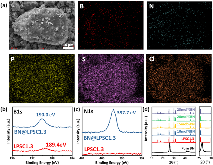
(a) EDS mapping images of BN@LPSC1.3. (b) B 1s and (c) N 1s XPS spectra of LPSC1.3 and BN@LPSC1.3. (d) XRD patterns of pure BN, LPSC1.3 and BN@LPSC1.3 SSEs.

In recent years, lithium-ion batteries (LIBs) have become increasingly popular as portable electric power sources for various applications [1]. With the rapid development of electric vehicles, research attention is drawn to LIBs. However, the use of graphite anodes and flammable organic electrolytes in commercial LIBs results in poor energy density and raises safety concerns. Solid-state electrolytes (SSEs) are considered to address the issues of commercial LIBs using liquid organic electrolytes [2]. Among the SSEs, sulfide SSEs and halide SSEs have high ionic conductivity, which is comparable to or higher than that of liquid electrolytes [3–8]. But halide SSEs are easily reduced by Li metal and mostly are fabricated by high-energy ball milling, which obstructs their commercial use [9]. Therefore, all-solid-state lithium batteries (ASSLBs) that use sulfide SSEs thus offer the most potential when compared to the other types [10].
Among a variety of sulfide SSEs, argyrodite Li7−xPS6−xClx (0 < x ≤ 2) attracted a lot of research interest due to its high ionic conductivity over 10 mS/cm and simple synthesis process [11]. Nevertheless, two disadvantages of argyrodite sulfide SSEs—humidity instability [12] and narrow electrochemical stability window [13]—limited the wide application of argyrodite sulfide SSEs. According to the hard and soft acids and bases theory, the humidity stability can be improved by element substitution, such as partially replacing the P5+ into Sb5+, Sn4+ and As5+ [14–16]. However, the replacement of elements can cause a thermal stability issue with lithium metal [17]. Because replacing the commercial graphite with a lithium metal anode is an efficient way to boost the energy density of ASSLBs [6,7,18], the stability against lithium metal is also relevant [19]. The argyrodite Li7−xPS6−xClx will be reduced by lithium metal due to the limited electrochemical stability window, and the reduction result was proven to be LiCl, Li2S, LixP or P and S [20–23]. If the byproduct layer is an electronic insulator and a lithium ionic conductor, it can still act as the solid electrolyte interface (SEI) [23]. Thus, the LiCl-rich Li6PS5Cl coupled with propylene carbonate could form stable SEI and prevent interfacial reaction [24]. However, if the byproduct layer is an electronic and ionic insulator, it would be harmful to the charge transport at the interface. Pre-designed and generated artificial SEI was covered on the lithium anode to prevent the side reaction. The advantage of artificial SEI is that it is uniform and stable, and the types of artificial SEI could be inorganic (Al2O3 [25] or LiF [26]) or organic (Nafion [27]). However, the instability to humidity is another drawback of sulfide SSEs. Therefore, creating an artificial SEI layer on the lithium anode surface merely addresses the side reaction problem. A core–shell structure of LiF@LGPS was formed via a gas–solid reaction, which was used to address the problems of both the humidity instability and the poor electrochemical stability of sulfide SSEs [28]. LiF@LGPS exhibited greater critical current density (CCD), higher ionic conductivity retention and lower H2S emission after humidity exposure. After 1000 cycles, LiNbO3@LiCoO2/LiF@Li10GeP2S12/Li ASSLB retained 94.8% of its initial capacity [28]. The properties of boron nitride (BN) are well-known for being super thermal conductive and superhydrophobic [29,30]. BN was employed as the electrical insulating and side reaction protecting layer for lithium metal batteries because of the high concentration defects in the BN layer that permit Li ions to penetrate [31–33].
By integrating nano-sized BN into the Li5.7PS4.7Cl1.3 (LPSC1.3) argyrodite sulfide SSE, a core–shell BN@LPSC1.3 SSE is formed in this work. The ionic conductivity is maintained, basically, from 8.09 mS/cm to 6.06 mS/cm, when the SSEs are coated with BN. Additionally, the BN-protected sulfide SSEs showed greater ionic conductivity retention and released less H2S owing to the superhydrophobic feature of BN after being exposed to 1.2%–1.5% relative humidity (RH). Meanwhile, the side reaction between the lithium metal anode and sulfide SSE was suppressed, and the CCD increased from 1.0 mA/cm2 to 2.2 mA/cm2. With a high LiNi0.8Co0.1Mn0.1O2 (NCM811) cathode mass loading of 13.38 mg/cm2, the NCM811/BN@LPSC1.3/Li ASSLB exhibited high discharge capacity retention of 84.34% after 500 cycles at 0.1 C and 25 ℃.
The nano-sized BN was mixed with the LPSC1.3 precursor to synthesise BN@LPSC1.3, and the sintering procedure remained the same as for pure LPSC1.3. The coating amount is 10, 15, 20 and 25 mol%. As the energy-dispersive spectrometry (EDS) displayed in Fig. 1a, the B and N element distributions are well matched with the P, S and Cl element distributions in the LPSC1.3 particle. The nano-sized BN is well dispersed and evenly coated on the particle surface of LPSC1.3. As examined by X-ray photoelectron spectroscopy (XPS) in Figs. 1b and c, the BN@LPSC1.3 sample exhibits a 190.0 eV peak of B 1s and a 397.7 eV peak of N 1s, which is slightly shifted towards the pure BN [34]. Because it is flat for the N 1s spectrum of LPSC1.3 SSE, the weak peak intensity at 189.4 eV may be caused by sample contamination. Furthermore, there are no obvious differences between the BN@LPSC1.3 and LPSC1.3 samples’ C 1s, Li 1s, P 2p, S 2p and Cl 2p spectra (Fig. S1 in Supporting information), suggesting that the nano-BN addition has no effect on the synthesis of LPSC1.3 SSEs. As X-ray diffraction (XRD) is shown in Fig. 1d, the BN@LPSC1.3 SSEs showed the same characteristic peaks as the LPSC1.3 SSE, with no BN peak in the spectra. Because of the low molar mass of BN, the contents of 10, 15, 20 and 25 mol% of BN only occupy 0.93, 1.39, 1.85 and 2.32 mass% of the total mass of BN@LPSC1.3.
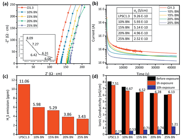
The electronic conductivity of BN is as low as 10−15 S/cm, and the pore diameter of BN is only 1.4 Å, which is smaller than the diameter of Li+ (1.8 Å) [35]. It seems that the BN is an electronic and ionic insulator. However, the defect (such as a boron atom) in BN could enlarge the pore size to 3.11 Å, which enables Li+ in SSEs to pass through [36]. The initial ionic conductivity of LPSC1.3 is 8.09 mS/cm, and it decreases to 7.27 mS/cm for 10 mol% BN coating, further decreasing to 6.42, 6.31 and 6.06 mS/cm for 15, 20 and 25 mol% BN coating, respectively (Fig. 2a). So, the negative effect of BN on ionic conductivity is acceptable. The electronic conductivities of LPSC1.3 SSEs exhibit similar phenomena (Fig. 2b). It is 9.26 × 10⁻¹⁰ S/cm initially and subsequently decreases to 5.93 × 10⁻¹⁰, 5.14 × 10⁻¹⁰, 4.96 × 10⁻¹⁰ and 2.52 × 10⁻¹⁰ S/cm for 10, 15, 20 and 25 mol% BN coatings, respectively. As shown in Fig. S2 (Supporting information), an H2S emission experiment is conducted to examine the resistance of the superhydrophobic BN protective layer to humidity. Subsequently, 1 g of SSE in a 20 mL glass bottle is exposed for 1 h to a closed environment with a RH of 1.2% to 1.5%. With the protection of BN coating, H2S emission dropped from the initial 11.06 ppm to 5.98 ppm for 10 mol% BN coating SSE, then further decreased to 5.29, 3.86 and 3.43 ppm for 15, 20 and 25 mol% BN-coated SSEs (Fig. 2c). However, according to the Nyquist plots in Fig. S3 (Supporting information) and the ionic conductivity evolution in Fig. 2d, the ionic conductivity of LPSC1.3 SSE only dropped from 8.09 mS/cm to 7.51 mS/cm after a 1 h exposure in the closed environment. Similarly, the BN-coated SSEs exhibit no obvious change, and the slightly higher ionic conductivity displayed in the 15 and 25 mol% BN-coated SSEs should be attributed to experimental error. To explore the protective ability of BN coating on ionic conductivity, another humidity exposure experiment was conducted and illustrated in Fig. S4 (Supporting information). Subsequently, 4 g of SSE powder was evenly distributed in a 12.5 cm-diameter petri dish and exposed to a RH 1.2%–1.5% open atmosphere for 10 h. Fig. 2d displays the ionic conductivity, and Fig. S5 (Supporting information) displays the relative Nyquist plots. After a 10 h exposure, LPSC1.3 only acquired 0.19 mS/cm, but the SSEs with 10, 15, 20 and 25 mol% BN coating are 0.53, 0.71, 0.74 and 1.21 mS/cm, respectively. The results revealed that the BN coating on SSEs possesses an outstanding ability to defend against humidity and only has a minor negative impact on the initial ionic conductivity of LPSC1.3.
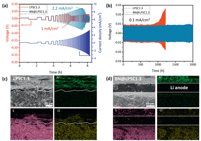
Due to its mechanical and chemical robustness against Li metal, BN could be used to protect the reduction process of solid electrolyte by the Li metal anode [31]. Moreover, the growth of Li dendrite can be inhibited by the ultra-thin BN layer [36]. In this study, 15 mol% BN coated LPSC1.3 (BN@LPSC1.3) was employed to do the electrochemical analysis. As a consequence, as shown in Fig. 3a, the CCD of the Li/LPSC1.3/Li symmetrical cell, in the absence of protection, is only 1.0 mA/cm2, whereas the Li/BN@LPSC1.3/Li symmetrical cell is enlarged to 2.2 mA/cm2. As shown in Fig. 3b, the Li/LPSC1.3/Li cell showed a long-term cycling performance of 1000 h, and then the polarisation voltage started to increase. While the Li/BN@LPSC1.3/Li cell kept a stable lithium plating/stripping for over 2000 h. Upon disassembling the symmetrical cells, a rust surface was visible on both sides of the Li/LPSC1.3 interface (Figs. S6a and b in Supporting information), suggesting a side reaction between LPSC1.3 and the metal mould. In contrast to the Li/LPSC/Li cell, where the lithium plate on both sides was entirely removed, the Li/BN@LPSC1.3/Li cell had only half of the Li plate adhered to the metal mould (Fig. S6c in Supporting information), whereas the opposite side had a portion of SSE adhered to the metal mould side (Fig. S6d in Supporting information). EDS was used to analyse the elemental distribution for the cross-section of both symmetrical cells. For the EDS element mapping in Figs. 3c and d, Al elements originate from the metal mould, and S and Cl elements come from the LPSC1.3 and BN@LPSC1.3 SSEs. In Fig. 3c, the Li anode of the Li/LPSC1.3/Li symmetrical cell nearly disappeared, and the S and Cl elements already overlapped with the Al element, suggesting that the Li anode is consumed by the long-term cycling and LPSC1.3 starts to react with the metal mould, which leads to an increase in polarisation voltage and visible rust. In contrast in Fig. 3d, the Li anode remains in the Li/BN@LPSC1.3/Li cell, and the Al element is limited to the surface of the Li anode. This suggests that the BN inhibited the side reaction between the Li anode and LPSC1.3, which in turn prevented the reaction between LPSC1.3 and metal mould. Figs. S7 and S8 (Supporting information) display the cross-sections of the Li/LPSC1.3/Li and Li/BN@LPSC1.3/Li symmetrical cells. The Li/LPSC1.3/Li cell had small fractures, whereas the Li/BN@LPSC1.3/Li cell displayed a denser pattern.
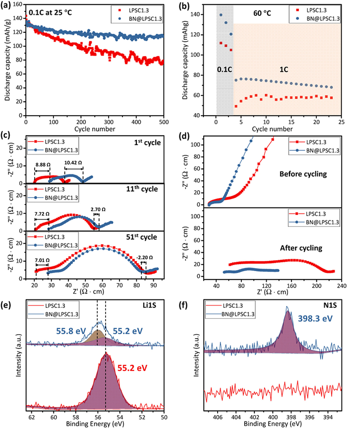
The electrochemical performance of the lithium metal batteries was evaluated using the NCM811 cathode and lithium metal anode, and a high NCM811 mass loading of 13.38 mg/cm2 was used in this study. The long-term cycling performance at 25 ℃ and 0.1 C is shown in Fig. 4a. The initial discharge capacity of the NCM811/BN@LPSC1.3/Li cell is 134.2 mAh/g, whereas that of the LPSC1.3 cell is 133.8 mAh/g. The cell using BN@LPSC1.3 retains 84.34% of its initial discharge capacity after 500 cycles under the protection of BN, whereas the cell using LPSC1.3 only possesses 55.03%. As observed in Fig. 4b, the cells were tested at 0.1 C for 3 cycles at 60 ℃, then cycled at 1 C for 20 cycles. The cell using BN@LPSC1.3 delivered a high initial capacity of 139.7 mAh/g, whereas the cell using LPSC1.3 only presented 111.8 mAh/g. The Nyquist plots of cells using BN@LPSC1.3 and LPSC1.3 at various cycle numbers are displayed in Fig. 4c. Since EIS is a tool to study the resistance between the interfaces in ASSLBs, two or three RQ elements are used to represent the interfaces in the equivalent circuit of ASSLBs [37]. At 100% SOC of the 1st cycle, the series resistance (Rs) of cell using BN@LPSC1.3 SSE is 8.88 Ω greater than that of the cell using LPSC1.3 because of its lower ionic conductivity. Therefore, the resistance at the interfaces (Rint) is represented by the semi-circle scale in Nyquist plots. Thus, the cell using BN@LPSC1.3 still has a 1.54 Ω greater Rint than the cell using LPSC1.3 at the 1st cycle. After 10 cycles and at 100% SOC of the 11th cycle, the Rint of the cell using BN@LPSC1.3 is 5.02 Ω lower than the cell using LPSC1.3, and the difference in Rs decreased to 7.72 Ω. Additionally, at 100% SOC of the 51st cycle, the difference in Rint increases to 9.21 Ω while the difference in Rs is further decreased to 7.01 Ω. For the cells finishing 60 ℃ cycling experiments, the EIS results of the cell (Fig. 4d) using LPSC1.3 demonstrate a considerably larger Rint than that of BN@LPSC1.3, suggesting serious side reactions of bare LPSC1.3 with Li anode at a high temperature of 60 ℃ during 1 C cycling, although their initial EIS are the same with 0.1 C long-cycling testing. The stability of SSEs during long-term cycling and high temperatures (60 ℃) is evaluated and shown in Figs. S9–S11 (Supporting information). For 0.1 C cycling at 25 ℃, both cells maintained a high Coulombic efficiency of approximately 100% (Fig. S9). For 60 ℃ cycling, a superior Coulombic efficiency of apparently 100% is observed for the cell using BN@LPSC1.3, compared to 40%–50% for LPSC1.3 caused by ‘soft short’ (Figs. S10 and S11 in Supporting information) [38]. Using the cell depicted in Fig. S12a (Supporting information), which is obtained from the Al2O3 cylinder, after disassembling the model cells in the Al2O3 cylinders, the Li 1s and N 1s XPS spectra (Figs. 4e and f) are characterised to illustrate the Li/sulfide SSE interface. In the XPS Li 1s spectra, the major peak at ~55.2 eV is attributed to LPSC, and the emerging new peak observed at 55.8 eV could be ascribed to Li3N, which originated from side reactions caused by BN with Li metal [39]. This can also be proven by the others XPS spectra on the Li/BN@LPSC1.3 interfaces (Fig. 4f and Fig. S12 in Supporting information). In Fig. 4f, the N 1s peak of the Li/BN@LPSC1.3 interface shifts to a higher binding energy (from 397.7 eV to 398.3 eV) after cycling at 60 ℃ due to the conversion of BN to Li3N. And the P 2p and S 2p in Fig. S12 shows that the intensity of the newly formed peak (128.0 eV/130.0 eV for P 2p and 160.5 eV/160.2 eV for S 2p) of the cell using BN@LPSC1.3 is weaker than the cell using LPSC1.3, suggesting a suppressed side reaction when employing BN@LPSC1.3 SSE. Therefore, a protective layer similar to SEI will be formed on the surface regardless of whether the BN coating is on the LPSC1.3. However, if coated with BN and Li3N as side reaction products, the contact area of the LPSC1.3 SSE with Li metal will be decreased, and subsequently, the side reaction between the LPSC1.3 SSE and the lithium metal anode will be inhibited. Although some side reaction products between LPSC1.3 and lithium metal (such as Li3P) are beneficial to stability performance, more products with low electronic and ionic conductivities (such as Li2S and S) [20–22] will cause a considerably higher Rint at the interfaces, leading to inferior high-current and rate performances to all-solid-state lithium metal batteries. Thus, although the raw ionic conductivity of LPSC1.3 SSE was higher than that of BN@LPSC1.3 SSE, the side reaction induced interface resistance change was greater, which resulted in worse rate performance.
In conclusion, the precursors of LPSC1.3 are mixed with the nano-sized BN to form an in-situ coating on the LPSC1.3 particle surfaces. Although the BN coating has a slight negative effect on ionic conductivity (from 8.09 mS/cm to 7.27 mS/cm for 10 mol% BN coating), its protections are obvious for the inhibition of H2S emission in a closed environment and the retention of ionic conductivity in an open environment. Due to reduced reactivity with lithium metal, the CCD of the symmetrical cell using BN@LPSC1.3 was increased from 1.0 mA/cm2 to 2.2 mA/cm2. Moreover, the Li/BN@LPSC1.3/Li symmetrical cell achieved stable lithium cycling for over 2000 h at 0.1 mA/cm2. The NCM811/BN@LPSC1.3/Li all-solid-state lithium metal battery at a high cathode mass loading of 13.38 mg/cm2 exhibits 84.34% capacity retention even after 500 cycles at 25 ℃, whereas that using LPSC1.3 is only 55.03%. The NCM811/BN@LPSC1.3/Li cell displayed less ‘soft short’ than that of the cell using LPSC1.3 at the elevated temperature of 60 ℃. A reduced resistance at the interfaces of the cells using BN@LPSC1.3 is observed regardless of ambient temperature (60 ℃) due to the protection of the BN coating. Li3N will be formed on the interface of BN@LPSC1.3 SSE and Li metal, whereas more Li3P and Li2S will be generated without BN coating on the LPSC1.3 SEE. The findings of this work offer an innovative strategy to enhance the stability of LPSC to lithium metal and environmental moisture, which are beneficial to the development of all-solid-state lithium metal batteries.
The authors declare that they have no known competing financial interests or personal relationships that could have appeared to influence the work reported in this paper.
The authors acknowledge financial support from the Science and Technology Project of Shenzhen (Nos. JCYJ20210324094206019 and JCYJ20210324094000001).
Supplementary material associated with this article can be found, in the online version, at doi:
M.S. Ziegler, J.E. Trancik, Energy Environ. Sci. 14 (2021) 1635–1651. doi: 10.1039/d0ee02681f
J. Janek, W.G. Zeier, Nat. Energy 1 (2016) 16141.
Y. Kato, S. Hori, T. Saito, et al., Nat. Energy 1 (2016) 1–7.
Y. Li, S. Song, H. Kim, et al., Science 381 (2023) 50–53.
Y. Tanaka, K. Ueno, K. Mizuno, et al., Angew. Chem. Int. Ed. 62 (2023) e202217581.
J. Wu, L. Shen, Z. Zhang, et al., Electrochem. Energy Rev. 4 (2020) 101–135.
J. Wu, S. Liu, F. Han, X. Yao, C. Wang, Adv. Mater. 33 (2020) 2000751.
S. Chen, D. Xie, G. Liu, et al., Energy Storage Mater. 14 (2018) 58–74.
X. Nie, J. Hu, C. Li, Interdiscip. Mater. 2 (2023) 365–389. doi: 10.1002/idm2.12090
J.K. Hu, H. Yuan, S.J. Yang, et al., J. Energy Chem. 71 (2022) 612–618.
H. Chen, Y. Lu, H. Zhang, et al., Chem. Commun. 59 (2023) 7220–7223. doi: 10.1039/d3cc01387a
Y.T. Chen, M.A.T. Marple, D.H.S. Tan, et al., J. Mater. Chem. A 10 (2022) 7155–7164. doi: 10.1039/d1ta09846b
J.C. Wang, P.F. Wang, T.F. Yi, Energy Storage Mater. 62 (2023) 102958.
L. Ye, E. Gil-González, X. Li, Electrochem. Commun. 128 (2021) 107058.
P. Lu, L. Liu, S. Wang, et al., Adv. Mater. 33 (2021) e2100921.
G. Sahu, Z. Lin, J. Li, et al., Energy Environ. Sci. 7 (2014) 1053–1058.
Y. Wu, J. Xu, P. Lu, et al., Adv. Energy Mater. 13 (2023) 2301336.
Q. Zhang, Z. Ding, G. Liu, et al., Energy Storage Mater. 23 (2019) 168–180.
Y.L. Liao, J.K. Hu, Z.H. Fu, et al., J. Energy Chem. 80 (2023) 458–465.
C. Zheng, J. Zhang, Y. Xia, et al., Small 17 (2021) e2101326.
T.K. Schwietert, V.A. Arszelewska, C. Wang, et al., Nat. Mater. 19 (2020) 428–435. doi: 10.1038/s41563-019-0576-0
S. Narayanan, U. Ulissi, J.S. Gibson, et al., Nat. Commun. 13 (2022) 7237.
S. Li, S.J. Yang, G.X. Liu, et al., Adv. Mater. 36 (2023) 2307768.
Y. Li, W. Arnold, J.B. Jasinski, et al., Electrochim. Acta 363 (2020) 137128.
S. Cui, X. Wu, Y. Yang, et al., ACS Energy Lett. 7 (2021) 42–52. doi: 10.2117/psysoc.2019-a108
J. Tan, J. Matz, P. Dong, J. Shen, M. Ye, Adv. Energy Mater. 11 (2021) 2100046.
T. Yan, F. Li, C. Xu, H.T. Fang, Electrochim. Acta 410 (2022) 140004.
Y. Jin, Q. He, G. Liu, et al., Adv. Mater. 35 (2023) e2211047.
L.H. Li, Y. Chen, Langmuir 26 (2009) 5135–5140.
Q. Cai, D. Scullion, W. Gan, et al., Sci. Adv. 5 (2019) eaav0129.
Q. Cheng, A. Li, N. Li, et al., Joule 3 (2019) 1510–1522.
J. Xie, L. Liao, Y. Gong, et al., Sci. Adv. 3 (2017) eaao3170.
G. Li, H. Li, Y. Wang, et al., ACS Appl. Mater. Interfaces 13 (2021) 56109–56115. doi: 10.1021/acsami.1c15980
Z. Xu, Y. Chen, W. Li, et al., RSC Adv. 8 (2018) 17944–17949. doi: 10.1039/c8ra02017e
C. Steinborn, M. Herrmann, U. Keitel, et al., J. Eur. Ceramic Soc. 33 (2013) 1225–1235.
K. Yan, H.W. Lee, T. Gao, et al., Nano Lett. 14 (2014) 6016–6022. doi: 10.1021/nl503125u
S. Hori, R. Kanno, X. Sun, et al., J. Power Sources 556 (2023) 232450.
J. Xiao, Q. Li, Y. Bi, et al., Nat. Energy 5 (2020) 561–568. doi: 10.1038/s41560-020-0648-z
L. Chen, T. Gu, J. Ma, et al., Nano Energy 100 (2022) 107470.

Figure 1 (a) EDS mapping images of BN@LPSC1.3. (b) B 1s and (c) N 1s XPS spectra of LPSC1.3 and BN@LPSC1.3. (d) XRD patterns of pure BN, LPSC1.3 and BN@LPSC1.3 SSEs.

Figure 2 (a) Nyquist plots and corresponding ionic conductivity of LPSC1.3 and BN@LPSC1.3 SSEs. (b) Direct-current polarisation curves and corresponding electronic conductivity of LPSC1.3 and BN@LPSC1.3 SSE. (c) H2S emission of 1-h exposure in a closed environment. (d) Ionic conductivity evolution from initial to 1-h exposure in a closed environment and 10-h exposure in an environment.

Figure 3 (a) Galvanostatic cycling of Li/LPSC1.3/Li and Li/BN@LPSC1.3/Li cells for CCD measurement with a 0.1 mA/cm2 one-step increased current density. (b) Long-term cycling performances of Li/LPSC1.3/Li and Li/BN@LPSC1.3/Li cells at 0.1 mA/cm2. The cross-section and corresponding elemental mappings of (c) Li/LPSC1.3/Li and (d) Li/BN@LPSC1.3/Li cells.

Figure 4 (a) The discharge capacity of NCM811/LPSC1.3/Li and NCM811/BN@LPSC1.3/Li for long-term cycling performance at 0.1 C and 25 ℃. (b) The 60 ℃ high temperature cycling performance at 1 C for NCM811/LPSC1.3/Li and NCM811/BN@LPSC1.3/Li cells. EIS results of the cells (c) cycled at 0.1 C and 25 ℃ and (d) cycled at 1 C and 60 ℃. (e) Li 1s and (f) N 1s XPS spectra of Li/LPSC1.3 and Li/BN@LPSC1.3 interfaces of the cells after 60 ℃ high temperature cycling.

 扫一扫看文章

扫一扫关注我们
 DownLoad:
 下载:
下载:
 下载:
下载: