Figure 1.
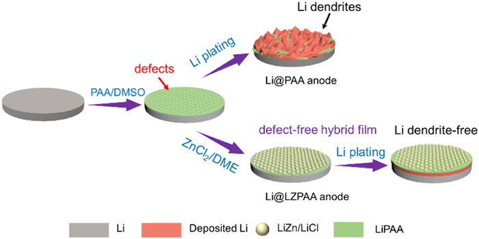
Schematic diagram of fabrication process for defect-free hybrid film on the Li metal electrode, and Li deposition on the surface of Li@PAA and Li@LZPAA.
Li-Zn alloy patch for defect-free polymer interface film enables excellent protection effect towards stable Li metal anode
Zihao Wang , Jing Xue , Zhicui Song , Jianxiong Xing , Aijun Zhou , Jianmin Ma , Jingze Li

Lithium (Li) metal with high specific capacity (3860 mAh/g) and lowest electrode potential (-3.04 V vs. the standard hydrogen electrode) is considered to be the ideal anode material for next-generation Li batteries [1–5]. However, metallic Li can spontaneously react with liquid electrolytes to form a solid electrolyte interphase (SEI) layer that is of poor quality, which would be incapable of tolerating the volume fluctuations and induces the growth of Li dendrites [6–11]. Thus, the practical application of Li metal anode is seriously hindered.
Recently, various strategies have been proposed for addressing these problems, including the preparation of three-dimensional (3D) host architectures [9,12–16], novel electrolyte additives [17–19], and the construction of artificial SEI layers to improve the stability of Li metal anode [20–28]. Ideally, an artificial SEI layer should address the large volume change during dynamic Li plating/stripping processes. Therefore, the polymeric films have been developed to strengthen the stability of Li/electrolyte interface due to their convenient fabrication process and high flexibility. Various polymeric films with high binding ability, conformality and superior ionic conductivity have been proposed [28–32]. For example, Guo et al. [33] fabricated a LiPAA artificial SEI layer with high elasticity to stabilize the Li plating/stripping. The flexible and Li+ conductive LiPAA can accommodate Li deposition during the cycling. However, the poor film-forming properties of LiPAA limit its electrochemical performance. Therefore, Wei et al. introduced polyvinyl alcohol (PVA) to improve the integrity of the LiPAA film [34]. Alternatively, the polymer-inorganic composite layer employing Li alloy and Li halide as the filler has attracted much attentions since the enhanced mechanical stability can further prevent the corrosion of Li metal by the liquid electrolyte [35–37]. For example, Zhang et al. [38] coated a double-layer film consisting of Li-Sb alloy and polymeric rubber layers to protect the Li metal anode. Apparently, the double-layered design combines the merits of both the Li alloy and the stretchable polymer, in which the favorable Li affinity and fast Li transport capability of the bottom alloy layer can achieve uniform Li deposition, and high mechanical flexibility of the top polymer layer can mitigate volume changes and maintain the geometric integrity of the alloy layer as well as the bulk Li anode. Thus, the double-layer configuration results in extended cycling lifespan for 500 h in a symmetric cell with an areal capacity of 1 mAh/cm2. Unfortunately, the intrinsic porosity and pinholes in the solution-fabricated polymer film cannot mitigate the corrosion of Li metal caused by the liquid electrolyte. Moreover, the swelling of the polymer matrix in the liquid electrolyte is also inevitable, which allows slow electrolyte penetration through the protective film without good dimensional integrity and limits the cycle life of the cells [39]. Therefore, it would be highly desirable to construct a defect-free protection film that simultaneously offers the superiority of the polymeric film with high flexibility and the perfect separation effect for eliminating the liquid electrolyte corrosion of Li metal anode.
Herein, a pinhole-free composite film, consisting of a Li-Zn alloy/LiCl hybrid layer and Li+ ion-conducting LiPAA polymer interphase layer, was fabricated to protect Li metal anode (denoted as Li@LZPAA) by a simple double coating method. The LiPAA layer covers the surface of metallic Li anode in the first step, and then the defects of the polymer matrix are self-repaired by Li-Zn alloy composite particles via spreading ZnCl2 solution on the polymer film surface. The Li-Zn alloy as the patch for LiPAA membrane achieves a defect-free hybrid film, which is nailed flat against the Li anode and exhibits extraordinary structure stability in the liquid electrolyte, eliminating the swelling and liquid permeability corrosion of the polymer membrane by the liquid electrolyte and enabling perfect protection effect for LiPAA. In addition, LiPAA polymer matrix randomly distributed among Li-Zn alloy/LiCl composite particles alleviates the reduced Li atoms on the top surface of the hybrid film and enhances the Li+ transport capability, resulting in uniform Li deposition underneath the protection layer and avoiding the formation of Li dendrites (Fig. 1). As a result, Li@LZPAA anode can achieve dendrite-free Li plating/stripping morphology and excellent cyclic stability.
The as-obtained artificial protective layer shown in Fig. 1 was created on the surface of Li foil by a simple and low-cost two-step coating strategy. After PAA solution was dripped onto the surface of the Li foil to fabricate the Li@PAA electrode, the color of the Li foil turns white and the SEM images present the rough surface of Li@PAA, which can be attributed to the limited film formation capability and high porosity (Figs. 2a and b). In addition, the thickness of the LiPAA polymer membrane is about 5 µm (Fig. 2c). As previously reported, the LiPAA polymer has high tensile properties and can automatically adjust stress strength by the strain variation, which acts as a good choice for polymer protective layer [33]. Subsequently, the Li-Zn alloy layer was achieved by a drip-coating ZnCl2 solution approach. It was found that the surface of Li@PAA electrode began to turn black, indicating that the in-situ formation of LiZn/LiCl alloy layer occurs according to the following equations:
|
|
(1) |
|
|
(2) |
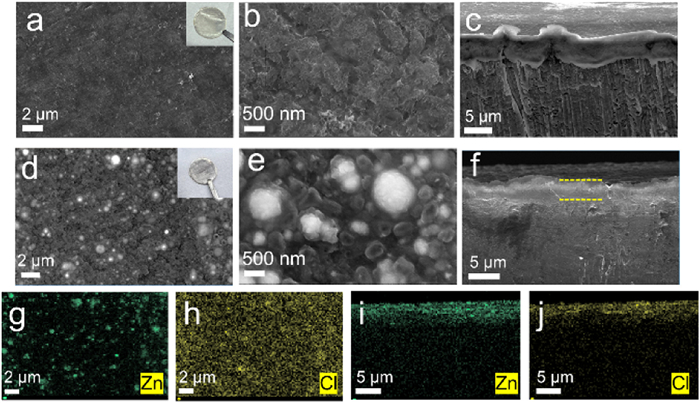
The LiZn peaks are identified in XRD pattern of Li@LZPAA anode (Fig. S1 in Supporting information), reflecting that ZnCl2 reacts with Li successfully to form LiZn and LiCl. The top-view SEM image of the as-synthesized Li@LZPAA electrode shows that the layer surface is smooth and some densely white nanoparticles are distributed on the surface (Fig. 2d). The corresponding EDS mapping image indicates that the white particles consist of LiZn and LiCl composite (Figs. 2g and h), indicating that the LiPAA polymer network can be partially covered by the Li-Zn alloy particles. The thickness of hybrid film formed on the surface of Li metal is ~5 µm, which is close to the coated polymer layer thickness of Li@PAA electrode (Figs. 2c and f). The side-view EDS mapping images of Li@LZPAA electrode demonstrate that the hybrid film is nailed flat against the Li anode (Figs. 2i and j). Furthermore, the Li-Zn alloy particles as the patches fill up the pinholes of LiPAA matrix completely and achieve the pore-free morphology (Fig. 2e). Therefore, the hybrid film can be nailed flat against the Li anode by Li-Zn alloy particles stably, improving the integrity of the membrane. In addition, the Li@LZPAA and Li@PAA electrodes have similar Raman characteristic peaks (Fig. S2 in Supporting information), demonstrating that the LiPAA polymer network is not damaged after the introduction of the Li-Zn alloy layer [40]. Moreover, it can be observed that there are more white particles on the surface of Li@LiZn electrode than that of Li@LZPAA electrode (Fig. S3 in Supporting information), indicating that some LiZn alloy particles are dispersed in the interior of PAA film and the LiPAA polymer membrane is partially covered by the Li-Zn alloy particles. Furthermore, the surface morphology of the hybrid film does not change significantly with the increase of PAA solution concentration up to 0.3% (Fig. S4 in Supporting information), indicating that the LiPAA membrane can still be self-filled by LiZn alloy patches. Notably, the operation sequence of the drip-casting polymer and Li alloy layer is the key factor. Neither PAA mixed with ZnCl2 solution followed by a single coating nor ZnCl2 solution was dropped on the Li metal firstly enabling the formation of the required hybrid film (Figs. S5a and b in Supporting information), exhibiting rough surface with a large number of white particles at micrometer scale unevenly, which is insufficient to form a pinhole-free hybrid film. Therefore, the formation of Li-Zn alloy patch on LiPAA interphase layer is the key factor for the construction of the advanced hybrid passivation film.
In order to prove the integrity of the hybrid film and the ability to suppress interface side reactions, the impedance analysis was employed on the symmetrical Li cell. The impedance evolution of Li@PAA and Li@LZPAA cells for different resting times at room temperature are shown in Fig. S6 (Supporting information). Regarding the Li@PAA cell, the resistance is monotonously increased from ~220 Ω at 0 h to ~570 Ω at the 48 h as a function of the storage time, indicating that LiPAA membrane is insufficient to effectively isolate the electrolyte and Li metal anode due to the pinholes. On the contrary, the Li@LZPAA cell exhibits a slow growth of resistance from ~180 Ω at 0 h to ~330 Ω at the 48 h, maintaining a relatively stable impedance change. These results demonstrate that the hybrid film can act as a defect-free protection layer to suppress interface side reactions efficiently.
In order to further confirm the role of the hybrid protection film, Li plating/stripping measurements were carried out in the symmetric cells containing the pristine Li, Li@PAA, Li@LiZn and Li@LZPAA as the electrodes, respectively (Fig. 3a). Under the test condition of 1 mAh/cm2 and 1 mA/cm2, the symmetric cell with bare Li electrodes displays the poorest performance. The overpotential of the cell with bare Li electrodes increases to 1000 mV at 350 h. In contrast, Li@PAA anode can cycle steadily for more than 700 h due to the favorable flexibility. However, the overpotential of Li@PAA anode gradually increases after 700 h and even rises to 500 mV, indicating that the soft LiPAA layer with the defects is difficult to prevent the growth of Li dendrites. Similarly, the Li@LiZn anode shows a stable voltage profile over 700 h due to the protection of the Li-Zn alloy and LiCl composite particles, but the repeated Li plating/stripping behavior eventually leads to the destruction of the alloy composite layer and the failure of the cell. In comparison, Li@LZPAA anode exhibits a stable voltage profile with the lower overpotential (~25 mV) over 2800 h, giving rise to a remarkably improved stability compared with the other electrodes. The significant improvement in cycling life proves that the perfect protection effect of the pore-free hybrid film of Li alloy layer and Li+ ion conducting polymer network, which enhances the Li+ transport capability and improves the structural stability. When the current density is promoted to a higher level of 3 mA/cm2, the Li/Li cell succumbed to substantial voltage fluctuation at only 100 h, which could be explained by the accumulation of SEI layers and Li dendrites. Notably, the effect of a single protective film coated on Li metal (Li@PAA and Li@LiZn) will be greatly weakened under high current density, indicating that the swelling/corrosion of the electrolyte for the polymer and the deposited Li accumulated on the damaged LiZn/LiCl composite layer surface can be one of the reasons leading to cell failure. By deep contrast, the Li@LZPAA anode demonstrates flat voltage plateau (~40 mV) for more than 800 h, which avoids the damage of the Li-Zn alloy and the swelling/corrosion of the LiPAA network, realizing a more stable Li plating/stripping behavior. The Li@LZPAA anode also has favorable stability in carbonate-based electrolyte. Fig. S7 (Supporting information) exhibits the electrochemical performance of these Li anodes in ester electrolyte. The Li@LZPAA anode has stable voltage profiles and longer cycling lifespan up to 1100 h under a condition of 1 mA/cm2, 1 mAh/cm2, which is higher than that of Li, Li@PAA and Li@LiZn anodes. Even when the current is increased to 3 mA/cm2, the Li@LZPAA symmetric cell can still cycle for 330 h, indicating the perfect protection effect of the defect-free hybrid film.

The EIS tests were taken to analyze the interfacial stability at the electrode/electrolyte interface before and after cycling. The fitted impedance results were shown in Fig. S8 (Supporting information). The high frequency semicircle and mid-frequency semicircle are associated with SEI resistance (Rs) and charge transfer resistance (Rct), respectively. The Rs of Li symmetrical cell (510.3 Ω) is lower than that of Li@LZPAA symmetrical cell (290.2 Ω) prior to the cycling, which can be attributed to the low conductivity of the natural passivation layer on the surface of Li metal. After 50 cycles, the Rs of the Li symmetrical cell falls sharply to 142.9 Ω, indicating that the breakage of the SEI layer exposes fresh Li in the liquid electrolyte leading to the formation of a large number of Li dendrites with high specific area. The unstable interface resulted in an enlarged impedance change. In contrast, the Rs value of Li@LZPAA symmetrical cell is 118.0 Ω after 50 cycles, reflecting the impedance change is much lower. This trend demonstrates a more stable electrode/electrolyte interface and fewer Li dendrites, proving the prefect passivation effect of the defect-free hybrid film. In addition, the performance is better than those of previously reported electrodes using artificial SEI layers such as polymer, inorganic specie or traditional polymeric-inorganic hybrid film (Table S1 in Supporting information).
In addition, the excellent plating behaviors of the Li@LZPAA anode can be observed by in situ optical microscope (Fig. 3b). The gap between two Li or Li@LZPAA electrodes was filled with the liquid electrolyte. The Li deposition on the bare Li foil rapidly evolves into Li dendrite clusters scattered along the Li/electrolyte interface after 30 min at 3 mA/cm2, while there are almost no Li dendrites on the surface of Li@LZPAA electrodes. With more Li deposition (60 min), these Li dendrites clusters gradually evolve into thick Li dendrites with larger size, which gives serious safety risks. In contrast, the surface of the Li@LZPAA anode is still smooth after a 60 min Li plating, suggesting uniform Li+ flux and Li nucleation. This indicates that the strong inhibition effect of Li dendrites growth by the robust hybrid film guides the uniform Li deposition underneath the film and prevents the film from breaking by volume variation. The favorable Li plating behavior can be also confirmed by the ex-situ SEM images (Fig. S9 in Supporting information). Compared with the original Li@LZPAA morphology, the surface of Li@LZPAA has no obvious evolution, exhibiting the alloy composite particle morphology is stable and no Li dendrites signals appear after Li plating 3 mAh/cm2, which implies the advanced hybrid layer enhances the Li+ transport and structural integrity effectively.
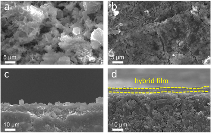
To further assess the effects of the hybrid film, the morphologies of Li and Li@LZPAA electrodes after 50 cycles were investigated by SEM. Fig. 4a shows that obvious Li dendrite clusters appear on the surface of the bare Li foil after 50 cycles at 3 mA/cm2, in accordance with the above poor cycling performance of Li symmetric cells. In addition, the cross-sectional view SEM image of the pristine Li anodes also exhibits rough morphology with Li dendrite clusters (Fig. 4c). In contrast, the surface of the Li@LZPAA anode is smooth and dense without Li dendrites (Fig. 4b). Meanwhile, the cross-sectional image shows a dense structure and the thickness of the film is almost unchanged after cycling (Fig. 4d), indicating that Li plating/stripping behavior occurs underneath the protective film during cycling. The Li-Zn alloy as the patch of polymeric film can inhibit the formation of Li dendrites and enable perfect protection for LiPAA film effectively. Moreover, the hybrid film exhibits excellent durability even after 100 cycles under a condition of 3 mA/cm2, 1 mAh/cm2, and the Li@LZPAA anode displays a dendrite-free morphology (Fig. S10a in Supporting information). The hybrid protective film remains intact and shows favorable dimensional integrity on the Li metal surface, as shown in the corresponding side-view SEM image (Fig. S10b in Supporting information). Notably, the Zn element is primarily observed in the hybrid film, which is ascribed to the electrochemical "inertness" of Li-Zn alloy particles during the cycling, ensuring the long-term effective protective effect of the defect-free hybrid film.
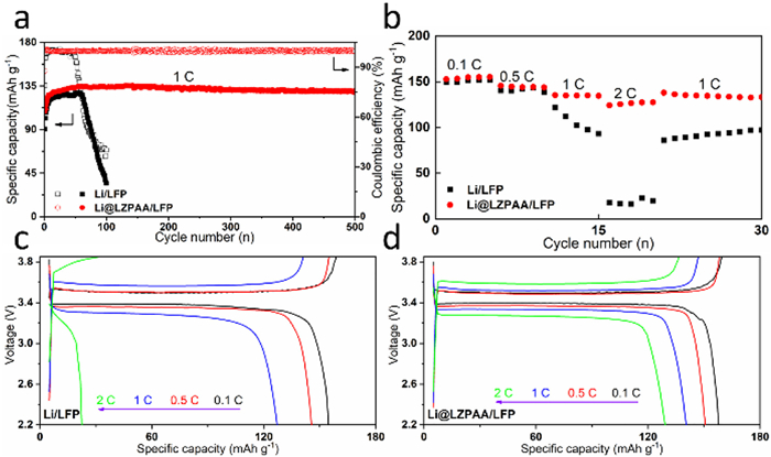
The performance of Li@LZPAA as anode was further evaluated in a full cell using LFP as the cathode. The cycle and rate performance of the cells were tested. Fig. 5a shows the cycling performances of LFP cathodes coupled with bare Li and Li@LZPAA anodes. The Li/LFP cell illustrates the discharge specific capacity is ~125 mAh/g for 50 cycles, and quickly drops to 34 mAh/g less than 100 cycles, accompanied by the fluctuating CE. The poor cycling performance can be ascribed to the unstable SEI and Li dendrites growth. In comparison, the cycle life of the Li@LZPAA/LFP cell is greatly extended to 500 cycles with a capacity retention of 95.5% and stable CE, indicating that the loss of active Li is minimal. The rate performance of these cells is compared in Fig. 5b. The Li@LZPAA cell delivers favorable reversible discharge capacities of ~153, 146, 135 and 124 mAh/g at 0.1, 0.5, 1 and 2 C, respectively, which are much higher than those of the pristine Li/LFP cell (Figs. 5c and d). Notably, the significant difference in discharge capacity can be observed at 2 C, reflecting the Li@LZPAA has a more stable Li+ transport at higher current density. Moreover, when the rate returns to 1 C, the capacity of the Li/LFP cell does not fully recover, whereas the Li@LZPAA/LFP cell can recover. Thus, the results of the LFP-based full cells prove that the hybrid film with unique architecture can stabilize the anode/electrolyte interface and significantly enhance the structural stability of the Li-Zn alloy and LiPAA, which improves the electrochemical performance of the full cells.
In summary, we have developed a unique hybrid film consisting of LiPAA polymer as artificial interface layer and Li-Zn alloy as the patch by a facile and inexpensive strategy to stabilize Li metal anode. The Li-Zn alloy composite particles repair the pinhole leaks of the LiPAA film and the defect-free hybrid film is nailed flat against the Li anode, offering excellent dimensional stability in the liquid electrolyte, which alleviates the swelling/liquid permeability and enables perfect protection effect of the LiPAA membrane. Additionally, the LiPAA network as a binder with good flexibility endows favorable contact with LiZn/LiCl particles and improves the structural stability of Li-Zn alloy layer. Therefore, the hybrid film compensates the shortage of the traditional polymer layer in the liquid electrolyte system. The synergetic effect between the patch of Li alloy and the LiPAA polymer membrane gives rise to the composite Li anode with significantly improved cycling stability and a dendrite-free morphology. In particular, the Li@LZPAA symmetric cell can cycle for 2800 h at a current density of 1 mA/cm2 with a fixed areal capacity of 1 mAh/cm2, and the LFP-based full cell has an ultralong cycle life of 500 cycles at 1 C with a capacity retention of 95.5% and exhibits excellent rate performance at a high areal capacity of LFP (2.45 mAh/cm2). This work provides a novel idea for the designing of the polymer-Li alloy composite layer, demonstrating that the advanced hybrid protective layer significantly improves the stability of Li metal anode for practical application.
The authors declare that they have no known competing financial interests or personal relationships that could have appeared to influence the work reported in this paper.
This work was partly supported by the National Natural Science Foundation of China (Nos. 22379019 and 52172184) the Science and Technology Department of Sichuan Province of China (No. 24GJHZ0444) and S&T Special Program of Huzhou (No. 2023GZ03).
Supplementary material associated with this article can be found, in the online version, at doi:
J.B. Goodenough, Y. Kim, Chem. Mater. 22 (2010) 587–603. doi: 10.1021/cm901452z
D. Liu, C. Chen, X. Xiong, Acta Phys. Chim. Sin. 37 (2021) 202008078.
M.S.A. Rahaman, A.F. Ismail, A. Mustafa, Polym. Degrad. Stab. 92 (2007) 1421–1432. doi: 10.1016/j.polymdegradstab.2007.03.023
P. Shi, X.Q. Zhang, X. Shen, et al., Adv. Mater. Technol. 5 (2019) 1900806.
G. Wang, C. Chen, Y. Chen, et al., Angew. Chem. Int. Ed. 59 (2020) 2055–2060. doi: 10.1002/anie.201913351
J. Ko, Y.S. Yoon, Thin Solid Films 673 (2019) 119–125. doi: 10.1016/j.tsf.2019.01.048
Z.A. Ghazi, Z. Sun, C. Sun, et al., Small 15 (2019) e1900687. doi: 10.1002/smll.201900687
Y. Zhao, Y. Ye, F. Wu, et al., Adv. Mater. 31 (2019) e1806532. doi: 10.1002/adma.201806532
W. Jia, T. Chen, Y. Wang, et al., Electrochim. Acta 309 (2019) 460–468. doi: 10.1016/j.electacta.2019.04.054
X. Wang, J. Zhuang, M. Liu, et al., J. Mater. Chem. A 7 (2019) 19104–19111. doi: 10.1039/C9TA06500H
W. Tang, X. Yin, S. Kang, et al., Adv. Mater. (2018) e1801745.
Y. Zhao, S. Hao, L. Su, Z. Ma, G. Shao, Chem. Engin. J. 392 (2020) 123691. doi: 10.1016/j.cej.2019.123691
Z. Wang, J. Xue, Y. Liu, et al., Sci. China Mater. 65 (2021) 69–77.
T. Wei, J. Lu, P. Zhang, et al., Chin. Chem. Lett. 34 (2023) 107947. doi: 10.1016/j.cclet.2022.107947
H. Zhang, S. Ju, G. Xia, D. Sun, X. Yu, Adv. Funct. Mater. 31 (2021) 2009712. doi: 10.1002/adfm.202009712
Z. Wang, Y. Liu, J. Xing, et al., Research 2022 (2022) 9843093. doi: 10.34133/2022/9843093
X. Fan, L. Chen, O. Borodin, et al., Nat. Nanotechnol. 13 (2018) 715–722. doi: 10.1038/s41565-018-0183-2
H. Yang, C. Guo, J. Chen, et al., Angew. Chem. Int. Ed. 58 (2019) 791–795. doi: 10.1002/anie.201811291
Y. Yang, J. Xiong, S. Lai, et al., ACS Appl. Mater. Interfaces 11 (2019) 6118–6125. doi: 10.1021/acsami.8b20706
Y. Cai, Q. Jin, K. Zhao, et al., J. Alloys Compd. 900 (2022) 163444. doi: 10.1016/j.jallcom.2021.163444
D. Chen, S. Huang, L. Zhong, et al., Adv. Funct. Mater. 30 (2019) 1907717.
Z. Hu, S. Zhang, S. Dong, et al., Chem. Mater. 29 (2017) 4682–4689. doi: 10.1021/acs.chemmater.7b00091
D. Kang, S. Sardar, R. Zhang, et al., Energy Storage Mater. 27 (2020) 69–77. doi: 10.1016/j.ensm.2020.01.020
K. Li, Y. Wang, W. Jia, et al., ACS Appl. Mater. Interfaces 12 (2020) 2285–2292. doi: 10.1021/acsami.9b16083
S. Li, Y. Huang, C. Luo, et al., Chem. Eng. J. 399 (2020) 125687. doi: 10.1016/j.cej.2020.125687
Y. Yu, G. Huang, J.Z. Wang, et al., Adv. Mater. 32 (2020) e2004157. doi: 10.1002/adma.202004157
W. Cao, J. Lu, K. Zhou, et al., Nano Energy 95 (2022) 106983. doi: 10.1016/j.nanoen.2022.106983
Z. Zhou, Y. Feng, J. Wang, et al., Chem. Eng. J. 396 (2020) 125254. doi: 10.1016/j.cej.2020.125254
Y. Zhao, D. Wang, Y. Gao, et al., Nano Energy 64 (2019) 103893. doi: 10.1016/j.nanoen.2019.103893
G. Wang, C. Chen, Y. Chen, et al., Angew. Chem. Int. Ed. 59 (2019) 2055–2060.
Z. Gao, S. Zhang, Z. Huang, et al., Chin. Chem. Lett. 30 (2019) 525–528. doi: 10.1016/j.cclet.2018.05.016
Z. Wang, Z. Song, Y. Liu, et al., Phys. Chem. Chem. Phys. 25 (2022) 124–130.
N.W. Li, Y. Shi, Y.X. Yin, et al., Angew. Chem. Int. Ed. 57 (2018) 1505–1509. doi: 10.1002/anie.201710806
C. We, J. Deng, J. Xing, et al., Nanoscale Adv. 5 (2023) 5094–5101. doi: 10.1039/D3NA00248A
Y. Lin, Z. Wen, C. Yang, P. Zhang, J. Zhao, Electrochem. Commun. 108 (2019) 106565. doi: 10.1016/j.elecom.2019.106565
Q. Pang, X. Liang, I.R. Kochetkov, P. Hartmann, L.F. Nazar, Angew. Chem. Int. Ed. 57 (2018) 9795–9798. doi: 10.1002/anie.201805456
Z. Wang, S. Xie, X. Gao, et al., Chin. Chem. Lett. 34 (2023) 108151. doi: 10.1016/j.cclet.2023.108151
Y. Zhang, G. Wang, L. Tang, et al., J. Mater. Chem. A 7 (2019) 25369–25376. doi: 10.1039/C9TA09523C
C. Fu, C. Battaglia, ACS Appl. Mater. Interfaces 12 (2020) 41620–41626. doi: 10.1021/acsami.0c13485
B. Han, M.J. Piernas-Muñoz, F. Dogan, et al., J. Electrochem. Soc. 166 (2019) A2396–A2402. doi: 10.1149/2.0241912jes

Figure 1 Schematic diagram of fabrication process for defect-free hybrid film on the Li metal electrode, and Li deposition on the surface of Li@PAA and Li@LZPAA.

Figure 2 (a, b) Top-view and (c) side-view SEM images of Li@PAA anode. (d, e) Top-view SEM images and (g, h) the corresponding EDS mapping of Li@LZPAA. (f) Cross-sectional SEM image and (i, j) the corresponding EDS mapping images of Li@LZPAA.

Figure 3 (a) The voltage profiles of the pristine Li metal, Li@PAA, Li@LiZn and Li@LZPAA symmetrical cells at different current densities of 1 mA/cm2 and 3 mA/cm2 with fixed areal capacity of 1 mAh/cm2, separately. (b) In situ optical images of these symmetrical cells taken at different time intervals at 3 mA/cm2.

Figure 4 The top-view and side-view SEM images of (a, c) bare Li and (b, d) Li@LZPAA anodes of the Li/Li symmetric cell after 50 cycles at 3 mA/cm2.

 扫一扫看文章

扫一扫关注我们
 DownLoad:
 下载:
下载:

 下载:
下载: