Citation:
Yun-Xin Huang, Lin-Qian Yu, Ke-Yu Chen, Hao Wang, Shou-Yan Zhao, Bao-Cheng Huang, Ren-Cun Jin. Biochar with self-doped N to activate peroxymonosulfate for bisphenol-A degradation via electron transfer mechanism: The active edge graphitic N site[J]. Chinese Chemical Letters,
2024, 35(9): 109437.
doi:
10.1016/j.cclet.2023.109437
Biochar with self-doped N to activate peroxymonosulfate for bisphenol-A degradation via electron transfer mechanism: The active edge graphitic N site
English
Biochar with self-doped N to activate peroxymonosulfate for bisphenol-A degradation via electron transfer mechanism: The active edge graphitic N site
School of Engineering, Hangzhou Normal University, Hangzhou 311121, China
b.
Zhejiang Provincial Key Laboratory of Urban Wetlands and Regional Change, Hangzhou 311121, China
* Corresponding author at: School of Engineering
Hangzhou Normal University
Hangzhou 311121
China. E-mail address: huangbc@hznu.edu.cn (B.-C. Huang). 1 These authors contributed equally to this work.
Received Date:
25 September 2023 Accepted Date:
13 December 2023 Revised Date:
22 November 2023 Available Online:
15 September 2024
Abstract:
Environmental endocrine disruptors, represented by bisphenol A (BPA), have been widely detected in the environment, bringing potential health risks to human beings. Nitrogen-containing biocarbon catalyst can activate peroxymonosulfate (PMS) to degrade BPA in water, but its active sites remain opaque. Herein, in this work, nitrogen-containing biochar, i.e., CNedge, enriched with graphitic-N defects at the edges was prepared by one-pot co-pyrolysis of chitosan and potassium carbonate. The results showed that the CNedge/PMS system can effectively degrade 98% of BPA (50 mg/L). The electron transfer based non-radical oxidation mechanism was responsible for BPA degradation. Edge graphitic-N doping endows biochar with strong electron transfer ability. The catalyst had good recovery and reuse performance. This catalytic oxidation was also feasible for other refractory pollutants removal and worked well for treating practical wastewater. This work may provide valuable information in unraveling the N doping configuration-activity relationship during activating PMS by biochar.
With the ever-increased desire on designing environmental benign material for wastewater remediation, carbon-based catalysts are gaining extensive attentions by researchers [1,2]. Carbon materials own peculiarities of large specific surface area, abundant reserves, and acid/alkali resistance, which endows its great potential for practical application. Advanced oxidation process is widely used to degrade and mineralize organic pollutants due to its ability to produce highly reactive substances. The choice of oxidant is crucial in advanced oxidation process, which includes peroxymonosulfate (PMS), peroxydisulfate, hydrogen peroxide as well as peracetic acid [3,4]. In the past years, carbon materials were found efficaciously in PMS activation [5–7]. However, the degree of graphitization [8], type of oxygen-containing functional groups on the surface [9], porosity [10], and metal or mineral impurities [11] all take effect on catalytic activity. Therefore, it is of extraordinary significance to improve the PMS activation efficiency of non-nano carbon materials and elucidate their active centers.
Through theoretical simulation and experimental verification, nitrogen doping can regulate the electronic structure of the six membered carbon ring of carbon material, promoting the electron-transfer ability [12] and enhancing catalytic activity of carbon materials. The doped nitrogen can actually assume different configurations, including pyridinic N, pyrrolic N, and graphitic N [13]. Due to the diversity and variability of different nitrogen configurations in the persulfate activation system, extensive studies are still needed to reveal the N doping configuration-activity relation in biochar based catalytic materials.
Based on the available literature reports, it is known that graphitic N had two different positional isoforms, namely graphitic center N located in the plane and graphitic edge N located at the edge [14]. The graphitic N in the planar center was considered to be the intrinsic active site for O—O bond cleavage to produce 1O2 in PMS, which was responsible for organic matter degradation [15]. In another study, it was revealed that the gradual removal of the carbon edge unstable N configuration under high-temperature pyrolysis induced a conformational transition from graphitic-centered N to graphitic-edge N sites [14]. The edge graphitic N can also be imaginatively referred to as "fjord edge N" [16], and this spatial effect has a great impact on material catalytic activity. Herein, we might be able to construct an electron transfer regime dominated non-radical oxidation system for refractory pollutants removal via modulating the N doping configuration of biochar.
The inspiration of this work came from the fact that the carbon and nitrogen in the biomass such as chitosan will partially volatilize under the help of pore-forming agent potassium carbonate and condition of high carbonization temperature (700–800 ℃) [17], which may benefit edge graphitic N formation on the catalyst. Based on this, we prepared nitrogen-containing biochar enriched with nitrogen defects in marginal graphite, i.e., C—Nedge, to degrade the representative refractory pollutant - bisphenol A (BPA) via activating PMS. Experiments were performed to evaluate its catalytic activation and to identify the main active substances present in its system. At the same time, we also verified the potential applications of C—Nedge. This work may provide valuable information in unraveling the relation between the N doping configuration and catalytic activity.
Initially, the impact of preparation parameters, i.e., potassium carbonate amount and pyrolysis temperature, on catalyst activity was evaluated (Fig. S1 in Supporting information). The catalyst (C—Nedge) prepared at a chitosan and K2CO3 ratio of 3:5 and a carbonization temperature of 750 ℃ was selected for the following studies to investigate the correlation between the nitrogen-doped configuration and the catalytic activity. To understand the microstructure of the catalyst, the morphology of C—Noriginal and C—Nedge were preliminarily characterized by SEM. The SEM images showed that C—Noriginal was block-like and without obvious pore structure (Fig. S2 in Supporting information). After adding K2CO3, the surface of C—Nedge formed a pore structure (Fig. 1a), which indicated that C—Nedge might own a larger specific surface area. The N2 adsorption-desorption isotherms and pore size analysis (Figs. S3a and b in Supporting information) further showed that the co-pyrolysis with K2CO3 favored the formation of pores, and the ratio of micropores and mesopores was higher in C—Nedge compared to C—Noriginal, reaching 90%, and the specific surface area of C—Nedge was up to 2328.4 m²/g (Table S1 in Supporting information). The specific surface area test of the catalyst is consistent with that of the SEM images.
Figure 1
Figure 1.
Catalyst structure property characterization. (a) The SEM image of C—Nedge; (b) Raman spectra of the catalysts; (c) N 1s XPS spectrum of C—Nedge; TG-FTIR spectrum changes during pyrolysis of (d) chitosan and (e) chitosan plus K2CO3.
The Raman shift of catalysts showed the content of graphitic- and defective-C structures in the catalyst. Two carbon-related characteristic peaks located at 1340 cm−1 (D-band) and 1590 cm−1 (G-band) could be observed from Raman spectra (Fig. 1b), which respectively represented the sp2 hybrid carbon (defective carbon) and sp3 hybrid carbon (graphitic carbon) [18]. The ID/IG values can reflect the defect degree of the catalyst [19]. The estimated ID/IG value of C—Noriginal was 2.30 and that of C—Nedge was 2.61, which clearly implied that co-pyrolysis of chitosan and potassium carbonate would increase the defect degree of the obtained product. Due to the reduction of N heteroatoms in the carbon skeleton, the area of the D band decreased, leading to more exposed edge structures. The increase of the T-band area confirm that these exposed edge structures can promote the generation of edge nitrogen doped configurations [20].
Pyrrolic N (400.5 eV) [21] and pyridinic N (398.6 eV) [22] were the two main peaks in the N 1s XPS of C—Noriginal (Fig. S4 in Supporting information). C—Nedge were mainly edge graphitic N (402.6 eV) [14], Pyrrolic N (400.5 eV) [21] and pyridinic N (398.6 eV) [22] (Fig. 1c). Combined with organic element analysis (Table S2 in Supporting information), it is considered that the nitrogen content of the two catalysts is different. The reason may be that during the carbonization process, K2CO3 dissociates into CO2 and K2O to corrode the pyrrolic N structure of the carbon material, leading to a large amount of marginal graphitic N formation.
To explore the change of chitosan during pyrolysis, the TG test was first carried out. As shown in Fig. S5 (Supporting information), C—Noriginal and C—Nedge had a similar weight-loss curve, where both lost weight at around 260 ℃. However, at 750–800 ℃, the decrease trend of C—Nedge was slower than that of C—Noriginal, the reason may be that K2CO3 was partially decomposed at higher temperatures and had less loss, which was conducive to the formation of edge graphitic N in chitosan. Secondly, combined with TG-FTIR spectra (Figs. 1d and e), obvious peaks can be observed at temperature of 400–500 ℃, showing that both samples release CO2 (2349 cm−1) during calcination. However, when K2CO3 was added, a C≡N peak (2222–2260 cm−1) appeared between 700 ℃ and 800 ℃ (Fig. 1e), implying possible N cleavage and edge graphitic N formation on C—Nedge.
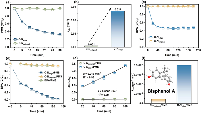
The PMS dissociation catalyzed by C—Nedge and C—Noriginal was initially evaluated. As shown in Fig. 2a, C—Nedge could catalyze about 70% of PMS decomposition within 30 min, while C—Noriginal had almost no catalytic effect on PMS. The apparent rate constant (kobs, min−1) of PMS decomposition catalyzed by C—Nedge was 0.027 min−1, which was 27-fold higher than that of C—Noriginal (0.001 min−1) (Fig. 2b and Fig. S6 in Supporting information), indicating its superior catalytic activity. When BPA was added to the PMS solution, the concentration of PMS did not decrease (Fig. S7 in Supporting information), indicating that BPA had no effect on the dissociation of PMS. Then, the pollutant removal performance of the catalytic system was investigated by selecting BPA as a representative refractory pollutant. Since C—Nedge had a high specific surface area, adsorption experiments were required to determine the adsorption equilibrium time and exclude the effect of adsorption on BPA degradation. As shown in Fig. 2c, catalyst reached adsorption equilibrium after about 40 min and C—Nedge adsorbed about 51% of BPA. Degradation experiments (Fig. 2d) showed that both PMS and C—Noriginal/PMS systems were unable to oxidize BPA and the pH of the three reaction systems remained stable (Fig. S8 in Supporting information). After 160 min of reaction, almost all BPA was degraded in the C—Nedge/PMS system. The results of the degradation curve fitting indicated that the BPA removal followed pseudo first-order kinetics (Fig. 2e), and the reaction rate constants were calculated to be 018 min−1 and 0.0003 min−1 for C—Nedge/PMS and C—Noriginal/PMS, respectively. The apparent rate constants obtained from the degradation experiments were further normalized by the specific surface area of the catalysts to obtain specific rate constants (kSA, g m−2 min−1) [23], to compare the catalytic activity of the two catalysts. The normalized apparent rate constant for C—Nedge were 8 times higher than C—Noriginal (Fig. 2f), indicating its well catalytic degradation performance. What's more, compared with the previously reported references, C—Nedge also had high catalytic performance (Table S3 in Supporting information).
Figure 2
Figure 2.
Catalytic degradation performance evaluation. (a) PMS decomposition catalyzed by the C—Nedge and C—Noriginal and (b) the related decomposition rate constants. (c) Adsorption and (d) degradation curves of BPA by different reaction systems. (e) Pesudo-first-order kinetics fitting curve of BPA degradation. (f) Relationship between the specific activities (kSA) of different catalysts. Reaction conditions: [catalysts] = 0.05 g/L, [BPA] = 50 mg/L, [PMS] = 2 mmol/L, pH 7.0.
In order to explore the mechanism of activating PMS to degrade BPA by C—Nedge/PMS, different quenchers were selected and added, where EtOH was used to both quench ·OH and SO4•− while TBA was for quenching ·OH [24], and L-histidine was for quenching 1O2 [25]. The quenching results (Fig. 3a) showed that both EtOH and TBA did not inhibit BPA degradation in the C—Nedge/PMS system, while L-histidine retarded the degradation rate of BPA, indicating that there may be 1O2 in this system. EPR spectra illustrated that the signal of DMPOX appear (Fig. S9 in Supporting information) when DMPO was added, but not the characteristic signal of 1:2:1:2:1. The appearance of the DMPOX signal may be due to the strong oxidizing nature of the C—Nedge surface. TEMP can specifically capture 1O2, producing TEMP-1O2 with a 1:1:1 triplet state characteristic peak [26]. As shown in Fig. 3b, a typical 1:1:1 triplet state characteristic peak was observed after mixing C—Nedge with PMS, demonstrating the possible production of 1O2. Since 1O2 can prolong the life in D2O [27], the degradation of pollutants in H2O and D2O by C—Nedge/PMS system was compared, which can effectively prove the role of 1O2 in the reaction system. As shown in Fig. 3c, the degradation of BPA was not accelerated in D2O, which contradicts the previous findings on 1O2. Although EPR and quenching experimental results might indicate the possible 1O2 dominated oxidation mechanism, the recent up-to-date studies provide the opposite interpretation. First of all, it was revealed that common oxidants such as PMS and peracetic acid would direct oxidize TEMP into TEMPO, causing false positive results [28]. Secondly, the high surface area and porosity of C—Nedge provides abundant adsorption sites for L-histidine, which might lead to the activate sites coverage and declined catalytic activity. A similar result was also obtained in a recent study by Zhou et al. [29]. Consequently, we excluded the possible 1O2 generation in this study, while another non-radical oxidation pathway, i.e., electron transfer, might exist [30,31].
Figure 3
Figure 3.
Reactive oxidative species identification. (a) Effect of EtOH, TBA and L-histidine on BPA degradation in the C—Nedge/PMS systems. (b) TEMP-trapped 1O2 EPR spectra. (c) BPA degradation performance by exchaning solvent from H2O to D2O. (d) In situ FTIR spectra changes after mixing C—Nedge with PMS. (e) Amperometric I-t curve. (f) EIS of catalysts. (g) Proposed pathways of BPA degradation in C—Nedge/PMS system. Reaction conditions: [catalysts] = 0.05 g/L, [BPA] = 50 mg/L, [PMS] = 2 mmol/L, pH 7.0, [EtOH] = [TBA] = 200 mmol/L, [L-histidine] = 20 mmol/L, [DMPO] = [TEMP] = 60 mmol/L.
We next verified the existence of electron transfer mechanism in the C—Nedge/PMS system, and the in situ infrared spectroscopy test was carried out. As shown in Fig. 3d, the infrared spectrum of PMS had an obvious vibration peak at about 1100 cm−1, representing the vibration of O=S=O structure in PMS [32]. When PMS and catalyst are added together, the peak position of O=S=O in PMS had a blue shift of about 7 cm−1, to the peak position of 1107 cm−1. It represents that PMS was bound to the catalyst, which was one of the evidence of electron transfer in the degradation of BPA by C—Nedge/PMS system [33]. In addition, the constant potential time-to-current response test that had been widely adopted as an effective electrochemical method to demonstrate the presence of electron transfer [34] was conducted. As shown in Fig. 3e, adding BPA stimulated a significant increase in current output. This showed that BPA was first absorbed by C—Nedge catalyst, and then directly provided electrons to PMS, which is used as the electronic channel for oxidation [35]. Furthermore, we set up a galvanic oxidation reactor [36,37], so BPA can only be oxidized via ETP (Fig. S10 in Supporting information). After respectively adding BPA and PMS into separate two half-cells, a stable electric current could be observed. This proved that electrons can be transferred from BPA to PMS through conducting C—Nedge, resulting in the decomposition of PMS and the simultaneous degradation of BPA.
A good conductivity of catalyst is the prerequisites for its good electron transfer ability. Therefore, the charge transfer resistance (Rct) of the catalyst was measured by electrochemical impedance spectroscopy [38], and the results were shown in Fig. 3f and Table S4 (Supporting information). Compared with C—Noriginal (Rct = 27, 380 Ω), C—Nedge (Rct = 2398 Ω) had a smaller charge transfer resistance, which indicated that the addition of potassium carbonate in the carbonization process can significantly increasing the conductivity of the catalyst, and the good conductivity was also the premise for the strong electron transfer ability of C—Nedge in the process of activating PMS to degrade BPA [39].
In order to understand the possible degradation pathways of BPA, the intermediates were analyzed by HPLC-MS/MS and seven intermediates were identified (Table S5 and Fig. S11 in Supporting information). Based on the identified intermediates and previous studies [40–44], a possible degradation pathway for BPA was proposed (Fig. 3g). Firstly, in pathway Ⅰ, the C—C bond between the benzene rings was broken to form P2 [43] and direct electron transfer pathways induced the subsequent formation of P3 and P4 [41]. Next, in pathway Ⅱ, the C—O bond bound to the benzene ring was cleaved, and then the hydroxyl group separated from the BPA, leading to the formation of P5 [43]. P6 and P7 may be further produced by breaking the C single bond C bond connecting the two benzene rings [40].
Catalytic stability is very important in the catalytic system [45], recycling tests were conducted to assess the stability and reusability of C—Nedge for the PMS-based degradation system. The result showed that the degradation rate of BPA in the C—Nedge/PMS system was still as high as 84% after three times of recycling (Fig. 4a). Metal center was reported to be easily deactivated and then induced the catalytic performance decline [45]. However, in this work, no metal sites were present in the C—Nedge. Herein, it was deduced that the decrease in the catalytic performance of the C—Nedge might be due to the masking of the active sites by the formed intermediates. To verity the above assumption, the C—Nedge after 3-cycle of use was collected and treated by ethanol rinsing or pyrolysis. Either ethanol washing or pyrolysis disposal was efficient in recovering catalytic activity of C—Nedge (Fig. S12 in Supporting information). In order to evaluate the feasibility of applying C—Nedge into different water bodies treatment, this study selected tap water, Yuhangtang River water and secondary effluent of sewage treatment plant as representative water bodies to conduct BPA degradation experiments. It can be seen from Fig. 4b that the C—Nedge/PMS system had a high removal rate under the condition of different water body. Consistently, SEM image (Fig. S13 in Supporting information) and XRD pattern (Fig. S14 in Supporting information) of C—Nedge catalyst before and after degradation experiment showed negligible changes. The C—Nedge/PMS system not only showed good removal effect on BPA, but also had good degradation effect on other pollutants. As shown in Fig. 4c, the C—Nedge/PMS system can achieve rapid degradation of DCF, Triclosan and 2, 4, 6-TCP. Considering that the wastewater is rich in inorganic anions and natural organic matter, the effects of some inorganic anions (e.g., Cl−, HCO3−, H2PO4−) and HA on the degradation of BPA by C—Nedge catalyzed PMS were evaluated (Fig. 4d). These composite substrates had no significant effect on the degradation of BPA, indicating that C—Nedge may be a potential environmental recovery catalyst.
Figure 4
Figure 4.
Feasibility of applying the as-prepared biochar for actual wastewater remediation. (a) Recovery and reuse ability of C—Nedge. (b) The degradation curves of BPA in different water bodies (the inset figure is Pseudo-first-order kinetics). (c) Feasibility of removing other refractory organic pollutants by C—Nedge/PMS system. (d) Interference by background dissolved solutes. Reaction conditions: [C—Nedge] = 0.05 g/L, [DCF] = [2, 4, 6-TCP] = [Triclosan] = 50 mg/L, pH 7.0, [PMS] = 2 mmol/L, [Cl−] = [HCO3−] = [H2PO4−] = 2 mmol/L, [HA] = 2 mg/L.
In this work, biochar self-doped with edge graphitic N was successfully fabricated via one-pot co-pyrolysis of chitosan and potassium carbonate. Under the set test conditions, a very small amount of C—Nedge (0.05 g/L) can catalyze PMS decomposition to degrade 98% of BPA (50 mg/L) in 140 min. After three times of recycling, the degradation efficiency of BPA still reached 84%, indicating its good reuse ability. Multiple characterization and analytical methods verified that electron transfer mechanism was the dominated pathway for BPA degradation and the edge graphitic N with strong electron transfer ability was identified as the responsible active site. Also, the C—Nedge/PMS catalytic oxidation system was efficient to other refractory pollutants removal, and was not interfered by inorganic anions in water, indicating that C—Nedge may be a stable and workable catalyst for remediating wastewater under environmental conditions. The results of this work are valuable for in-depth understanding the N-doping configuration on activating PMS for wastewater remediation by biochar.
Declaration of competing interest
The authors declare that they have no known competing financial interests or personal relationships that could have appeared to influence the work reported in this paper.
Acknowledgments
The authors wish to thank the National Natural Science Foundation of China (No. 51908172) and "Pioneer" and "Leading Goose" R & D Program of Zhejiang (No. 2023C03149) for the financial support of this work.
Supplementary materials
Supplementary material associated with this article can be found, in the online version, at doi:10.1016/j.cclet.2023.109437.
Figure 1
Catalyst structure property characterization. (a) The SEM image of C—Nedge; (b) Raman spectra of the catalysts; (c) N 1s XPS spectrum of C—Nedge; TG-FTIR spectrum changes during pyrolysis of (d) chitosan and (e) chitosan plus K2CO3.
Figure 2
Catalytic degradation performance evaluation. (a) PMS decomposition catalyzed by the C—Nedge and C—Noriginal and (b) the related decomposition rate constants. (c) Adsorption and (d) degradation curves of BPA by different reaction systems. (e) Pesudo-first-order kinetics fitting curve of BPA degradation. (f) Relationship between the specific activities (kSA) of different catalysts. Reaction conditions: [catalysts] = 0.05 g/L, [BPA] = 50 mg/L, [PMS] = 2 mmol/L, pH 7.0.


 DownLoad:


 下载:
下载:


 下载:
下载:
