Citation:
Bo Yang, Pu-An Lin, Tingwei Zhou, Xiaojia Zheng, Bing Cai, Wen-Hua Zhang. Facile surface regulation for highly efficient and thermally stable perovskite solar cells via chlormequat chloride[J]. Chinese Chemical Letters,
2024, 35(10): 109425.
doi:
10.1016/j.cclet.2023.109425
Facile surface regulation for highly efficient and thermally stable perovskite solar cells via chlormequat chloride
English
Facile surface regulation for highly efficient and thermally stable perovskite solar cells via chlormequat chloride
Received Date:
28 July 2023 Accepted Date:
19 December 2023 Revised Date:
18 November 2023 Available Online:
15 October 2024
Abstract:
Defects at the surface and grain boundaries of the perovskite films are extremely detrimental to both the efficiency and stability of perovskite solar cells (PSCs). Herein, a simple and stable quaternary ammonium halide, named chlormequat chloride (i.e., chlorinated choline chloride, CCC), is introduced to regulate the upper surface chemical environment of perovskite films. The anion (Cl−) and cation [ClCH2CH2N(CH3)3]+ in CCC could effectively self-search and passivate positively and negatively charged ionic defects in perovskites, respectively, which contributes to inhibited nonradiative recombination and reduced energy loss in PSCs. As a result, the champion power conversion efficiency (PCE) of PSCs can be significantly enhanced from 22.82% to 24.07%. Moreover, the unencapsulated device with CCC modification retains 92.0% of its original PCE even subject to thermal aging at 85 ℃ for 2496 h. This work provides guidance for the rational design of functional molecules as defect passivators in PSCs, which is beneficial for the improvements in both device performance and stability.
Based on the unique structure and ionic nature, organic-inorganic halide perovskites exhibit many excellent photoelectric properties, such as high light absorption coefficient (105 cm−1), long charge carrier diffusion lengths (> 1 µm) [1,2], and low cost preparation methods [3-5]. To date, the certified power conversion efficiency (PCE) of single-junction perovskite solar cells (PSCs) has boosted to 26.14%, close to the record of crystalline silicon cells (26.81%), making PSCs the most promising new generation of photovoltaic technology [6]. This rapid blossom could derive from effectively regulating crystallization process of perovskite films [7,8], exploring innovate carrier charge layers [9-11], and discovering unique interfacial materials [12,13]. Similar to other polycrystalline and thin-film photovoltaic cells, inevitable and detrimental charged defects (e.g., MA/FA vacancies and I vacancies) are often generated at grain boundaries (GBs) and surfaces of perovskites during the thermal annealing or illumination process owing to the low formation energy and small migration activation energy of perovskites [14-18], which is an important factor limiting the performance improvement of PSCs. Moreover, these defects can initiate the degradation of perovskite films induced by the infiltrated water/oxygen. Therefore, there is an urgent need to develop efficient techniques to passivate the defects on the surfaces and GBs of perovskite films to further improve device performance and operational life.
Post-treatment is a simple and effective method that can passivate the surface of perovskites by precisely adjusting the reaction conditions. At present, a large number of passivating agents have been reported, including polymers, inorganic salts, and organic salts, etc. [19-21]. Among them, alkyl ammonium halide (RNH3X), such as PEAI, DABr and PMABr, could effectively passivate positively and negatively charged ionic defects by X− anion and (RNH3)+ cation, respectively [22-24]. Especially, considering the higher binding energy of Cl-Pb than that of I-Pb and the longer carrier life of Cl-doped perovskites [25-27], using Cl− anion with RNH3+ as passivation agent can not only improve the stability of perovskite but also improve the charge transfer efficiency in perovskites [28]. However, due to the deprotonation of RNH3+, Cl− anion is easily removed along with the hydrogen atoms on the amino group [29]. Fortunately, quaternary ammonium chloride (R4NCl) without any hydrogen atom on the amino group does not cause deprotonation, so the Cl− anion can be stabilized. Among various quaternary ammonium halides (Table S1 in Supporting information), choline chloride [CC, HOCH2CH2N+(CH3)3·Cl−] is the earliest and most used to passivate the defects on the surface of perovskites and greatly improve the open-circuit voltage (VOC) and PCEs of the PSCs [12]. However, the alcohol hydroxyl group on choline chloride, which is prone to react with hydrogen iodide released from the reversible decomposition of perovskites, may accelerate the decomposition of perovskites (Fig. S1 in Supporting information). Recently, Seok et al. post-treated α-FAPbI3 films with sequentially coated acetylcholine chloride [ACCl, CH3COOCH2CH2N+(CH3)3·Cl−] and PEAI, delivering a champion device efficiency of 24.53% with enhanced thermal and light stability [30]. However, it is still highly desirable to explore the passivation mechanism of quaternary ammonium salt in depth, and explore novel functional molecules to passivate perovskites effectively without sacrificing their stability.
In this study, we introduce a simple and stable quaternary ammonium halide without hydroxyl group, named chlormequat chloride (i.e., chlorinated choline chloride, CCC, a plant growth retardant), for the post-treatment of perovskite films. It was found that the CCC mainly distributed on the upper surface of the perovskite films and slightly percolated into the GBs of the shallow perovskite layer, forming a gradient descent distribution. A reasonable regulatory mechanism for CCC modified perovskite films could be proposed: The positively charged quaternary ammonium cation in CCC can anchor the MA+ or FA+ vacancies and generate the electrostatic interactions with I− of perovskites [12,31,32]. The negatively charged Cl− in CCC may occupy the I− vacancies to form the stronger Pb-Cl bonding than the Pb-I bonding [25,26,33]. In addition, a more p-type surface of perovskite films could be constructed owing to the downshifted Fermi level [34], resulting in the decreased barriers of hole extraction and transportation. As a result, the density of defect states is greatly reduced and the non-radiative recombination process is significantly inhibited [35]. With CCC treatment, the champion PCE of PSCs was boosted from 22.82% to 24.07%. This strategy can also enhance the stability of PSCs: Almost no efficiency loss after 3200 h of storage at room temperature, and less than 10% loss after 2496 h thermal aging at 85 ℃. These results highlight the importance of functional molecular design for perovskite passivation, driving further improvements in the performance and stability of perovskite devices.
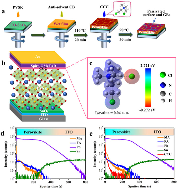
The detailed process to fabricate the CCC-modified perovskite films was illustrated in Fig. 1a. The pristine FA-MA-Cs perovskite films were prepared by an anti-solvent spin-coating method. Surface treatment was performed by spin-coating CCC/isopropanol solution followed with post annealing at 90℃ for 30 min. The PSCs with the architecture (Fig. 1b) of glass/ITO/SnO2/Cs0.05(FA0.98MA0.02)0.95Pb(I0.98Br0.02)3/spiro-OMeTAD/Au were fabricated to investigate the impact of CCC treatment. During the cell fabrication process, many detrimental negative and positive charged defects are inevitably produced at the surface or GBs of perovskite films, which are detrimental to PCEs and stability of PSCs [36,37]. To address this issue, CCC with separated anions and cations, a chemical formula of ClCH2CH2N+(CH3)3·Cl−, was introduced as an interface modification layer. The electrostatic potential (ESP) of CCC in Fig. 1c shows that the quaternary ammonium cation exhibits positive ESP (blue) and the Cl− anion displays negative EPS (red), which could self-seek and then passivate the charged defects of opposites that were inhomogeneously distributed at the perovskite films. To observe the possible changes of the interface between perovskite and HTLs, the cross-section SEM images of the PSCs and perovskite films without and with CCC modification were checked. As shown in Fig. S2 (Supporting information), compared with smooth surface of the pristine film, the CCC modified perovskite film has some small particles on its surface (blue circles), indicating that the interface between perovskite and HTLs was modified by the CCC, which is accordance with the top-view SEM images in Figs. 2a and b. To investigate the distribution of CCC in perovskite films, the time-of-flight secondary-ion mass spectrometry (TOF-SIMS) was measured to explore the depth profiles of positive compositions in the perovskite films with or without CCC modification (Figs. 1d and e, Fig. S3 in Supporting information). Compared with the control sample, the intensity of quaternary ammonium cation from CCC appeared a high value at the surface and then a gradient decline with depth in the target film, implying that CCC mainly enriched on the top surface of perovskite film and slightly penetrated into the shallow perovskite layer. Owing to the large molecular size, the penetrated CCC could only located at GBs [12].
Figure 1
Figure 1.
(a) Schematic diagram of preparation process of CCC treated perovskite layers. (b) Device structure diagram of a n-i-p structured PSC. (c) The electrostatic potential diagram of CCC. TOF-SIMS depth profiles of the (d) control and (e) CCC modified perovskite films.
Figure 2.
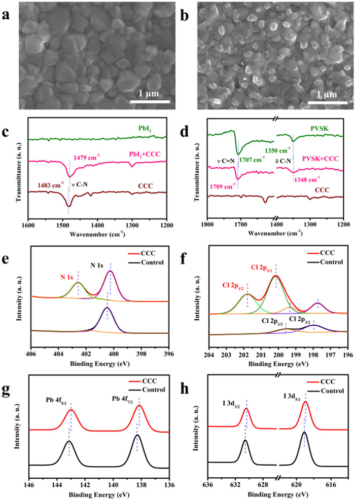
Top-view SEM images of the (a) control and (b) CCC modified perovskite films. (c) FTIR spectra of PbI2, CCC and PbI2 mixed CCC samples. (d) FTIR spectra of CCC, perovskite and CCC modified perovskite. High resolution XPS spectra of (e) N 1s, (f) Cl 2p, (g) Pb 4f, and (h) I 3d for the perovskite films with and without CCC modification.
The X-ray diffraction (XRD) patterns for the control and target perovskite films exhibited the same diffraction positions and full width at half maximum (FWHM) (Fig. S4 in Supporting information) without non-perovskite, 2D-perovskite or PbI2 phases [19,21,38], suggesting that CCC is not incorporated into the perovskite crystal lattice [1,30,38], and should work as the surface passivator. The scanning electron microscope (SEM) images in Fig. 2a show that the substrate was fully covered by perovskite grains without any pin holes. The statistical average crystal size was about 325 nm (Fig. S5 in Supporting information). After the post-treatment, CCC was evenly distributed on the surface of the perovskite film especially at the grain boundaries (Fig. 2b), indicating that the undesired defects located at GBs could be passivated in the CCC modified perovskite films [31]. The atomic force microscopy (AFM) images displayed that the root mean square (RMS) of the perovskite films increased from 27.5 nm to 35.6 nm upon CCC treatment (Fig. S6 in Supporting information), which was in good agreement with the previous SEM results. The Fourier transform infrared (FTIR) spectroscopy was used for confirming the interaction between the CCC and PbI2/perovskites. As shown in Fig. 2c, the stretching vibration peak of C—N in CCC shifted from 1483 cm−1 to 1479 cm−1 in CCC-PbI2 mixed samples, which could be attributed to the electrostatic interaction between quaternary ammonium cation in CCC and I− anion [39,40]. The bending vibration of C—N located at 1350 cm−1 in the control perovskite film was slightly shifted to 1348 cm−1 in the CCC modified one and the stretching vibration peak of C—Cl in CCC shifted from 781 cm−1 to 770 cm−1 in CCC-FAI mixed samples, indicating the formation of hydrogen bonds N-H···Cl between the amine groups of perovskites and CCC molecules (Fig. 2d and Fig. S7 in Supporting information) [41-45]. The X-ray photoelectron spectroscopy (XPS) was adopted to further elucidate the interaction between the CCC and perovskite. As shown in Fig. 2e, compared with the control perovskite film, a new peak located at 402.56 eV appeared, confirming the presence of CCC in the target perovskite film. The N 1s peak at 400.47 eV from FA+ slightly shifted to a lower binding energy located at 400.23 eV, which could be ascribed to the interaction between Cl group in CCC and FA+ through hydrogen or ionic bonding [1]. Two new peaks located at 201.79 and 200.16 eV were only detected in the target perovskite film, which belonged to Cl 2p1/2 and Cl 2p3/2 in CCC, respectively (Fig. 2f and Fig. S8 in Supporting information) [46]. And the residual Cl in the target perovskite film appeared a slight shift to a lower binding energy than that of the control one, which might be attributed to the interaction between quaternary ammonium cation in CCC and Cl− through ionic bonding. As displayed in Fig. 2g, the Pb 4f5/2 and 4f7/2 peaks simultaneously downshifted to lower binding energies from 143.14 to 138.28 eV to 142.99 and 138.14 eV after CCC modification, respectively, which could be attributed to the interaction between undercoordinated Pb2+ and electron-rich Cl group in CCC [33,47]. The previous literatures represent that this downshift trend for Pb 4f peaks may originate from the surface p-type doping [48,49]. As illustrated in Fig. 2h, a similar trend to a lower binding energy was observed for I 3d peaks from 630.55 and 619.08 eV to 630.42 and 618.95 eV after CCC modification [1,46,50], respectively, which could be ascribed to the electrostatic interaction between quaternary ammonium cation in CCC and I− anion through ionic bonding.
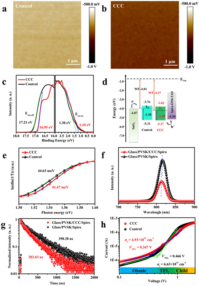
To further confirm that a more p-type perovskite surface was obtained after the CCC modification, the Kelvin probe force microscopy (KPFM) was performed to acquire the surface electrostatic potential distribution of perovskite films. The average contact potential difference (CPD) of the control and target perovskite films were about −603 and −745 mV, respectively (Figs. 3a and b, Fig. S9 in Supporting information), which signified the Fermi level (EF) downshift close to the valence band maximum of perovskites after CCC modification [34]. The band gap of perovskite films with or without CCC treatment was about 1.55 eV by ultraviolet-visible absorption (UV–vis) measurements (Fig. S10 in Supporting information). Moreover, the ultraviolet photoelectron spectroscopy (UPS) was adopted to evaluate the energy band structure of perovskite films. As shown in Figs. 3c and d, the perovskite films presented a downshift of the EF from −4.01 to −4.27 eV after the CCC modification, which was consistent with the XPS and KPFM results. This indicated that a more p-type perovskite surface was gained and the hole extraction ability from the perovskite to the hole transport layer (HTL) was also promoted [51]. In addition, as shown in Fig. 3e, the Urbach energy of the control perovskite film was 44.63 meV, higher than that of the target perovskite film at 41.47 meV, indicating a higher degree of disorder in the structure of control perovskite films and thus led to more serious carrier recombination [52]. To probe into the charge-carrier dynamics behaviors in perovskite films, steady state photoluminescence (PL) and time-resolved photoluminescence (TRPL) spectroscopies were carried out. The target film exhibited a stronger PL intensity than that of the control perovskite film without a quenching layer, which implied an effective defects passivation after CCC modification (Fig. S11 in Supporting information). As illustrated in Fig. 3f, when a quenching layer (spiro-OMeTAD) was introduced, the target film displayed a faster PL quenching signal than that of the control perovskite film, indicating a more efficient carrier extraction at the interface of perovskite/quenching layer after CCC treatment. In addition, the PL emission peak of perovskite films was shifted from 815 nm to 813 nm after CCC modification, demonstrating reduced defects by effective passivation [53,54]. A bi-exponential function with fast and slow components was used for fitting the TRPL decay curves (Eq. 1):
(1)
Figure 3
Figure 3.
(a, b) KPFM images and (c) UPS spectra of the control and CCC modified perovskite films. (d) The corresponding energy band structure diagram of PSCs. (e) Urbach energy, (f) PL and (g) TRPL of the perovskite films with and without CCC modification. (h) Dark I-V curves of devices based on the configuration of ITO/NiOx/perovskite/spiro-OMeTAD/Au with and without CCC modification.
where the τ1 interpreted the fast decay process caused by bimolecular recombination of photo-generated free carriers, and the τ2 represented the slow decay process attributed to trap-assisted recombination [12]. B is a constant for the baseline offset. A1 and A2 are constants accounting for the contributions of the fast and slow components, respectively [55]. The τ2 sharply decreased from 406.48 ns to 291.26 ns, but the τ1 only changed from 30.79 ns to 22.98 ns after CCC treatment, implying that the CCC modification mainly impacted the slow decay process. The average PL lifetime (τave) can be calculated by Eq. 2:
(2)
As shown in Fig. 3g, the τave reduced from 398.38 ns to 282.63 ns after CCC modification, indicating that the nonradiative recombination was effectively suppressed and the carrier charge extraction was further promoted [56]. To evaluate the trap-state in the perovskite films with or without CCC modification, the space-charge-limited current (SCLC) method was performed. The trap density (nt) can be determined by Eq. 3 [57]:
(3)
where VTFL is the trap-filled limit voltage, e is the elementary charge (1.6 × 10⁻¹⁹C), ε0 is the vacuum permittivity (8.85 × 10⁻¹² F/m), ε is the relative dielectric constant of the perovskite (46.9) [58], L is the thickness of the perovskite film (~604 nm). As shown in Fig. 3h, the VTFL reduced from 0.466 V to 0.347 V, corresponding with the density of hole traps decreased from 6.63 × 1015 cm−3 to 4.93 × 1015 cm−3 after CCC modification. Lower trap density could achieve higher VOC and FF in the passivated device.
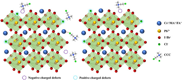
According to the above results, a regulatory mechanism for CCC modified perovskite films could be reasonably proposed as illustrated in Fig. 4. Most of the coated CCC are concentrated on the upper surface of perovskite film, and a small amount penetrate into the shallow layer of perovskite. Due to its large molecular size, the penetrated CCC could only located in GBs, and its concentration is distributed in a gradient decline with depth. During the thermal annealing process of perovskite films, the evaporation of organic components and halogens will inevitably lead to many unexpected negatively and positively charged vacancies on the surface and GBs of perovskite films, which could be compensated or passivated by the post-treatment with CCC. Quaternary ammonium ions in CCC can anchor MA+ or FA+ vacancies and interact electrostatically with I−. Since the Pb-Cl bond is stronger than the Pb-I, the Cl− in CCC can occupy the I− vacancy and exhibit a significant passivation effect. In addition, hydrogen bond N-H···Cl was formed between the perovskite amine group and CCC, which further enhanced the passivation effect and stability of the modified perovskite film. Furthermore, the decrease of CPD and EF makes the surface of CCC modified perovskite more p-type, which is conducive to the rapid extraction and transportation of holes. As a result, CCC can effectively passivate defects on the surfaces and GBs of perovskites, which is expected to reduce energy loss, improve device performance, and increase long-term stability.
Figure 4
Figure 4.
The proposed regulatory mechanism of perovskite films with CCC passivated surface and GBs.
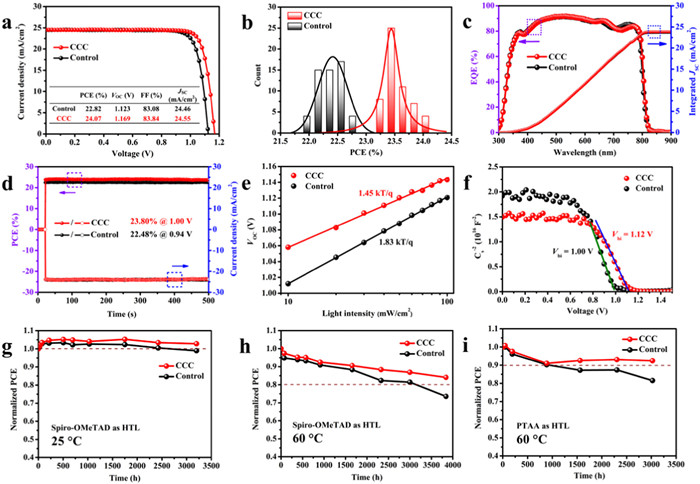
To optimize the photovoltaic performance, 20 individual cells for each CCC concentration (0–2 mg/mL) were prepared to explore the optimized condition (Fig. S12 in Supporting information), whose corresponding champion photovoltaic parameters were listed in Table S2 (Supporting information). As illustrated in Fig. 5a, the best performing device with 1.5 mg/mL CCC modification delivered a high PCE of 24.07% with VOC of 1.169 V, JSC (short circuit current density) of 24.55 mA/cm2 and FF (fill factor) of 83.84%, whereas the control device only gave a PCE of 22.82% with VOC of 1.123 V, JSC of 24.46 mA/cm2 and FF of 83.08%. The corresponding photovoltaic parameters of statistical 55 individual cells were represented (Fig. 5b, Fig. S13, Tables S3 and S4 in Supporting information), confirming the outstanding batch-to-batch reproducibility. Compared with the slight improvement JSC, the significant enhance VOC and FF could be attributed to reduced energy loss and improved carrier extraction/transportation at the interface between perovskite and hole transportation layers [59]. The highest value of VOC reached 1.169 V, and the corresponding voltage loss (bandgap - VOC) was only 0.381 V [60], which was comparable with silicon solar cells (0.38 V) [61]. The current density-voltage (J-V) curves and parameters under reverse and forward scan directions were presented in Fig. S14 and Table S5 (Supporting information), which gave a lower hysteresis after CCC modification owing to possibly promote charge transportation and hinder defects migration [31,62]. To assess the rationality of JSC values from the J-V curves, the external quantum efficiency (EQE) was measured. As shown in Fig. 5c, the integrated photocurrent density of the CCC modified cell was calculated to be 23.86 mA/cm2, a slightly higher than that of the control one at 23.72 mA/cm2, which was in agreement with the results from J-V curves (~3% deviation). To acquire the exact and real output performance of the devices, the maximum output power point tracking (MPPT) was further performed. As shown in Fig. 5d, after about 500 s of testing, the CCC modified device stabilized at 23.80% (Vmpp = 1.00 V), higher than that of the control device at 22.48% (Vmpp = 0.94 V).
Figure 5
Figure 5.
Photovoltaic performance of PSCs with and without CCC modification: (a) The champion J-V curves. (b) PCEs statistics from 55 individual devices. (c) EQE curves and the corresponding integrated JSC, and (d) stabilized output PCEs and JSC of the devices based on the above conditions. (e) VOCvs. light intensity, (f) Mott-Schottky fitting to the capacitance-voltage (C−2-V) plots of the PSCs with and without CCC modification. (g–i) Long-term stability tests of the unsealed PSCs stored in a N2-filled glovebox under dark. Each point represented an average of five devices.
To furthermore verify the carrier charge recombination behaviors, the J-V curves of PSCs were also measured under different incident light intensity (0.1–1 sun). The light intensity-dependent JSC variation exhibited the same slope of 0.96 for PSCs with or without CCC modification (Fig. S15 in Supporting information), meaning the negligible bimolecular recombination and the predominant trap-assisted recombination [63]. The ideality factor (n) is often applied to depict the recombination type in PSCs. Typically, the n gets closer to 1, indicating that more radiative recombination occurs in the devices. Inversely, the n gets closer to 2, interpreting that more nonradiative recombination become domination owing to the presence of undesired traps in imperfect devices [64]. As shown in Fig. 5e, the light intensity-dependent VOC variation for the target device exhibited the n of 1.45 smaller than that of the control device at 1.83, meaning that the defects-induced recombination was effectively suppressed in the CCC modified devices [65,66]. As shown in Fig. S16 (Supporting information), the dark J-V curve of the CCC modified PSCs showed a significantly lower leakage current compared to the control one, corresponding to the trap-filled limit voltage and ideal factor results [67,68]. To better clarify carrier charge extraction behaviors, the built-in potential (Vbi) of the PSCs was performed by the Mott-Schottky (M-S) measurement [69]. As shown in Fig. 5f, the Vbi of the target device was 1.12 V, observably higher than that of the control device at 1.00 V, proving an increased driving force for the separation of photogenerated carriers and suppressed nonradiative recombination. To elucidate the interfacial carrier charge transfer and transport kinetics behaviors, the electrochemical impedance spectroscopy (EIS) of control and target PSCs was measured at an applied bias voltage of 0 V under dark. As illustrated in Fig. S17 (Supporting information), the given equivalent circuit was empirically fitted with the Nyquist plots for both cells to obtain the charge-transport resistance (Rtr) and recombination resistance (Rrec) [70], whose corresponding values were summarized in Table S6 (Supporting information). The target device demonstrated a lower Rtr and a higher Rrec than those of the control one, which manifested a faster carrier charge transfer and a slower recombination process and thus acquired higher VOC and FF values after CCC modification.
Reliable stability is a prerequisite for the commercialization of PSCs. To explore the self-stability of our devices, highly efficient PSCs in Fig. 5b (with spiro-OMeTAD as HTL) were stored in a N2-filled glovebox at room temperature under dark without encapsulation. As shown in Fig. 5g and Fig. S18a (Supporting information), after 3200 h ambient storage, the CCC modified device retained 102.8% of its original efficiency, whereas the control device remained 98.9% of its initial efficiency. XRD, UV–vis absorption and SEM were conducted to study the aged perovskite films in Fig. S19 (Supporting information). Although the morphology in SEM images and UV–vis absorption of both the films did not change significantly with aging, there was a strong signal of δ-FAPbI3 appeared in the XRD pattern of the control device, while the CCC modified sample remained almost unchanged, indicating that the phase stability of perovskites can be significantly enhanced by CCC modification. In order to investigate the resistance of our device to thermal stress, the PSCs with and without CCC treatment were placed on a hotplate at 60 ℃. As shown in Fig. 5h and Fig. S18b (Supporting information), after 3840 h thermal aging, the CCC modified device retained 84.0% of its original efficiency, more than that of the control one (73.5%). In addition, to exclude the effect of unstable spiro-OMeTAD on the device performance, PTAA was also used instead of spiro-OMeTAD to study the thermostability of PSCs [71,72]. As shown in Fig. 5i and Fig. S18c (Supporting information), after 3024 h thermal aging at 60 ℃, CCC modified device remained a 92.4% of its original efficiency, more than that of the control one (81.5%). The XRD patterns of control perovskite films exhibited stronger signals of δ-FAPbI3 and PbI2 phases than that of the CCC modified perovskite films during thermal tests. But UV–vis absorption of both the films did not change obviously, which could be ascribed to the amount of the perovskite main phase more than that of the decomposition products to a large extent. Moreover, the SEM images of control perovskite films displayed much more holes on the surface compared with the target perovskite films (Figs. S20 and S21 in Supporting information). These results indicate that the decomposition of perovskite under thermal aging can be significantly inhibited by CCC modification. The CCC bound to GBs/surface terminal groups could contribute to the enhanced stability of perovskites by strengthening binding forces and decreasing the surface energy of perovskite films [30,73]. Our results manifested that, due to the passivation effect of CCC on different defects, the stability of PSCs can be significantly improved along with the efficiency. Furthermore, in order to investigate the influence of different functional groups on the stability of the perovskite films, we also conducted accelerated aging tests at 100 ℃ for pristine and passivated perovskite films by CC or CCC treatment. As shown in the XRD pattern of Fig. S22 (Supporting information), after 4 days of thermal aging, obvious PbI2 phase appeared in the unmodified perovskite film, while the main peak (001) of perovskites at 13.99 was significantly reduced. Compared with the aging perovskite films, XRD pattern of one with CC treatment changed only a little. Thus, it is speculated that the alcohol hydroxyl group on CC has the effect of accelerating the decomposition of perovskites (Fig. S1 in Supporting information), which counteracts the effect of enhancing stability due to defect passivation by CC. Surprisingly, after CCC modification, the PbI2 phase was significantly weakened and the perovskite phase also retained a strong signal, demonstrating that CCC without hydroxyl group can significantly enhance the thermal stability of perovskites. To confirm this, PSCs with or without passivators were heated at a high temperature of 85 ℃ for 2496 h. As shown in Fig. S23a (Supporting information), the control device only retained 65.2% of its initial efficiency, while CC and CCC modified devices maintained 83.3% and 92.0% of their initial efficiency, respectively, demonstrating that CCC modification is superior to CC in improving device stability. The XRD patterns of the CCC modified perovskite films indeed presented weaker signals of δ-FAPbI3 and PbI2 phases than that of other perovskite films after thermal aging, and UV–vis absorption of films did not change apparently (Figs. S23b and c in Supporting information). Moreover, the SEM images of the CCC modified perovskite films hardly did not display holes on the surface compared with the control and CC modified films (Fig. S24 in Supporting information). To confirm the CCC as an effective and universal passivator for different cells, we fabricated the perovskite films via sequential deposition and then adopted the CCC as a passivator on their surface. In accordance with the PSCs prepared by one-step spin-coating method, we also got a positive result in sequential deposited PSCs as shown in Fig. S25a (Supporting information). In addition, we also used the CCC as a passivator in inverted PSCs (p-i-n) prepared by one-step spin-coating method, which also gave a surprising improvement in PCE (Fig. S25b in Supporting information). We have also tried to use CCC to modify the buried interface of perovskites, but have not got the desired results. The J-V performance of the devices with CCC modification were displayed in Fig. S26 and Table S7 (Supporting information). It is speculated that the SnO2 nanocrystals that we fabricated were highly crystalline and coated by Cl−, which can promote the perovskite crystal growth and improve the charge transfer [72]. Therefore, this interface could not need to be passivated like the upper interface of perovskite layer. In addition, as an organic compound, CCC may affect the contact and spread of the perovskite precursor solution on the substrate and be not conducive to the crystal growth of perovskite films.
In summary, a simple and stable quaternary ammonium halide CCC was introduced as a modulator into the interface between perovskites and HTLs, leading to reduced trap states, suppressed nonradiative recombination, more p-type surface and improved carrier charge extraction/transfer. Consequently, champion PCEs of 24.07% and 22.82% was achieved for the target and control cells, respectively, demonstrating excellent passivation effect of CCC on perovskites. Moreover, the CCC treated PSCs exhibited enhanced long-term stability, retaining 92.0% of its initial PCEs after 2496 h thermal aging at 85 ℃ without encapsulation. This work provides a guideline for the rational design of functional molecules to enhance the performance and stability of PSCs.
Declaration of competing interest
The authors declare that they have no known competing financial interests or personal relationships that could have appeared to influence the work reported in this paper.
Acknowledgments
This work was supported by the National Natural Science Foundation of China (No. 21773218), and Huacai Solar Co., Ltd.
Supplementary materials
Supplementary material associated with this article can be found, in the online version, at doi:10.1016/j.cclet.2023.109425.
[1]
Y. Wu, Q. Wang, Y. Chen, et al., Energy Environ. Sci. 15 (2022) 4700–4709. doi: 10.1039/d2ee02277j
[2]
S. Liu, X. Guan, W. Xiao, et al., Adv. Funct. Mater. 32 (2022) 2205009. doi: 10.1002/adfm.202205009
Figure 1
(a) Schematic diagram of preparation process of CCC treated perovskite layers. (b) Device structure diagram of a n-i-p structured PSC. (c) The electrostatic potential diagram of CCC. TOF-SIMS depth profiles of the (d) control and (e) CCC modified perovskite films.
Figure 2
Top-view SEM images of the (a) control and (b) CCC modified perovskite films. (c) FTIR spectra of PbI2, CCC and PbI2 mixed CCC samples. (d) FTIR spectra of CCC, perovskite and CCC modified perovskite. High resolution XPS spectra of (e) N 1s, (f) Cl 2p, (g) Pb 4f, and (h) I 3d for the perovskite films with and without CCC modification.
Figure 3
(a, b) KPFM images and (c) UPS spectra of the control and CCC modified perovskite films. (d) The corresponding energy band structure diagram of PSCs. (e) Urbach energy, (f) PL and (g) TRPL of the perovskite films with and without CCC modification. (h) Dark I-V curves of devices based on the configuration of ITO/NiOx/perovskite/spiro-OMeTAD/Au with and without CCC modification.
Figure 5
Photovoltaic performance of PSCs with and without CCC modification: (a) The champion J-V curves. (b) PCEs statistics from 55 individual devices. (c) EQE curves and the corresponding integrated JSC, and (d) stabilized output PCEs and JSC of the devices based on the above conditions. (e) VOCvs. light intensity, (f) Mott-Schottky fitting to the capacitance-voltage (C−2-V) plots of the PSCs with and without CCC modification. (g–i) Long-term stability tests of the unsealed PSCs stored in a N2-filled glovebox under dark. Each point represented an average of five devices.

 DownLoad:

 下载:
下载:


 下载:
下载:
