Figure 1.
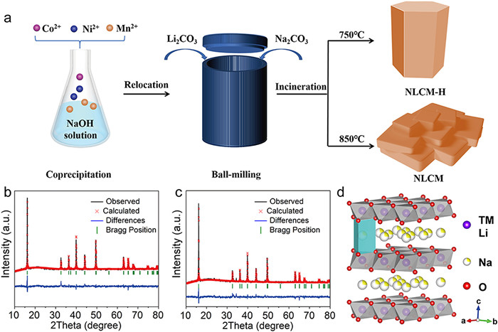
(a) Schematic illustration for the synthesis of NLCM-H and NLCM. The XRD patterns with corresponding Rietveld refinement plots of (b) NLCM-H and (c) NLCM samples, respectively. (d) Crystal structure of NLCM-H.
Increasing (010) active plane of P2-type layered cathodes with hexagonal prism towards improved sodium-storage
Dongmei Dai , Xiaobing Lai , Xiaojuan Wang , Yunting Yao , Mengmin Jia , Liang Wang , Pengyao Yan , Yaru Qiao , Zhuangzhuang Zhang , Bao Li , Dai-Huo Liu

High prices and safety concerns limit the development of lithium ion batteries (LIBs) in the field of large-scale energy storage [1-3]. Recently, sodium-ion batteries (SIBs) have attracted wide-ranging interest because of their low cost and the similar electrochemical properties of Na and Li [4-6]. However, the large ionic radius of Na+ poses a significant challenge to the stability of cathode materials. To promote the commercial application of SIBs, extensive efforts have been devoted to exploring functionally-adapted cathode materials, such as Prussian blueanalogs [7,8], layered transition metal oxides [9,10], polyanion compounds [11-13] and organic compounds [14,15]. Among them, P2-type layered oxides, especially Mn-based oxides (P2-NaxMnO2) have been recognized as one of the most potential cathode materials in view of their high theoretical capacities, natural abundance and environmental benignity [16,17].
However, Mn-based layered oxides suffer from the gliding of MO2 arising from the larger sodium ions, which eventually leads to structural degradation and fast capacity decay [18]. In addition, the irreversible anionic redox at high cell voltage (> 4.0 V) results in voltage decay and sluggish Na+ kinetics [19]. In the past few decades, many efforts have been devoted toward stabilizing anionic redox, but their cycle stability remains far less satisfied especially under fast-charge conditions [20-22]. On the contrary, there is less attention paid to improving Na+ transport kinetics, which is crucial for the electrochemical properties of cathode materials, determined by the host architecture and ion-transport tunnels. Construction of stable host structure is a prerequisite for avoiding lattice and diffusion channel collapse and ensuring reversible ion insertion/extraction. In addition, reasonable design of the diffusion-favorable orientation is more conducive to improving the ion transport kinetics of cathode materials. Thus, the key to breaking through the bottleneck of insufficient dynamics lies in building a stable host architecture with more migration tunnels.
Recently, mixed cation doping oxides have markedly improved structural stability upon cycling. Zhou et al. has revealed that layered manganese-based oxides with titanium substitution can suppress the Jahn-Teller distortion [23]. Dou et al. has synthesized a novel O3-type Na[Li0.05Mn0.5Ni0.3Cu0.1Mg0.05]O2 cathode, which could present a highly reversible sodium storage capacity and long cycling stability [24]. In addition to structural stability, the optimization of ion diffusion channels is another valid strategy to improve sodium storage performance. For example, Guo et al. designed a multiple-layer oriented stacking cathode material, which delivers remarkable rate performance due to the exposed (010) active planes [25]. Recently, Fu et al. has demonstrated that regulation of active planes could significantly improve anionic redox kinetics and rate performance of layered oxide cathodes [26]. In spite of these extraordinary exploratory works, the strategy of controllable adjustment of active crystal surfaces is still lacking, which could maximize the rapid charging and discharging ability of layered oxide cathodes.
In this work, we synthesized a P2-type layered Na0.71Ni0.16Li0.09Co0.16Mn0.6O2 with hexagonal-prism shape (denoted as NLCM-H) via a simple coprecipitation strategy followed by high-temperature calcination. Owing to the substitution of Mn3+ sites with mixed cations and crystal-facet modulation, the architecture of NLCM-H has been comprehensively strengthened, and more (010) active facets is effectively exposure, thereby improving the sodium storage kinetics and nanostructure stability of the cathode material. Specifically, the as-prepared NLCM-H exhibits superior Na-storage performance of 52.7 mAh/g at 10 C and cycling capability of 75.1 mAh/g over 200 cycles at 5 C.
Fig. 1a depicts the synthetic route to P2-type Na0.71Ni0.16Li0.09Co0.16Mn0.6O2 particles. First, the flake hydroxide precursor was synthesized using a simple coprecipitation method. The XRD pattern of the hydroxide precursor is displayed in Fig. S1a (Supporting information), which tally with the Bragg positions for Mn3O4, Co3O4, Ni(OH)2, Mn(OH)2 and Co(OH)2. After this, the precursor, lithium and sodium salts were mixed evenly by ball milling method. Subsequently, the above products were sintered at 750 ℃ for 10 h under Air to obtain hexagonal-prism Na0.71Ni0.16Li0.09Co0.16Mn0.6O2, when sintered at 850 ℃, a tabular-like Na0.71Ni0.16Li0.09Co0.16Mn0.6O2 is synthesized. The phases of NLCM-H and NLCM are examined by Rietveld refined XRD pattern (Figs. 1b and c, Tables S1 and S3 in Supporting information). All diffraction peaks can be well indexed to the space group of P63/mmc with the lattice parameters a = b = 2.8641(2), c = 11.0359(2) for NLCM-H and a = b = 2.8682(7), c = 11.0082(0) for NLCM. There are no obvious impurities in XRD pattern affirming that the doped ions have been successfully integrated into the hexagonal crystal structure (Fig. S1b in Supporting information). Based on the above structural analysis, both materials have a P2-type layered hexagonal structure (Fig. 1d). The ICP-OES analysis further confirmed the ratio of Na, Mn, Co, Ni and Li (Table S2 in Supporting information).
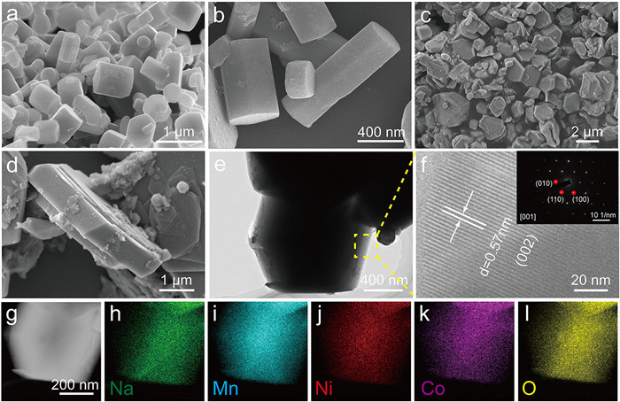
The morphology and structure of as-obtain products are studied by SEM and TEM. As shown in Fig. S2 (Supporting information), precursor presents an irregular flaky architecture with lengths of 30–100 mm and is stacked with each other. The morphology evolution of the precursor at high temperature is shown in Fig. S3 (Supporting information), the sample obtained by calcination at 650 ℃ is small particles that are not in P2-type layered structure (Figs. S3a and S4a in Supporting information). When the sintering temperature reaches 750 ℃, the morphology of the product transforms into a clear hexagonal prism shape with an average size of ca. 630 nm × 330 nm (Fig. S3b, Figs. 2a and b). When the temperature is raised again to 850 ℃, the sample exhibits a plate-like structure with larger particle sizes (0.5 µm × 3 µm) than the former (Fig. S3c, Figs. 2c and d). Micron scale plate-like products will further aggregate during the calcination process at 950 ℃ (Figs. S3d and S4b in Supporting information). The TEM image (Fig. 2e) further demonstrates hexagonal-prism architecture of NLCM-H. The clear lattice fringes with a spacing of 0.57 nm matches well with the (002) planes (Fig. 2f). Pure phase of a hexagonal crystalline structure is further corroborated by selected area electron diffraction (inset in Fig. 2f), in which hexagonal spot patterns imply the single-crystalline feature. The elemental mapping images of Na, Mn, Ni, Co and O demonstrate that the elements in NLCM-H are evenly distributed (Figs. 2g-l).
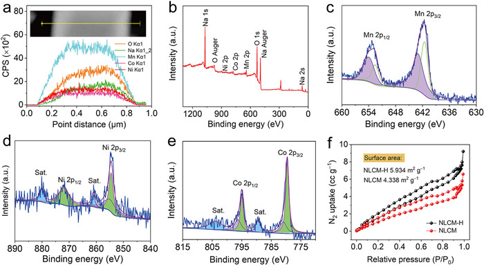
As the line-scan EDS progresses in Fig. 3a and Fig. S5 (Supporting information), the content change curves of O, Na, Mn, Co and Ni elements are basically consistent, further proving that O, Na, Mn, Co and Ni elements are uniformly distributed throughout the hexagonal prism. The composition and elemental valence state of NLCM-H are characterized by XPS. Fig. 3b shows the XPS full spectrum of NLCM-H, which corroborates the presence of Na, O, Ni, Mn, and Co in NLCM-H. As shown in Fig. 3c, the Mn 2p1/2 and Mn 2p3/2 peaks are deconvoluted into four individual subpeaks. The peaks at 643.1 eV and 654.1 eV arise from Mn4+, and the two peaks at 641.4 eV and 653.4 eV are assigned to Mn3+ [27,28]. For the Ni 2p XPS spectrum (Fig. 3d), the two main peaks at around 854.1 eV and 872.5 eV can be attributed to Ni 2p3/2 and Ni 2p1/2, accompanied by two satellite peaks, which indicaties that the valence state of Ni is +2 [29]. Besides, the subpeaks at 781.0 and 796.4 eV are indexed to Co4+ and those of 779.5 and 794.9 eV signify the presence of Co3+ in Co 2p spectrum (Fig. 3e) [30,31]. Fig. 3f shows that NLCM-H possess a much larger Brunauer–Emmett–Teller specific surface area (5.934 m2/g) than that of NLCM-H (4.338 m2/g).
The electrochemical properties of NLCM-H and NLCM were studied in the voltage window of 2.0–4.3 V. The higher voltage operation such as 2.0–4.5 V was restricted because of irreversible redox reactions (Fig. S6 in Supporting information). Electrochemical impedance spectroscopy (EIS) analysis indicates that the NLCM-H cathode has a smaller high-frequency semi-circle diameter than the NLCM cathode, implying a lower solid-state interface resistance (Fig. 4a and Table S3). Fig. 4b presents the typical CV curve at 0.1 mV/s (vs. Na/Na+). There are two redox peaks at 3.11/2.97 V and 3.78/3.54 V, which can be assigned to the low-spin Mn3+/Mn4+, Co3+/Co4+ and Ni2+/Ni4+ [32], respectively. Fig. 4c displays the first three charge–discharge curves of NLCM-H at 0.1 C (1 C = 175 mAh/g). The initial charge and discharge capacity values are 72.3 mAh/g and 120.1 mAh/g, in which the low Coulombic efficiency (CE) can be attributed to the sodium deficiency of layered oxides at the initial state. During the first charge and discharge processes, the P2 layered structure was well maintained apart from some slight shift of peak position (Fig. S7 in Supporting information). On the contrary, the reversibility of the NLCM cathode in the initial curves was not satisfactory (Fig. S8 in Supporting information). Besides, cycling stability of NLCM-H is better than that of NLCM (Fig. 4d), delivering a charge capacity of 107.5 mAh/g after 50 cycles. As shown in Figs. 4e and f, the hexagonal prism structure of NLCM-H can still be well preserved after 50 cycles, while the plate-like structure of NLCM has undergone delamination under the action of interference stress (Figs. S9a and b in Supporting information). Fig. 4g and Fig. S9c (Supporting information) show the XRD patterns of NLCM-H and NLCM before and after cycling. After 50 cycles at 0.1 C, NLCM-H still maintains the P2-type structure. However, a miscellaneous peak at 30.5° can be clearly observed in the cycled NLCM cathode. The above results fully prove that the submicron sized NLCM-H with hexagonal prism structure is stable upon Na+ deintercalation/intercalation, which can effectively reduce the structural stress to boost the cyclic stability of NLCM-H cathode. Even at a high current density of 5 C, the NLCM-H electrode still retains a large reversible capacity of 75.1 mAh/g over 200 cycles with a capacity preservation of 95.6% (Fig. S10 in Supporting information).
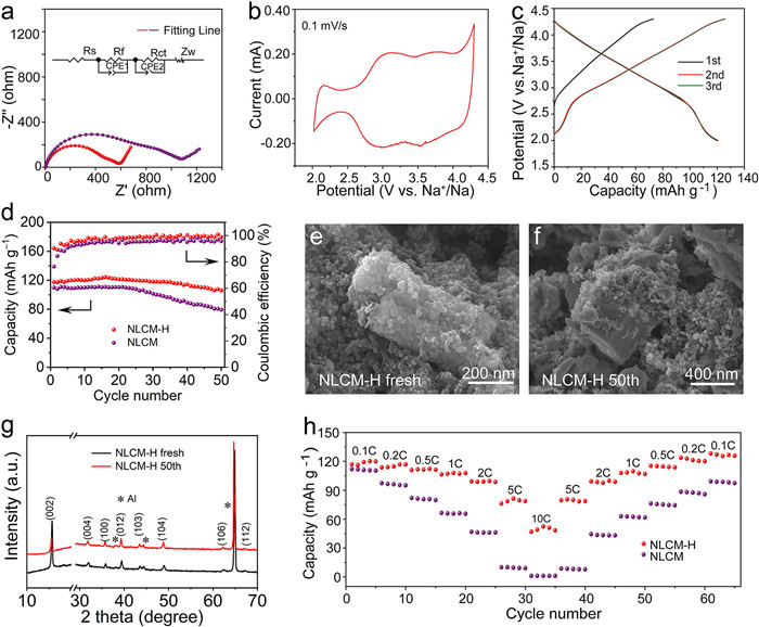
The rate performance of two electrodes are evaluated to reveal the sodium-ion diffusion potential under different current densities in Fig. 4h. The reversible capacities of NLCM-H after 5 cycles are maintained at 120.1, 116.7, 112.1, 108.4, 99.3, 80.9 and 52.7 mAh/g at 0.1, 0.2, 0.5, 1, 2, 5 and 10 C, respectively. Moreover, the capacity recovers to the original value when the current decreases from 10 C to 0.1 C again. On the contrary, NLCM exhibits lower capacity and recoverability at high current densities. The corresponding charge and discharge curves of NLCM-H electrode at various current densities are presented in Fig. S11 (Supporting information).
Galvanostatic intermittent titration technique (GITT) measurement is conducted at 0.05 C after first cycle to further understand the Na+ diffusion kinetics of NLCM-H and NLCM cathodes. In Fig. 5a, the Na+ diffusion coefficients (DNa) of NLCM-H calculated from the GITT profiles are in the range of 10–11 cm2/s, which are larger than those of NLCM during the cycling processes (Fig. S12 in Supporting information). The advantageous Na+ transport kinetics of NLCM-H cathode is further investigated by the CV profiles at different sweeping rates from 0.1 mV/s to 0.5 mV/s (Fig. 5b). The Na+ transport characteristics are depicted in Fig. S13 (Supporting information) by the Randles–Sevcik equation [33,34]. The DNa of A1, C1, A2, and C2, are determined to be 3.49 × 10⁻¹⁰, 9.49 × 10⁻¹⁰, 6.50 × 10⁻¹⁰, and 9.90 × 10⁻¹⁰ cm2/s. For NLCM electrode, the DNa of A1, C1, A2, and C2 are 3.05 × 10⁻¹⁰, 6.88 × 10⁻¹⁰, 4.88 × 10⁻¹⁰ and 5.43 × 10⁻¹⁰ cm2/s (Fig. S14 in Supporting information), respectively, agreeing well with the results calculated by the GITT. Such a high Na+ diffusion kinetics is owing to the hexagonal prism structure of NLCM-H with more (101) active plane derived from the submicron scale, which further supports the observed high-rate performance in NLCM-H. According to the following equation: i = avb, the b-value of C1, C2, A1 and A2 peaks are calculated as 0.96, 0.88, 0.89 and 0.86, suggesting that pseudocapacitive-controlled processes play important roles in Na+ storage mechanism [35-37]. As shown in Fig. 5b, the b-value of R1, R2, O1 and O2 peaks are 0.98, 0.88, 0.79 and 0.96, suggesting that a capacitive mechanism play important roles in Na+ storage (Fig. 5c). Ulteriorly, the capacitive contribution is derived via the law of i = k1v + k2v1/2 [38-40], where k1v and k2v1/2 represent the capacitive current and diffusion-controlled current, respectively. Fig. 5d unveils that the capacitive contribution (shade area) accounts for nearly 77.03% of the total capacity at 0.1 mV/s, meaning that the capacitive contribution is dominant at this sweep rate. As the sweep rate increases from 0.1 mV/s to 0.5 mV/s, the proportion of capacitive contribution also increases from 77.03% to 92.34% (Fig. 5e).
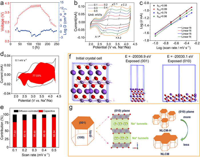
Density functional theory (DFT) calculations using VASP are performed to obtain the energy of a definite crystal face. As shown in Fig. 5f, the energy exposed to the (001) crystal surface is −2.00369 eV, which is smaller than that of (010) (−2.00301 eV). It can be seen that the formation of hexagonal prisms is driven by kinetics, and as the calcination temperature increases, the material tends to grow along (010) to form plate-like structures. Schematic illustration of microparticle was depicted to certify the relationship between morphology of products and (010) facets in Fig. 5g. Based on P2-type layered oxides with the hexagonal phase system, it can be extrapolated that the front facet of NLCM-H is (001) plane and the side facet is (010) plane. The (010) planes have open diffusion channels, which promotes Na+ transmission between the TMO2 layers. For NLCM sintered at 850 ℃, the higher temperature calcination resulted in the fusion of hexagonal prisms to form a micrometer plate-like structure, which greatly reducing the exposure of (010) crystal planes and exhibiting unsatisfactory kinetic characteristics.
In summary, an exposure (010) active planes layered P2-type Na0.71Ni0.16Li0.09Co0.16Mn0.6O2 with hexagonal prism cathode has been synthesized via an elegant coprecipitation method followed by high-temperature sintering for SIBs. The exposure of more (010) active facets by structural optimization could not only efficiently improve electrode-electrolyte contact area, thereby facilitate Na+ transport because of the short diffusion distances in the crystal structure, but also it was beneficial for a higher capacitive contribution. As a result, as-synthesized NLCM-H cathodes demonstrate a reversible capacity of 120.1 mAh/g at 0.1 C, improved rate performance of 52.7 mAh/g at 10 C, and remarkable cyclic stability with 95.6% capacity retention after 200 cycles.
The authors declare that they have no known competing financial interests or personal relationships that could have appeared to influence the work reported in this paper.
This work was financially supported by the National Natural Science Foundation of China (Nos. 52372188, 51902090), Henan Key Research Project Plan for Higher Education Institutions (No. 23A150038), 2023 Introduction of Studying Abroad Talent Program, "111" Project (No. D17007), Henan Provincial Key Scientific Research Project of Colleges and Universities (No. 23A150038), Key Scientific Research Project of Education Department of Henan Province (No. 22A150042), the National Students' Platform for Innovation and Entrepreneurship Training Program (No. 201910476010), the China Postdoctoral Science Foundation (No. 2019 M652546), and the Henan Province Postdoctoral Start-Up Foundation (No. 1901017).
Supplementary material associated with this article can be found, in the online version, at doi:
Y. Jin, P.M.L. Le, P.Y. Gao, et al., Nat. Energy 7 (2022) 718–725. doi: 10.1038/s41560-022-01055-0
G.M. Zhou, H. Chen, Y. Cui, Nat. Energy 7 (2022) 312–319. doi: 10.1038/s41560-022-01001-0
H.L. Xiong, G. Sun, Z.L. Liu, et al., Angew. Chem. Int. Ed. 60 (2021) 10334–10341. doi: 10.1002/anie.202100954
X.P. Yin, Z.X. Lu, J. Wang, et al., Adv. Mater. 34 (2022) 2109282. doi: 10.1002/adma.202109282
D. Wang, Y.P. Deng, Y.H. Liu, et al., Nano Energy 110 (2023) 108340. doi: 10.1016/j.nanoen.2023.108340
Z.Y. Gu, Y.L. Heng, J.Z. Guo, et al., Nano Res. 6 (2023) 439–448. doi: 10.1007/s12274-022-4687-6
H.W. Lee, R.Y. Wang, M. Pasta, et al., Nat. Commun. 5 (2014) 5280. doi: 10.1038/ncomms6280
J. Peng, W. Zhang, Q.N. Liu, et al., Adv. Mater. 34 (2022) 2108384. doi: 10.1002/adma.202108384
Y.M. Li, Z.Z. Yang, S.Y. Xu, et al., Adv. Sci. 2 (2015) 1500031. doi: 10.1002/advs.201500031
S.H. Guo, P. Liu, H.J. Yu, et al., Angew. Chem. Int. Ed. 54 (2015) 5894–5899. doi: 10.1002/anie.201411788
M.Z. Chen, W.B. Hua, J. Xiao, et al., Nat. Commun. 10 (2019) 1480. doi: 10.1038/s41467-019-09170-5
Z. Yang, G.L. Li, J.Y. Sun, et al., Energy Storage Mater. 25 (2020) 724–730. doi: 10.1016/j.ensm.2019.09.014
Z.Y. Gu, J.Z. Guo, Z.H. Sun, et al., Sci. Bull. 65 (2020) 702–710. doi: 10.1016/j.scib.2020.01.018
D. Li, W. Tang, C.Y. Yong, et al., ChemSusChem 13 (2020) 1991–1996. doi: 10.1002/cssc.202000131
C.G. Wang, Q. Ji, R.R. Chu, et al., ACS Appl. Energy Mater. 4 (2021) 12641–12648. doi: 10.1021/acsaem.1c02393
T. Jin, P.F. Wang, Q.C. Wang, et al., Angew. Chem. Int. Ed. 59 (2020) 14511–14516. doi: 10.1002/anie.202003972
Z.Z. Zhang, Q. Hu, J.Y. Liao, et al., Nano Lett. 23 (2023) 694–700. doi: 10.1021/acs.nanolett.2c04649
S.Y. Chu, C.C. Zhang, H. Xu, et al., Angew. Chem. Int. Ed. 60 (2021) 13366–13371. doi: 10.1002/anie.202100917
X.L. Li, T. Wang, Y.F. Yuan, et al., Adv. Mater. 33 (2021) 2008194. doi: 10.1002/adma.202008194
X. Rong, E. Hu, Y. Lu, et al., Joule 3 (2019) 503–517. doi: 10.1016/j.joule.2018.10.022
C. Cheng, C. Chen, S.Y. Chu, et al., Adv. Mater. 34 (2022) 2201152. doi: 10.1002/adma.202201152
Z.Y. Li, X.B. Ma, K. Sun, et al., ACS Appl. Mater. Interfaces 15 (2023) 17801–17813. doi: 10.1021/acsami.2c22670
T. Fang, S. Guo, K. Jiang, et al., Small Methods 3 (2019) 1800183. doi: 10.1002/smtd.201800183
J.Q. Deng, W.B. Luo, X. Lu, et al., Adv. Energy Mater. 8 (2018) 1701610. doi: 10.1002/aenm.201701610
Y. Xiao, P.F. Wang, Y.X. Yin, et al., Adv. Mater. 30 (2018) 1803765. doi: 10.1002/adma.201803765
F. Fu, X. Liu, X.G. Fu, et al., Nat. Commun. 13 (2022) 2826. doi: 10.1038/s41467-022-30113-0
S.J. Clark, M.D. Segall, C.J. Pickard, et al., Zeitschrift Fur Kristallographie 220 (2005) 567–570. doi: 10.1524/zkri.220.5.567.65075
Y.F. Zhu, Y. Xiao, W.B. Hua, et al., Angew. Chem. Int. Ed. 59 (2020) 9299–9304. doi: 10.1002/anie.201915650
P.F. Wang, Y. You, Y.X. Yin, et al., J. Mater. Chem. A 4 (2016) 17660–17664. doi: 10.1039/C6TA07589D
J.U. Choi, J. Kim, J.Y. Hwang, et al., Nano Energy 61 (2019) 284–294. doi: 10.1016/j.nanoen.2019.04.062
J. Sun, N. Guo, T. Song, et al., Adv. Powder Mater. 1 (2022) 100023. doi: 10.1016/j.apmate.2021.11.009
L.P. Duan, Y.F. Xu, Z.Z. Zhang, et al., J. Mater. Chem. A 9 (2021) 22820–22826. doi: 10.1039/d1ta07108d
H.J. Liang, Z.Y. Gu, X.X. Zhao, et al., Sci. Bull. 67 (2022) 1581–1588. doi: 10.1016/j.scib.2022.07.002
Z.Z. Zhang, J.L. Sun, L.P. Duan, et al., J. Mater. Chem. A 10 (2022) 554–560. doi: 10.1039/d1ta09739c
D.L. Ba, W.H. Zhu, Y.Y. Li, J.P. Liu, Rare Met. 41 (2022) 4075–4085. doi: 10.1007/s12598-022-02082-2
X. Xu, S. Wang, S. Guo, et al., Adv. Powder Mater. 1 (2022) 100027. doi: 10.1016/j.apmate.2021.12.003
Z.Z. Zhang, Y.R. Qiao, Q.H. Deng, et al., Inorg. Chem. Front. 10 (2023) 1286–1293. doi: 10.1039/d2qi02393h
L.F. Shen, Y. Wang, H.F. Lv, et al., Adv. Mater. 30 (2018) 1804378. doi: 10.1002/adma.201804378
S. Xiao, J. Jiang, Y. Zhu, et al., Adv. Powder Mater. 2 (2023) 100120. doi: 10.1016/j.apmate.2023.100120
K.Y. Zhang, Z.Y. Gu, E.H. Ang, et al., Mater. Today 54 (2022) 189–201. doi: 10.1016/j.mattod.2022.02.013

Figure 1 (a) Schematic illustration for the synthesis of NLCM-H and NLCM. The XRD patterns with corresponding Rietveld refinement plots of (b) NLCM-H and (c) NLCM samples, respectively. (d) Crystal structure of NLCM-H.

Figure 2 SEM images of (a, b) NLCM-H and (c, d) NLCM. (e) TEM image, (f) HRTEM image, (g) scanning transmission electron microscopy image and (h–l) the corresponding elemental mapping of NLCM-H. Inset in (f): SAED pattern of NLCM-H.

Figure 3 (a) Line-scan EDS elemental distribution curves of O, Na, Mn, Co, and Ni on the NLCM-H. (b) XPS survey scan, (c) high-resolution Mn 2p XPS spectrum, (d) high-resolution Ni 2p XPS spectrum, and (e) high-resolution Co 2p XPS spectrum of NLCM-H. (f) N2 adsorption–desorption isotherm of NLCM-H and NLCM.

Figure 4 (a) Nyquist plots of the NLCM-H and NLCM electrodes. (b) CV curve and (c) galvanostatic charge–discharge curves of the initial three cycles of NLCM-H at 0.1 C. (d) Cycling performance at 0.1 C of NLCM-H and NLCM. SEM images of (e) the fresh electrode and (f) the electrode after 50 cycles for NLCM-H. (g) XRD patterns of the fresh electrode and the electrode after 50 cycles for NLCM-H. (h) Rate capabilities of NLCM-H and NLCMs.

Figure 5 GITT curves and the concerned Na+ diffusion coefficients of (a) NLCM-H. (b) CV curves at diverse scanning rates and (c) plot of log(current) vs. log(scan rate) from CV, (d) pseudocapacitive contribution at 0.1 mV/s shown by the shaded region, and (e) percentage of pseudocapacitive contributions of NLCM-H. (f) DFT computations: Initial crystal structure of P2-Na0.71Li0.09Mn0.6Co0.16Ni0.16O2 and the energy of a definite crystal face of (001) and (010). (g) Schematic illustration of microparticles with (010) facets for NLCM-H and NLCM.

 扫一扫看文章

扫一扫关注我们
 DownLoad:
 下载:
下载:
 下载:
下载: