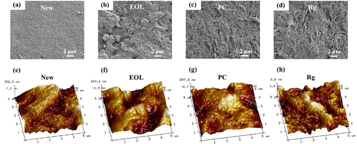
Figure 1.
SEM images of the (a) new, (b) EOL, (c) PC, and (d) Rg membrane. AFM 3D images of the (e) new, (f) EOL, (g) PC, and (h) Rg membrane.

Growing global water crisis necessitates the implementation of sustainable water resource recycling and utilization [1–4]. The membrane bioreactor (MBR) is an efficient wastewater treatment technology that combines a membrane filtration with a biological process [5], gaining increasing popularity owing to the advantages of high separation efficiency and favorable effluent quality [6–8]. In particular, incorporation of microfiltration (MF) or ultrafiltration (UF) within MBR systems has been widely used as an effective and convenient technology for municipal wastewater treatment and reuse [9–12].
However, in the widespread application of MBRs, membrane inevitably reaches its end-of-life (EOL) in the treatment process after the long-term operation. Even with frequent chemical cleaning, the membrane eventually fails to satisfy the water production due to the accumulation of irrecoverable foulants or possible structural damage [13–16]. Consequently, the replacement and disposal of the EOL membrane lead to considerable labor waste and economic burden, hindering the widespread application of membrane technology [17–20].
The recycling of EOL membranes is recognized as a promising and cost-effective approach for sustainable membrane-based wastewater treatment technology [21,22]. Downcycling of EOL reverse osmosis (RO) or nanofiltration (NF) membranes for obtaining NF or UF membranes refers to conversion process using different chemical agents [23–25]. Upcycling of EOL low-pressure membranes can be achieved by interfacial polymerization on the membrane surface for fabricating high-pressure membranes with significant salt rejection rate [26]. Nevertheless, downcycling or upcycling of EOL membranes encounters challenges that need to be addressed. These include identifying appropriate application scenarios for regenerated (Rg) membranes and considering carbon emissions resulting from long-distance transportation. Considering the practical aspect, regeneration of EOL membranes is more valuable for membrane users, as it enables the direct application of Rg membranes within the original water treatment facility, showcasing great potential for future enterprise market applications.
Herein, an eco-friendly strategy based on triethyl phosphate (TEP) solvent for regenerating EOL polyvinylidene fluoride (PVDF) membranes was selected. TEP possesses low toxicity compared to other traditional solvents [27,28], and has a good affinity with PVDF material as TEP has been used as the solvent to manufacture PVDF membranes [29–31]. Therefore, we hypothesize that incorporating TEP solvent-based processing in EOL membrane regeneration could potentially enable effective removal of recalcitrant irrecoverable foulants and restoration of membrane water permeance.
We firstly evaluated the effectiveness and mechanisms of the membrane regeneration strategy. Surface morphologies, filtration performance, surface functional groups and chemical composition of the membranes were identified. Real wastewater treatment performance and critical flux determination of the membranes were measured in a lab-MBR (membrane bioreactor). We further elaborated the mechanisms of how TEP solvent-based processing contributed to the achievement of performance recovery and EOL membrane regeneration. This study highlights in addressing the challenges associated with irrecoverable fouling removal and the sustainable recycling of membrane materials for wastewater treatment technology.
The EOL membrane preliminarily applied with chemical agents for removing irreversible foulants, was denoted as the preliminarily cleaned (PC) membrane. The PC membrane was then subjected to TEP solvent-based processing to remove irrecoverable fouling, which could be referred to as the Rg membrane. The detailed experiment procedure was available in Supporting information. The scanning electron microscopy (SEM) and atomic force microscopy (AFM) analyses were employed to investigate the morphological changes of the EOL membrane after the process of preliminary cleaning and solvent-based processing (Fig. 1). Firstly, the new membrane was observed with a clean and smooth surface (Figs. 1a and e). In contrast, the EOL membrane displayed the accumulation of foulants on the surface (Fig. 1b), which could not be removed by physical cleaning, resulting in increased surface roughness compared to the new membrane (an increase of the average roughness (Ra) from 80.5 ± 13.1 nm to 165 ± 18.5 nm) [32]. After preliminary cleaning, foulants on the EOL membrane surface were partially removed (Fig. 1c). However, the roughness of the PC membrane increased unexpectedly (Ra = 185 ± 24.6 nm), which could be attributed to the oxidation of membrane with sodium hypochlorite solution (NaClO) in preliminary cleaning step, leading to the slight fracture and transformation of PVDF polymers [33,34].
After cleaning by TEP solvent, the PVDF membrane possessed a much clearer surface (Figs. 1d and h). In addition, the corresponding roughness of the Rg membrane (Ra = 79.1 ± 11.0 nm) was nearly the same with that of the new one, which possibly due to the removal of irrecoverable foulants from membranes [35]. Therefore, we hypothesized that TEP solvent, which exhibited good affinity with PVDF, potentially modifying the structure of PVDF membrane during the solvent-based processing.
To further analyze the efficiency of the eco-friendly strategy for regenerating EOL membranes, membrane filtration performance was systematically evaluated (Fig. 2a). The new membrane experienced a substantial decline in water permeance from 411.6 ± 14.0 L m−2 h−1 bar−1 to 38.2 ± 22.4 L m−2 h−1 bar−1 upon reaching its EOL after long-term operation. After preliminary cleaning, the water permeance slightly increased to 110.2 ± 44.6 L m−2 h−1 bar−1. As expected, the Rg membrane exhibited a considerable water permeance (534.8 ± 45.7 L m−2 h−1 bar−1), surpassing that of the new membrane. Meanwhile, all of the membranes had comparable rejection rates, exhibiting over 92% (Fig. 2a). The findings revealed that the eco-friendly strategy with TEP for regenerating EOL membranes could achieve membrane filtration performance comparable to that of new membranes.

The hydrophilicity of membranes was determined by water contact angle measurements (Fig. 2b). In general, an increased contact angle corresponds to a higher hydrophobicity. The new membrane exhibited a water contact angle of 92.3° ± 1.1°. The contact angle of the EOL membrane increased to 100.3° ± 1.3° result from the accumulation of hydrophobic foulants [36]. Furthermore, the membrane after preliminary cleaning with NaClO and critic acid exhibited a slightly higher contact angle (106.2° ± 2.6°), indicating a potential increase in hydrophobicity of the membrane due to the effect of preliminary cleaning process [37]. As a result of the impact of solvent-based processing for removing hydrophobic foulants from the membrane, water contact angle of the Rg membrane exhibited a remarkable decrease to 95.5° ± 4.3°, showing a more hydrophilic surface compared with the EOL or PC membrane.
The attenuated total reflectance Fourier transform infrared spectroscopy (ATR-FTIR) and X-ray photoelectron spectroscopy (XPS) analyses were conducted to investigate the surface chemical groups and elemental composition of membranes (Figs. 2c and d). For all samples, the peaks at 3205 cm−1 and 1190 cm−1 were assigned to C-F stretching and bending vibration, respectively, which were characteristic signatures for identifying PVDF materials (Fig. 2c) [38]. As for the new membrane, the peak located at 1667 cm−1 may correspond to C=O stretching bonds in polyvinylpyrrolidone (PVP), a commonly incorporated additive during the membrane manufacturing process to enhance hydrophilicity [39]. The peak intensity at 1667 cm−1 in the EOL membrane exhibited a decrease, which could be attributed to the possible degradation of PVP in the long-time operation. Besides, for the EOL membrane, a reduction in the intensity of C-F stretching peak at 1190 cm−1 was also observed. This finding was consistent with the XPS spectra (Fig. 2d), in which the EOL membrane presented the lowest F 1s signal compared with other membranes. Thanks to the preliminary cleaning and solvent-based processing, the Rg membrane presented increased F 1s and decreased O 1s signals in XPS spectra, which demonstrated the elimination of foulants from the membrane. In addition, the presence of the elements O, N in the new membrane suggested the incorporation of hydrophilic additives [40], which was verified by the FTIR spectra result (Fig. 2c). The mechanical and thermal stability of the membranes was further characterized (Figs. S4 and S5 in Supporting information), revealing that the solvent-based processing with TEP did not adversely affect the stability of the membrane in the regeneration process. Furthermore, the X-ray diffraction characterization results demonstrated that the eco-friendly membrane regeneration strategy had no impact on the crystallization state of the PVDF membrane (Fig. S6 in Supporting information).
To assess the antifouling performance of the membranes, flux-step experiments were conducted with critical flux (Jc) determination in a MBR system fed with sewage sludge. The critical flux refers to the threshold at which the fouling rate becomes significantly notable [41]. Consequently, Jc serves as a key indicator for membrane users to determine the appropriate time for membrane cleaning, and the Jc of different membranes could reflect their resistance to fouling [42]. Flux-TMP profile with operation time of four different membranes was performed from a low flux value (Fig. 3a). For each membrane, TMP initially remained stable at the imposed flux, but started to increase rapidly at a certain time point. The new membrane exhibited the longest operation time (about 150 min) until pressure reached 40 kPa. In contrast, the EOL membrane exhibited the fastest increasing rate of TMP, which increased rapidly from 17.9 kPa to 42.2 kPa in 45 min. The PC membrane had a slower increasing rate of TMP than the EOL membrane, but still presented a relatively high fouling tendency. The TMP of the Rg membrane increased slowly during the first 45 min (from 6.4 kPa to 9.7 kPa) and then increased rapidly up to 45 kPa at around 140 min. It could be inferred that the Rg membrane exhibited a comparable antifouling performance to the new membrane.

Furthermore, the rate of TMP increase (dP/dt) against flux was recorded, aiming to accurately evaluate and identify membrane fouling behavior during critical flux evaluation. Significant variations in fouling rate, dP/dt, were evident among the different membranes (Fig. 3b). For higher fluxes, a conspicuous exponential correlation between dP/dt and the flux was observed. Notably, the Rg membrane exhibited significantly lower fouling rates, evidenced by the dP/dt values at equivalent fluxes, in comparison to both the PC and EOL membranes. Based on the data analysis, the Jc for the Rg membrane was determined to be 15.2 L m−2 h−1 (corresponding to dP/dt ≥ 0.1 kPa/min). In the same way, the Jc of the EOL, PC and new membranes were determined as 4.0, 10.5 and 20.1 L m−2 h−1, respectively.
Flux versus the average TMP at each flux step (Pave) remained approximately linear, indicating a constant permeability (K) for the membranes until flux value up to the Jc. Beyond Jc, the permeability of membranes rapidly declined, eventually reaching a specific value at the highest tested flux (Fig. 3c). For the new membrane, the linear region extended to the flux of 20.1 L m−2 h−1, beyond which K decreased to 79.7 L m−2 h−1 bar−1. In comparison with the new membrane, the permeability of the PC membrane and especially the EOL membrane for treating sewage sludge decreased noticeably with the increasing of pressure. However, the Rg membrane demonstrated a permeability recovery that approached the level of the new membrane, with a final permeability K reaching 67.4 L m−2 h−1 bar−1. Obviously, the Rg membrane presented substantially less fouling propensity than the PC membrane in MBR.
In order to further assess the long-term performance of Rg membranes, filtration tests for treating municipal wastewater in a lab-scale MBR were carried out. The water quality of the effluent for each membrane was evaluated (Fig. 4). No distinct difference was noticed in chemical oxygen demand (COD), ammonia nitrogen (NH4+-N) and turbidity in the permeate of the new, EOL, PC, and Rg membranes. The effluent COD of the Rg membrane was 46.3 ± 1.5 mg/L, achieving a removal rate over 90% (Fig. 4a). Besides, the effluent of the Rg membrane demonstrated NH4+-N and turbidity levels of 3.1 ± 0.3 mg/L and 0.2 ± 0.1 NTU, respectively, which were close to the effluent of the new membrane (Figs. 4b and c). The effluent of the Rg membrane met the discharge standard of pollutants for urban wastewater treatment plants in China [43], highlighting the efficacy of membrane regeneration strategy in guaranteeing the effluent quality in MBR-based municipal wastewater treatment.

For elucidating the mechanism of EOL membrane regeneration, the method of three-dimensional excitation (Ex)-emission (Em) matrix spectroscopy (3D-EEM) was employed to characterize different membranes (Fig. 5a). When compared to the new membrane, a new peak labeled as Peak A, emerged in the spectra of the EOL membrane at an Ex/Em wavelength of 420-430/360-375 nm, which is associated with humic acid (HA)-like substances [44]. As membrane regeneration process advanced, the fluorescence intensity of peak A gradually decreased, illustrating a reduction of foulants on membrane surface. These findings demonstrated that humic substances may significantly contribute to both recoverable and irrecoverable fouling [35,45].

To further gain insights into the composition of irrecoverable foulants, the TEP solvent used for regenerating the EOL membrane was gathered and subjected to spectroscopic analysis (Fig. 5b). The FTIR spectra shows that the peak at 1640 cm−1 emerged in the used solvent in comparison with the pristine solvent, which could be attributed to the aromatic C=C vibrations in HA foulants [46]. Furthermore, the porosity of PVDF membranes were determined for explaining the changes of membrane performance during membrane regeneration process (Fig. 5c). A significant decrease in average porosity of the EOL membrane compared to the new one was observed, mainly due to severe blockage of membrane pores by foulants during long-term operation. After the treatment of preliminary cleaning, the porosity of the PC membrane slightly increased. Furthermore, the Rg membrane exhibited a notable increase in membrane porosity, illustrating that solvent-based processing restored the membrane almost to initial state. In addition, the higher porosity of the membrane was likely consistent with increased water permeance, as a consequence of improved membrane performance due to the efficacy of membrane regeneration strategy.
The possible mechanism underlying the eco-friendly strategy for regenerating the EOL membrane can be proposed as follows (Fig. 6): (ⅰ) the preliminary cleaning step removed part of foulants, excluding the irrecoverable foulants; (ⅱ) HA substances trapped in PVDF membrane pores were more readily dislodged by the following solvent-based processing via the strong TEP-PVDF interaction, which restored the membrane porosity almost to the level of new membrane. Meanwhile, the Rg membrane demonstrated an improved antifouling performance in real municipal wastewater treatment process.

In this study, the EOL PVDF hollow fiber membrane was successfully regenerated via the eco-friendly strategy with TEP solvent. Consequently, the Rg membrane demonstrated a cleaner surface and higher water permeance compared to the EOL membrane. Compared with the PC membrane, better hydrophilicity of the Rg membrane was attributed to the efficient elimination of hydrophobic foulants from membrane surface. Meanwhile, the Rg membrane exhibited better resistance to fouling by determining the critical flux, which was regarded as a good indicator for predicting the long-term fouling behavior. More importantly, the membrane regeneration strategy was capable of guaranteeing the effluent quality in MBR for treating real municipal wastewater. This work may be helpful to understand the mechanism of solvent-based processing for removing irrecoverable membrane foulants, and provide guideline for designing economical and effective strategies to regenerate the membrane which was initially considered to have reached its end of lifespan.
The authors declare that they have no known competing financial interests or personal relationships that could have appeared to influence the work reported in this paper.
We would like to thank National Natural Science Foundation of China (Nos. 51925806 and 52200108) for the financial support of the work. This study is also supported by the Chenguang Program of Shanghai Education Development Foundation and Shanghai Municipal Education Commission.
Supplementary material associated with this article can be found, in the online version, at doi:
S.M. Riley, J.M.S. Oliveira, J. Regnery, T.Y. Cath, Sep. Purif. Technol. 171 (2016) 297–311. doi: 10.1016/j.seppur.2016.07.008
D. Metcalfe, P. Jarvis, C. Rockey, S. Judd, Sep. Purif. Technol. 163 (2016) 173–180. doi: 10.1016/j.seppur.2016.02.046
A. Zouboulis, D. Zamboulis, K. Szymanska, Sep. Purif. Technol. 137 (2014) 43–52. doi: 10.1016/j.seppur.2014.09.023
Q. Gao, L. Duan, J. Liu, H. Zhang, Y. Zhao, J. Clean. Prod. 417 (2023) 138029. doi: 10.1016/j.jclepro.2023.138029
B. Zhang, D. Huang, Y. Shen, et al., J. Clean. Prod. 273 (2020) 123124. doi: 10.1016/j.jclepro.2020.123124
G. Kang, Y. Cao, J. Membr. Sci. 463 (2014) 145–165. doi: 10.1016/j.memsci.2014.03.055
F. Liu, N.A. Hashim, Y. Liu, M.R.M. Abed, K. Li, J. Membr. Sci. 375 (2011) 1–27. doi: 10.1016/j.memsci.2011.03.014
Z. Xiong, J. Liu, Y. Yang, et al., J. Membr. Sci. 644 (2022) 120076. doi: 10.1016/j.memsci.2021.120076
Y. Chang, Y.J. Shih, R.C. Ruaan, et al., J. Membr. Sci. 309 (2008) 165–174. doi: 10.1016/j.memsci.2007.10.024
A.K. Fritzsche, A.R. Arevalo, M.D. Moore, et al., J. Membr. Sci. 68 (1992) 65–78. doi: 10.1016/0376-7388(92)80150-I
Y. Chen, Q. Deng, J. Xiao, et al., Polymer 48 (2007) 7604–7613. doi: 10.1016/j.polymer.2007.10.043
X. Wang, C. Wang, C.Y. Tang, T. Hu, X. Li, Y. Ren, J. Membr. Sci. 527 (2017) 1–7. doi: 10.1016/j.memsci.2016.12.062
S.S. Madaeni, Water Res. 33 (1999) 301–308. doi: 10.1016/S0043-1354(98)00212-7
Y.R. Chang, Y.J. Lee, D.J. Lee, J. Taiwan Inst. Chem. Eng. 94 (2019) 88–96. doi: 10.1016/j.jtice.2017.12.019
M. Pontié, S. Awad, M. Tazerout, O. Chaouachi, B. Chaouachi, Desalination 423 (2017) 30–40. doi: 10.1016/j.desal.2017.09.012
Y. Yang, Q. Lai, S. Mahmud, et al., J. Membr. Sci. 645 (2022) 120204. doi: 10.1016/j.memsci.2021.120204
W. Lawler, Z. Bradford-Hartke, M.J. Cran, et al., Desalination 299 (2012) 103–112. doi: 10.1016/j.desal.2012.05.030
E. Ould Mohamedou, D.B. Penate Suarez, F. Vince, P. Jaouen, M. Pontie, Desalination 253 (2010) 62–70. doi: 10.1016/j.desal.2009.11.032
P.H. Nielsen, M. Hauschild, Int. J. LCA 3 (1998) 158–168. doi: 10.1007/BF02978824
S.M. Al-Salem, P. Lettieri, J. Baeyens, Waste Manage 29 (2009) 2625–2643. doi: 10.1016/j.wasman.2009.06.004
W. Lawler, J. Alvarez-Gaitan, G. Leslie, P. Le-Clech, Desalination 357 (2015) 45–54. doi: 10.1016/j.desal.2014.10.013
J. Ahmed, Y. Jamal, Environ. Sci. Pollut. Res. Int. 28 (2021) 34042–34050. doi: 10.1007/s11356-020-11117-z
J.M. Veza, J.J. Rodriguez-Gonzalez, Desalination 157 (2003) 65–72. doi: 10.1016/S0011-9164(03)00384-9
J.J. Rodríguez, V. Jiménez, O. Trujillo, JoséM. Veza, Desalination 150 (2002) 219–225. doi: 10.1016/S0011-9164(02)00977-3
V.T. Do, C.Y. Tang, M. Reinhard, J.O. Leckie, Environ. Sci. Technol. 46 (2012) 852–859. doi: 10.1021/es203090y
R. Dai, H. Han, T. Wang, et al., ACS Sustain. Chem. Eng. 9 (2021) 10352–10360. doi: 10.1021/acssuschemeng.1c03481
J. Chang, J. Zuo, L. Zhang, G.S. O'Brien, T.S. Chung, J. Membr. Sci. 539 (2017) 295–304. doi: 10.1016/j.memsci.2017.06.002
W. Xie, T. Li, A. Tiraferri, et al., ACS Sustain. Chem. Eng. 9 (2021) 50–75. doi: 10.1021/acssuschemeng.0c07119
Q. Wang, Z. Wang, Z. Wu, Desalination 297 (2012) 79–86. doi: 10.1016/j.desal.2012.04.020
O. Benhabiles, F. Galiano, T. Marino, et al., Molecules 24 (2019) 724. doi: 10.3390/molecules24040724
T. Marino, S. Blefari, E.D. Nicolò, A. Figoli, Green Process. Synth. 6 (2017) 295–300. doi: 10.1515/gps-2016-0165
J.H. Kweon, J.H. Jung, S.R. Lee, et al., Desalination 286 (2012) 324–331. doi: 10.1016/j.desal.2011.11.043
A. Simon, W.E. Price, L.D. Nghiem, J. Taiwan Inst. Chem. Eng. 44 (2013) 713–723. doi: 10.1016/j.jtice.2013.01.030
Q. Wang, H. Zeng, Z. Wu, J. Cao, Appl. Surf. Sci. 428 (2018) 289–295. doi: 10.1016/j.apsusc.2017.09.056
C. Tian, T. Wang, H. Han, R. Dai, Z. Wang, Environ. Sci. Technol. 56 (2022) 12563–12572. doi: 10.1021/acs.est.2c02321
P.J. Evans, M.R. Bird, Food Bioprod. Process 84 (2006) 292–301. doi: 10.1205/fbp06030
W. Cai, Y. Liu, J. Membr. Sci. 511 (2016) 84–91. doi: 10.1016/j.memsci.2016.03.039
L. Marbelia, M.R. Bilad, I.F.J. Vankelecom, Sep. Purif. Technol. 213 (2019) 276–282. doi: 10.1016/j.seppur.2018.12.045
Z. Zhou, G. Huang, Y. Xiong, et al., Environ. Sci. Technol. 51 (2017) 14342–14351. doi: 10.1021/acs.est.7b03952
J.R. Du, S. Peldszus, P.M. Huck, X. Feng, Water Res. 43 (2009) 4559–4568. doi: 10.1016/j.watres.2009.08.008
P. Le Clech, B. Jefferson, I.S. Chang, S.J. Judd, J. Membr. Sci. 227 (2003) 81–93. doi: 10.1016/j.memsci.2003.07.021
S. Ognier, C. Wisniewski, A. Grasmick, J. Membr. Sci. 229 (2004) 171–177. doi: 10.1016/j.memsci.2003.10.026
X.H. Wang, X. Wang, G. Huppes, R. Heijungs, N.Q. Ren, J. Clean. Prod. 94 (2015) 278–283. doi: 10.1016/j.jclepro.2015.02.007
W. Chen, P. Westerhoff, J.A. Leenheer, K. Booksh, Environ. Sci. Technol. 37 (2003) 5701–5710. doi: 10.1021/es034354c
K. Katsoufidou, S.G. Yiantsios, A.J. Karabelas, Desalination 220 (2008) 214–227. doi: 10.1016/j.desal.2007.02.038
S.C. Low, Q.H. Ng, L.S. Tan, J. Polym. Res. 26 (2019) 70. doi: 10.1007/s10965-019-1734-4

Figure 1 SEM images of the (a) new, (b) EOL, (c) PC, and (d) Rg membrane. AFM 3D images of the (e) new, (f) EOL, (g) PC, and (h) Rg membrane.

Figure 2 Performance and characterization of various PVDF membranes: (a) water permeance and rejection rate of SA, (b) water contact angle, (c) ATR-FTIR spectra and (d) XPS spectra.

Figure 3 (A) Variation of TMP with time by the flux-step method, (b) fouling rate as a function of flux and (c) comparison between permeability for various membranes. (*) symbolizes the dashed line positioned at 0.1 kPa/min, marking the threshold where the rate of TMP increase becomes significant.

Figure 4 Performance of various membranes for treating municipal wastewater: (a) COD, (b) NH4+-N and (c) turbidity in the effluent of membranes.

Figure 5 Difference analysis of (a) fluorescence spectra of the new, EOL, CC and Rg membrane, (b) ATR-FTIR spectra of pristine and used TEP solvent, and (c) the porosity of the new, EOL, CC and Rg membrane.

 扫一扫看文章

扫一扫关注我们
 DownLoad:
 下载:
下载:

 下载:
下载: