Citation:
Jie Ren, Hao Zong, Yaqun Han, Tianyi Liu, Shufen Zhang, Qiang Xu, Suli Wu. Visual identification of silver ornament by the structural color based on Mie scattering of ZnO spheres[J]. Chinese Chemical Letters,
2024, 35(9): 109350.
doi:
10.1016/j.cclet.2023.109350
Visual identification of silver ornament by the structural color based on Mie scattering of ZnO spheres
English
Visual identification of silver ornament by the structural color based on Mie scattering of ZnO spheres
State Key Laboratory of Fine Chemicals, Frontier Science Center for Smart Materials, School of Chemical Engineering, Dalian University of Technology, Dalian 116024, China
b.
Instrumental Analysis Center of Dalian University of Technology, Dalian 116024, China
Received Date:
29 October 2023 Accepted Date:
27 November 2023 Revised Date:
20 November 2023 Available Online:
15 September 2024
Abstract:
Structural colors originated from Mie scattering of dielectric spheres can be regulated by the coupling effect between them and substrates. Here a rapid visual identification method of silver ornaments was proposed by the coupling effect of ZnO spheres with them. Both simulation and experimental results proved that, by coupling with different metal substrates, the Mie resonance scattering peaks of ZnO spheres with dimeter of 700 nm showed different degrees of redshift, which lead to different structural color appeared when ZnO spheres deposited on different metal surfaces with a similar appearance. A red structural color was displayed on the surface of the real silver ornament and a yellow-green structural color was shown on the surface of the cupronickel ornament. This method is quite simple and low-cost because it only needs to spray the dispersion of ZnO spheres on the ornament surface. Due to the mild chemical properties of the ZnO, covering and erasing ZnO spheres on the surface of silver would not corrode the silver ornament. Finally, an atomizer method was used for portable and daily testing. This work opens new perspectives on the visual identification of silver.
From the pioneering works of Schiff [1] in developing "spot tests" for fast analyte discrimination, visual identification has always attracted the multitudinous analytical chemical researcher's interest due to its simple and inexpensive instrument, fast speed, and low sample and reagents consumption. Nowadays visual identification products are widely used in our scientific research work and daily life, including acid-base indicator [2], dye tracing method [3], laser-induced fluorescence [4] and smartphone applications [5], etc. Color changes of traditional visual identification methods are usually provided by chemical reactions. Hence, these types of discoloration are generally irreversible and take time to reach a steady state, which is inconvenient for the user.
Recently, structural colors based on optical systems of dielectric nanoscale structures have shown great potential in detection, chemical sensing, anti-counterfeiting, and molecular identification [6–10]. Structural color is usually generated from the interaction of the incident light and the nano- or micro-structure in an artificial material [11–13]. When the state of the structures was changed, a corresponding structural color change occurred, and the color changes were usually reversible [14,15]. Based on these properties, such structures are typically reusable, eco-friendly, rapidly responsive, and do not rely on high-tech equipment [16–18]. For example, Kou et al. demonstrated a structurally colored photonic crystal (PC) sensor for Hg2+ based on a novel photonic material with tailored multiple recognition sites [19]. Wu et al. designed a kind of artificial chameleon skin with a two-step filling strategy to fabricate non-close-packed PC films with highly sensitive thermal and mechanochromic responses [20]. Luo et al. proposed a category of PC to detect pH, solvent, and temperature [21]. Although these PC-based detectors have good performance, the construction of the structure is always complex, which limits their use in daily life. Mie resonance is another way to generate structural colors [22–24]. Different from PC, structural colors based on Mie resonance are generally caused by single dielectric particles instead of complex nano- or micro-structure, which makes it possible to construct visual identification with simple structure [25,26]. In recent years, dielectric spheres with moderate-refractive-index (n = 1.7–3.0, such as TiO2, Cu2O, CdS, ZnS and ZnO), which can easily be prepared by wet chemical method, have become new candidates to generate Mie resonance structural colors [27–31]. According to the mechanism of Mie resonance, their structural colors are not only related to the size of the dielectric particle [32,33], but also rely on the substrate, which provides a possibility to distinguish different substrates by depositing dielectric spheres with suitable size on them [34–36].
Here, we propose a visual identification method to distinguish real silver ornament from other metals with similar appearance by the coupling effect between Mie scattering of ZnO dielectric spheres and metal substrates. Through finite difference time-domain (FDTD) simulations and experiments, it is proved that the 700 nm ZnO spheres showed different Mie structural colors on different metal substrates. A red structural color is shown on the surface of the real silver ornament and a yellow-green structural color is shown on the surface of the cupronickel (fake silver) ornament. Though simply spraying ZnO spheres dispersion on the ornament by an atomizer, the structural color can be immediately and easily observed by the naked eyes in natural light not relying on expensive equipment and additional light source. The preparation of ZnO spheres by wet chemical method is simple and the identification requires only a small number of spheres, which means the low cost of this method. Due to the mild chemical properties of the ZnO, covering and erasing ZnO spheres on the surface of silver will not corrode the silver ornament. This work provides a convenient method for the identification of silver and facilitates its applications in the field of visual identification.
Zinc acetate dihydrate (99%) was purchased from Shanghai Macklin Biochemical Co., Ltd. Poly(vinylpyrrolidone) (PVP, M = 40,000) was purchased from Sigma-Aldrich Co., Ltd. Diethylene glycol (DEG, 99%) and ethanol (EtOH, 99.9%) were both purchased from Sinopharm Chemical Reagent Co., Ltd. All chemicals were used directly as received without further purification. The atomizer, spray gun and fake silver ornament were purchased at the local market.
Monodisperse ZnO spheres were prepared according to our previous work [28]. Briefly, ZnO spheres with an average size of 300 and 700 nm can be prepared when zinc acetate dehydration of 0.83 and 2.11 g was used, respectively. The white products are separated from the solution by centrifugation and washed with excessive ethanol and water at least three times.
Preparation by spray gun method: The ultrasonic dispersed spheres were dispersed in absolute ethanol with a mass fraction of 1 wt%. The suspension should be put in ultrasonic cleaning machine at least 0.5 h to disperse the ZnO spheres. Then the suspension was sprayed onto a metal panel by a spray gun. The spray gun was placed about 30 cm away from the panel, and the pressure applied to the spray gun was about 2 MPa. The spraying speed was about 0.5 cm/s.
Preparation by atomizer method: The ultrasonic dispersed ZnO ethanol solution with a mass fraction of 0.5 wt% was canned into the atomizer. Then, SDS (0.05 wt%) was added into suspension. The suspension should be put in ultrasonic cleaning machine at least 0.5 h to disperse the ZnO spheres. Finally, the suspension was spray on the heated metal surface (80 ℃) with the atomizer 2, 3 times.
The simulated reflectance spectra were calculated with commercial finite-difference time-domain (FDTD) software (Lumerical) in simulations. The refractive index of ZnO was set as 1.7. In the case of couples of spheres, the perfectly matched layers (PMLs) were imposed in all of the directions as the boundary condition. In both cases, a plane wave was placed above the structure for a reflection spectral calculation.
XRD pattern of the obtained ZnO spheres was recorded by a Rigaku SmartLab 9KW diffractometer with Cu-Kα radiation. The size phase and morphology of the spheres were characterized by field emission scanning electron microscope (FE-SEM, Nova Nanosem 450), transmission electron microscopy (TEM), selected-area electron diffraction (SAED), and high-resolution TEM (HR-TEM, FEI TF30). The normal-incidence optical reflection spectra and the changes in light reflection intensity at a specific wavelength were obtained using a PG2000-pro fiber optic spectrometer with a tungsten halogen light source (Shanghai Ideaoptics Co., Ltd.). Digital photos of the coatings were taken with a cellphone (HUAWEI Mate 40 Pro).
Fake silver made of copper and nickel alloys is very similar to real silver in appearance. Therefore, visual identification of these metals is important and necessary. Based on our previous work [37], ZnO spheres are selected for the study of the coupling effect of Mie resonance with different substrates. It should be pointed out that the refractive index given to the ZnO spheres during the simulation is 1.7 because the actual refractive index of the prepared polycrystalline sphere is lower than the theoretical value (2.0–2.1).
To confirm whether the coupling properties can identify different metal substrates, we first simulated the reflection spectra of single ZnO spheres with different diameters with or without metal substrates (Fig. S1 in Supporting information). Based on the simulation results, for the ZnO spheres with diameters of 300–500 nm, their Mie scattering peaks on Ag and Cu substrates are in similar color region, which are not feasible for visual identification of metal substrates. In contrast, the Mie scattering peaks of 700 nm ZnO spheres on Ag and Cu substrates located at red region and green region respectively, provide them with the capability for visual identification of metal substrates. Thus, 700 nm ZnO spheres were selected for further simulations and experiments (Fig. 1). As a reference to the situation of 700 nm ZnO spheres, 300 nm ZnO spheres were also simulated and experimented.
Figure 1
Figure 1.
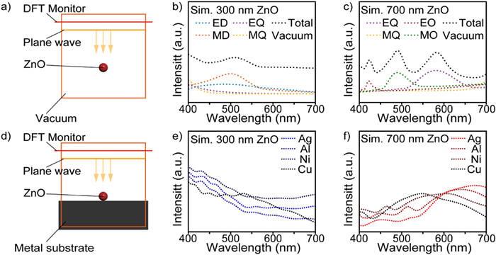
(a) Schematic diagram of FDTD-simulation of a single ZnO sphere in a vacuum environment. (b) FDTD-simulated reflection spectra of a single ZnO sphere with 300 nm diameters in a vacuum environment. (c) FDTD-simulated reflection spectra of a single 700 ZnO sphere in a vacuum environment. (d) Schematic diagram of FDTD-Simulation of a single ZnO sphere on different metal substrates. (e) FDTD-simulated reflection spectra of a single 300 nm ZnO sphere on different metal substrates. (f) FDTD-simulated reflection spectra of a single 700 nm ZnO sphere on different metal substrates.
According to the simulated results (Fig. 1b), for the 300 nm single sphere, the electric dipole (ED) and magnetic dipole (MD) have the main contribution to the scattering peaks in the visible region. For the 700 nm sphere, the electric quadrupole (EQ), electric octupole (EO), and magnetic octupole (MO) have the main contribution to the scattering peaks in the visible region (Fig. 1c). To further confirm the coupling effects between Mie scattering of ZnO spheres and metal substrates, we simulated the spectra for 300 nm and 700 nm ZnO spheres with a series of metal substrates counting Ag, Cu, Ni and Al (Figs. 1d–f). Total scattering peaks of 300 nm ZnO spheres with different metal substrates are very close to each other (Fig. 1e), which means that the appearance of Mie structural colors is similar and it is not conducive to distinguishing different metal substrates. The total scattering peaks of 700 nm sphere with different substrates have obvious differences both in intensity and peak position, which make rapid visual identification of silver ornament possible (Fig. 1f). The mechanism behind the redshift of the Mie resonance scattering peaks of ZnO sphere was the introduction of a metal substrate affected the electric resonance of the ZnO sphere. According to the literature, the redshift degree of Mie scattering peaks would be impacted by space medium drastically [31].
To verify the simulated results, 300 nm and 700 nm ZnO spheres were prepared by wet chemical method (Fig. S2 in Supporting information). The ZnO spheres were synthesized by wet chemical method in the presence of PVP as a templating agent and anhydrous ethanol as solvent. Oriented aggregation of ZnO building blocks embedded in a polymer matrix in which nucleation and growth take place (Fig. S3 in Supporting information). The Scanning electron microscope (SEM) images indicated that the obtained ZnO spheres have uniform morphology and all the products have a narrow diameter distribution, indicating that these spheres have good monodispersity. Transmission electron microscopy (TEM) shows that the synthesized ZnO spheres were polycrystalline aggregates (Fig. S4 in Supporting information). All these spheres are composed of densely packed particle building blocks with a size of the order of tens of nanometers, as also confirmed by the SEM images. Thus, the surface roughness (SR) is estimated to be much lower than the wavelength in the visible range (SR ≈ λ/50), therefore, the surface of these spheres can be considered as smooth, with negligible influence on the Mie scattering features. Furthermore, the XRD pattern (Fig. S4) reveals that ZnO spheres have a pure wurtzite phase (PDF #36-1451).
The synthesized spheres were dispersed in ethanol (1 wt% 50 µL) and used as paint for generating Mie scattering structural colors by spraying method. The different metal substrates with a size of 2.5 cm × 2.5 cm were used to prove the real color generation capability of these spheres based on Mie scattering (Fig. S5 in Supporting information). According to the digital photos and measured reflection spectra of the prepared 300 nm ZnO films (Figs. 2a–h), it can be seen that with the change of metal substrate, the Mie resonance spectra are similar to each other and the Mie structural colors are all in blue appearance, which is highly consistent with the simulated results (Fig. 1b). It is proved theoretically and practically that Mie scattering peaks coupling with different metal substrates caused by 300 nm ZnO spheres have no obvious difference. Based on the digital photos and reflection spectra of the prepared 700 nm ZnO films (Figs. 2i–p), it can be seen that the Mie resonance spectrum clearly differs from each other when ZnO spheres deposit on different metal substrates. As results, the structural colors of 700 nm ZnO spheres sprayed on Ag, Cu, Ni and Al surfaces are red, green, yellow and yellow respectively. Significant color differences allow for rapid identification of different metal surfaces. It should be pointed out that the light source is natural light and the observation angle is not limited.
Figure 2
Figure 2.
(a–h) Digital photos and experimental reflection spectra of structural color films of ZnO spheres with 300 nm diameters on different metal substrates. (i–p) Digital photos and experimental reflection spectra of structural color films of ZnO spheres with 700 nm diameters on different metal substrates (Scale bar = 1 cm).
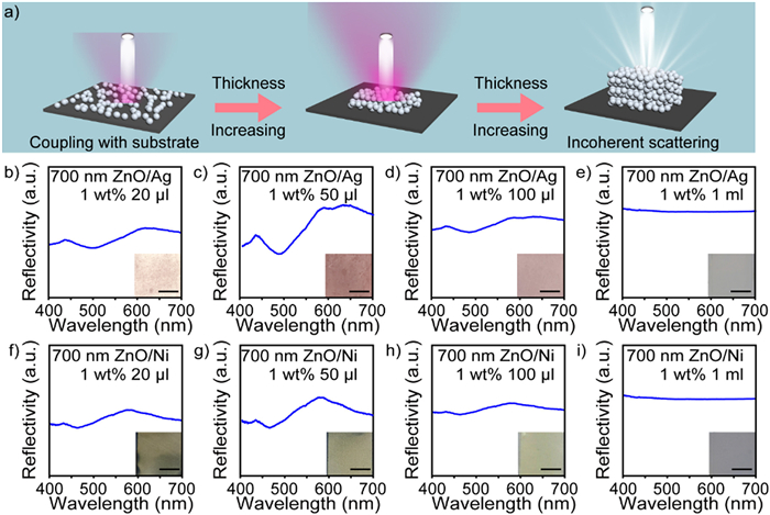
The coherent scatter of the characteristic wavelength is not prominent because the scattering effect with the increase of the spheres on light is relatively strong, which may result in a large drop in color saturation and produce a whitish color or no structural color. Therefore, the aggregation degree of spheres on the substrate surface and the layer thickness of spheres play a crucial role in the detection limits of visual identification (Fig. 3a). The 700 nm ZnO spheres were dispersed in ethanol (1 wt%) and different amounts of dispersions were used as paint for generating Mie scattering structural colors by spraying method. The Ag and Ni substrates with a size of 2.5 cm × 2.5 cm were used to prepare structural color films. Analysis by the digital photos and the corresponding reflection spectrum, the intensity of the scattering spectrum first enhanced and then decreased with the increase of the amount of dispersion solution, whether on the Ag substrate or Ni substrate (Figs. 3b–i). The structural colored substrate prepared with different amounts of dispersion solution was characterized by cross-sectional SEM (Fig. S6 in Supporting information). When the spraying amount of dispersion solution was 20 µL, there were only 1, 2 layers of ZnO spheres, and when the spraying amount of dispersion solution was increased to 50 µL, the structural color film was composed of 2, 3 layers of ZnO spheres, and the color of the structural colored substrate was the brightest. When the amount of dispersion reached 1 ml, the structural color became pale. Too thin or too thick of ZnO spheres will reduce the contrasts in the reflection spectra, producing blackish or whitish colors. After calculation, the optimal dispersion liquid dosage is 50 µL (1 wt%)/6.25 cm2. Identification of one square meter only needs about 0.8 g ZnO spheres which means that the cost of this method is very low. Beside, the uniformity of the spheres had a significant effect on the properties of Mie structural colors. To confirm the minimum standard for the size uniformity of ZnO spheres required, we mixed different amounts of 600 nm ZnO spheres with 700 nm ZnO spheres. As shown in Fig. S7 (Supporting information), the experimental results showed that the peak intensity of Mie structural color decreased obviously when the content of 600 nm spheres exceeds 20%. It was proved that this method required high uniformity of ZnO spheres.
Figure 3
Figure 3.
(a) Schematic diagram of the scattering effect with the increase of the spheres. (b–e) Experimental reflection spectra and digital photos of structural color films of ZnO spheres with 700 nm diameters on Ag substrates. (f–i) Experimental reflection spectra and digital photos of structural color films of ZnO spheres with 700 nm diameters on Ni substrates (Scale bar = 1 cm).
Although the spray gun method is not complicated, this method still requires technical equipment such as spray guns and air pumps, which has a great impact on the convenience of identification. Therefore, we used a portable and dainty atomizer method for testing. The fabrication process of structural colored coatings by atomization deposition is schematically illustrated in Fig. 4a. An ethanol ZnO sphere dispersion with an appropriate amount of Sodium dodecyl sulfate (SDS) as the additive was filled into an atomizer. The nebulizer uses pressure difference to push liquids out through the filter mesh to generate an aerosol. The reason for the lower dispersion concentration (0.5 wt%) and the addition of SDS (0.05 wt%) is to reduce the rate of dispersion settlement which makes it more convenient to use in daily life. In order to prove the stability of the dispersion solution, we left the solution for a week, and the solution did not settle significantly (Fig. S8 in Supporting information). As shown in Figs. 4b and c, the atomizer detector was used to spray on the surface of real and fake silver ornament three times respectively. The real silver coin shows a red Mie structural color and the fake Cupronickel paperweight shows a yellow Mie structural color. The large color difference of appearance makes visual identification easy to be observed. The corresponding reflection spectra proved this conclusion (Figs. 4d and e). To confirm the repeatability of the visual identification method, 700 nm ZnO spheres were used to prepare films for 4 times. As shown in Fig. S9 (Supporting information), all films had a similar red appearance, which proved that the method has good repeatability. Further, we test the angle dependence of the obtained structural colors film, the structural color changed slightly as the viewing angle changed, keeping a red appearance (Fig. S10 in Supporting information). Similarly, to confirm the robustness of the visual identification method, different light and temperature settings were used. As shown in Fig. S11 (Supporting information), all films had a similar red appearance which proved that the method had good robustness. Due to the mild chemical properties of ZnO, covering and erasing the spheres would not cause corrosion or damage to the surface of the ornament. Depth of field microscope tests confirmed this conclusion (Fig. S12 in Supporting information). Reflection spectra and digital photographs prove the above conclusion (Fig. 4d). In daily life, some silver jewelry was silver-plated products. To determine the effect of silver thickness, we simulated the Mie scattering peaks with different thicknesses of Ag. When the thickness of silver was greater than 2 µm, the Mie structural color exhibited similar properties (Fig. S13 in Supporting information). The actual thickness of silver plating was usually 0.1–5 µm, and this method could identify some thin silver plating products. However, when the thickness of silver exceeded a certain degree, this method was difficult to identify it. Further, other testing methods for silver ornaments, such as X-ray fluorescence spectroscopy or surface-enhanced Raman spectroscopy were better than this job in terms of sensitivity and specificity. However, the method reported in this work was visual and did not rely on the large equipment. In terms of economy and ease of use, this method had advantages in daily environments.
Figure 4
Figure 4.
(a) Scheme for visual identification by spray method using atomizer. (b) Digital photographs of Mie colored real Ag coin fabricated by spray method using atomizer. (c) Digital photographs of Mie colored fake Cupronickel paperweight fabricated by spray method using atomizer. (d) Corresponding reflection spectrum of Mie colored real Ag coin. (e) Corresponding reflection spectrum of fake Cupronickel paperweight.
In summary, a rapid visual identification of silver ornament was proposed by the coupling effect between Mie scattering of ZnO dielectric spheres and substrates. A red structural color was shown on the surface of the real silver ornament and a yellow-green structural color was shown on the surface of the cupronickel (fake silver) ornament. The color difference was caused by the different coupling effects between Mie scattering of ZnO spheres and metal substrates. The observation of color does not rely on additional light source equipment, which was convenient for identification. The preparation of ZnO spheres by wet chemical method was simple and the identification required only 0.8 g spheres per square meter which meant the low cost of the identification method. Due to the mild chemical properties of the ZnO, covering and erasing ZnO spheres on the surface of silver would not corrode the silver ornament. This work provided an original method for the identification of silver and facilitated its applications in the field of visual identification.
Declaration of competing interest
The authors declare that they have no known competing financial interests or personal relationships that could have appeared to influence the work reported in this paper.
Acknowledgments
This work was financially supported by the National Natural Science Foundation of China (Nos. 22178047 and 21878042), the Dalian Science and Technology Innovation Fund (No. 2020JJ26GX046), the Fundamental Research Funds for the Central Universities (Nos. DUT22LAB610 and DUT2022TB10).
Supplementary materials
Supplementary material associated with this article can be found, in the online version, at doi:10.1016/j.cclet.2023.109350.
[1]
H. Schiff, Z.N. der Harnsäure, Justus Liebigs Ann. Chem. 109 (1859) 65–71. doi: 10.1002/jlac.18591090107
[2]
R.W. Meikle, Nature 196 (1962) 61.
[3]
C.J.A. Campos, G. Goblick, R. Lee, K. Wittamore, D.N. Lees, Water Res. 124 (2017) 556–565. doi: 10.1016/j.watres.2017.08.021
[4]
S. Wan, B. Torkashvand, T. Häber, R. Suntz, O. Deutschmann, Appl. Catal. B: Environ. 264 (2020) 118473. doi: 10.1016/j.apcatb.2019.118473
[5]
S. Chu, H. Wang, X. Ling, et al., ACS Appl. Mater. Interfaces 12 (2020) 12962–12971. doi: 10.1021/acsami.9b20458
Figure 1
(a) Schematic diagram of FDTD-simulation of a single ZnO sphere in a vacuum environment. (b) FDTD-simulated reflection spectra of a single ZnO sphere with 300 nm diameters in a vacuum environment. (c) FDTD-simulated reflection spectra of a single 700 ZnO sphere in a vacuum environment. (d) Schematic diagram of FDTD-Simulation of a single ZnO sphere on different metal substrates. (e) FDTD-simulated reflection spectra of a single 300 nm ZnO sphere on different metal substrates. (f) FDTD-simulated reflection spectra of a single 700 nm ZnO sphere on different metal substrates.
Figure 2
(a–h) Digital photos and experimental reflection spectra of structural color films of ZnO spheres with 300 nm diameters on different metal substrates. (i–p) Digital photos and experimental reflection spectra of structural color films of ZnO spheres with 700 nm diameters on different metal substrates (Scale bar = 1 cm).
Figure 3
(a) Schematic diagram of the scattering effect with the increase of the spheres. (b–e) Experimental reflection spectra and digital photos of structural color films of ZnO spheres with 700 nm diameters on Ag substrates. (f–i) Experimental reflection spectra and digital photos of structural color films of ZnO spheres with 700 nm diameters on Ni substrates (Scale bar = 1 cm).
Figure 4
(a) Scheme for visual identification by spray method using atomizer. (b) Digital photographs of Mie colored real Ag coin fabricated by spray method using atomizer. (c) Digital photographs of Mie colored fake Cupronickel paperweight fabricated by spray method using atomizer. (d) Corresponding reflection spectrum of Mie colored real Ag coin. (e) Corresponding reflection spectrum of fake Cupronickel paperweight.

 DownLoad:


 下载:
下载:


 下载:
下载:
