College of Electronic and Optical Engineering and College of Flexible Electronics (Future Technology), Nanjing University of Posts and Telecommunications, Nanjing 210023, China
b.
Laboratory for Biomaterials and Drug Delivery, Department of Anesthesiology, Division of Critical Care Medicine, Boston Children's Hospital, Harvard Medical School, Boston, MA 02115, United States
bchen@njupt.edu.cn (B. Chen). 1 These authors contributed equally to this work.
Received Date:
15 September 2023 Accepted Date:
31 October 2023 Revised Date:
07 October 2023 Available Online:
15 September 2024
Abstract:
X-ray detection plays a crucial role across various aspects of our daily lives, encompassing medical diagnoses, security screenings, and non-destructive examinations in industrial settings. Given the wide array of application contexts, a wealth of opportunities is entailed with the practical utilization of both organic and inorganic X-ray detection materials. A novel and promising contender in this realm is the emergence of metal-free organic halide perovskites (O-PVSKs), offering great opportunities and tremendous potential in X-ray detection. This potential can be attributed to the distinct crystalline configuration of O-PVSKs, where organic constituents are structured into an ABX3 perovskite arrangement. Consequently, O-PVSKs exhibit captivating characteristics reminiscent of organic materials, such as lightweight nature and modifiability, all while retaining the distinctive traits associated with halide perovskites ranging from diverse structures to tunable optoelectronic properties. This review article delves into the intrinsic attributes of O-PVSKs and critically examines the viability of O-PVSKs in X-ray detection, through which key features that distinguish O-PVSKs from traditional organic semiconductors and perovskites are outlined. This is followed by a perspective given on their future avenues for exploration.
In recent years, halide perovskites have witnessed unprecedented success in various optoelectronic applications, such as solar cells [1–4], light-emitting diodes [5–8], and photodetectors [9–12]. Such success is attributed to their excellent optical and electrical properties, including high absorption coefficient, tunable bandgap, long carrier lifetime, decent mobility, and defect-tolerant nature. Amid the wider perovskite fever, perovskites also revitalize the stagnant research of X-ray detection materials, enlightening the prospect of advancing the X-ray imaging technology to peek deep into matters with ultrahigh fineness [13–15]. Interestingly, perovskites with intriguing optoelectronic properties encoded in their diverse crystal structures can either directly convert X-ray to electrical signals or indirectly convert X-ray to visible light (known as scintillation). By contrast, the direct-conversion mode free of photodetector arrays can completely circumvent the deleterious light scattering. These attributes entail direct-conversion X-ray detectors with distinct advantages in simple device configuration and high imaging resolution, which are now gaining intensive attention worldwide [16].
As is known, halide perovskites are of high carrier mobility-lifetime product and solution processability on top of their defect-tolerant nature. These characteristics facilitate efficient carrier extraction from the thick perovskites and enable low-cost material fabrication. To date, an overwhelming majority of research efforts have been devoted to exploring the potential of the prevalent all-inorganic perovskites (e.g., CsPbBr3 [17], CsPbBrI2 [18], Cs3Bi2I9 [19]) and organic-inorganic hybrid perovskites (e.g., MAPbI3 [20–22], PEA2PbI4 [23], MA3Bi2I9 [24,25]) in direct X-ray detection. Despite impressive progress made in improving the sensitivity whilst lowering the dark current, these metal halide perovskites (M-PVSKs) are naturally less suitable for application scenarios where lightweight and environmental friendliness are required, such as X-ray detection in space and biocompatible X-ray imaging devices [26].
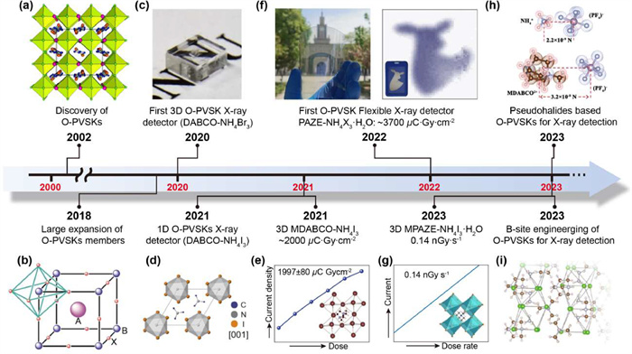
In this context, metal-free organic perovskites (O-PVSKs) come to the scene. Although the discovery of O-PVSKs can be traced back to 2002, their application in X-ray detection has only taken the spotlight since 2020 (Fig. 1) [27–35]. Through sequencing organic components into a perovskite (ABX3) structure, this new class of materials not only retains the key attributes of perovskites (e.g., structure diversity and optoelectronic property tunability) but also is conferred with attractive features of organic materials (e.g., lightweight, eco-friendly). This lends O-PVSKs distinct advantages against M-PVSKs and organic semiconductors and fuels the innovation of next-generation lightweight X-ray detectors.
Figure 1
Figure 1.
Timeline of achievements in the development of O-PVSKs materials and their X-ray detection applications. (a) The discovery of O-PVSK. Reproduced with permission [27]. Copyright 2002, American Chemical Society. (b) The expansion of O-PVSK members. Reproduced with permission [28]. Copyright 2018, The Authors, exclusive licensee AAAS. (c) The first 3D DABCO—NH4Br3 X-ray detector. Reproduced with permission [29]. Copyright 2020, Wiley-VCH. (d) The first 1D DABCO—NH4I3 X-ray detector. Reproduced with permission [30], Copyright 2021, Cell Press. (e) X-ray detection with a sensitivity of -2000 µC Gyair−1 cm−2 based on MDABCO—NH4I3. Reproduced with permission [31]. Copyright 2021, Wiley-VCH. (f) The first flexible X-ray detector based on PAZE-NH4X3·H2O with a record sensitivity of -3700 µC Gyair−1 cm−2. Reproduced with permission [32]. Copyright 2022, Wiley-VCH. (g) X-ray detection with a record LoD of -0.14 nGy/s based on MPAZE-NH4X3·H2O. Reproduced with permission [33]. Copyright 2023, Wiley-VCH. (h) Pseudohalide based MDABCO—NH4(PF6)3. Reproduced with permission [34]. Copyright 2023, Wiley-VCH. (i) B-site engineering of DABCO—N2H5-X3. Reproduced with permission [35]. Copyright 2023, Wiley-VCH.
Till now, there are few review papers dedicated to O-PVSKs. For example, instead of providing overall insights into the intrinsic physicochemical properties (e.g., ferroelectricity, piezoelectricity, charge transport properties, nonlinear optical properties) and highlighting the potential of O-PVSKs in various applications [36–38], Wu et al. made the first attempt to focus on the O-PVSKs targeting X-ray detection, with an emphasis placed on different O-PVSKs obtained by A/B/X-site engineering [39]. Although it reveals the potential of O-PVSKs in X-ray detection, it does not establish the connections between these intrinsic properties and the actual performance of O-PVSKs in X-ray detection. To fill such a research gap, herein, a critical assessment is provided on the emerging O-PVSKs and their potential in X-ray detection. It starts with a brief introduction to the chemical/structural diversity of O-PVSK enabled by site-engineering. Then, the growth methods for both single-crystalline and polycrystalline O-PVSKs are disserted. This is followed by commentaries on the intrinsic properties of O-PVSKs governing the X-ray detection performance. Finally, key features that distinguish O-PVSKs from traditional organic semiconductors and perovskites are highlighted, along with a perspective given on their future developments.
2.
Chemical/structural diversity of O-PVSK
Fig. 2a shows a typical crystal structure of a metal-free organic perovskite (O-PVSK), which adopts a general chemical formula of ABX3. Akin to M-PVSKs, the X-sites of O-PVSKs are occupied by halide (I, Br, and Cl) anions. Yet, the A-sites and B-sites in M-PVSKs and O-PVSKs are rather different. To be specific, in O-PVSKs, the A-site cations are divalent (e.g., C6N2H142+, C4H12N22+), whereas that of the MHP are monovalent (e.g., Cs+, CH3NH2+). More counterintuitively, the B-sites, commonly accommodating only metal cations, are filled by ammonium-based cations (e.g., NH4+, NH3OH+). Such striking features differentiate O-PVSKs from traditional organic semiconductors and the well-known M-PVSKs, opening avenues for the innovation of sensitive and lightweight X-ray detectors.
Figure 2
Figure 2.
Typical crystal structure of O-PVSKs. (a) The chemical/structural diversity of O-PVSKs. (b) The structural transition of DABCO—NH4X3 enabled by site engineering. Reproduced with permission [28]. Copyright 2018, The Authors, exclusive licensee AAAS. (c) Schematic illustration of hydrogen bonding in O-PVSKs. Reproduced with permission [33]. Copyright 2023, Wiley-VCH.
The first report of O-PVSKs was carried out by Harrison et al., who synthesized two brand-new crystals of PAZE-NH4Cl3·H2O (PAZE2+ = C4H12N22+) and DABCO—NH4Cl3 (DABCO2+ = C6N2H142+) [27]. Although the two crystals both adopt a chemical formula of ABX3, the connectivity of [NH4Cl6]2− octahedra differs vastly from each other. Specifically, when the A-site is PAZE2+, the [NH4Cl6]2− octahedra are corner-shared to from a 3D network with water molecules occupying a square position in the (001) plane and voids filled by PAZE2+. By contrast, in DABCO—NH4Cl3, the face-shared [NH4Cl6]2− octahedra form infinite 1D columns, which are interspersed by stacks of DABCO2+ cations. A similar structural transition also occurs upon X-site variation. As illustrated in Fig. 2b [28], when Cl− is replaced by Br−, the crystal structure is converted from 1D hexagonal for DABCO—NH4Cl3 to 3D cubic for DABCO—NH4Br3 [30]. However, it is surprising to note that by using I− with an even larger size, the crystal structure of DABCO—NH4I3 turns back to 1D hexagonal. These observations go against the theoretical prediction from the Goldschmidt tolerance factor since the tolerance factor of DABCO—NH4X3 (X = Cl, Br, I) all falls into the range of 0.87 to 0.89, which should have been a 3D cubic structure [39,40]. This is probably because of the non-spheric geometry of organic cations and the formation of hydrogen bonds of NNH4–H···X and the NDABCO–H···X in DABCO—NH4X3 (Fig. 2c) [13,33]. These primary attempts reveal that the molecular packing in the O-PVSK crystals is affected by site-engineering and hydrogen bonding.
Till now, various kinds of O-PVSKs have been developed by site engineering [36]. Benefiting from the organic nature, the size, geometry and functional group of A-site cations are highly tailorable and designable, which to a large extent contributes to the structural diversity of O-PVSKs. In addition, the exploration of B-site cations and X-site anions further enriches the family of O-PVSKs. For example, Shang et al. and Song et al. recently demonstrated that in addition to classic NH4+, other cations such as N2H5+ and NH3OH+, can also be fitted into B-site of O-PVSKs [41,42]. Notably, the as-formed DABCO—N2H5Br3 has a 1D crystal structure due to the large size of N2H5+ and low electron repulsion of N atoms in the 1D structure with face-sharing octahedra [42]. Besides, compared to commonly reported NH4+-based O-PVSKs, the hydrogen bonding in N2H5+-based counterparts is strengthened, leading to suppressed ion migration, and enhanced chemical stability [35]. Similarly, except traditional halogens (e.g., Cl, Br, I), pseudohalide anions including PF6−, BF4−, SCN− ClO4−, etc. can be exploited to design new O-PVSKs [43–46]. Recently, Jin et al. reported a O-PVSK of MDABCO—NH4(PF6)3 (MDBACO = methyl-N-diazabicyclo[2.2.2]octonium) by using a strongly electronegative PF6− pseudohalide anion. Interestingly, the substitution of I− with PF6− (radius: 220 pm) possessing a larger radius of 255 pm does not change the 3D crystal structure of MDABCO—NH4I3 [47], but the structural rigidity and optoelectronic properties (e.g., electronic band, ionic migration) are greatly improved [34], as discussed later. Given the structural diversity revealed by site-engineering and the remarkable tunability of organic components, one can foresee that O-PVSKs with novel structures and intriguing optoelectronic properties will be flourishing soon.
3.
Preparation of O-PVSKs
The preparation of O-PVSKs is different from both M-PSVKs and traditional organic semiconductors. As is known, the synthesis of M-PVSKs usually involves harsh conditions (e.g., glovebox) and polar aprotic solvents (e.g., N,N-dimethyl formamide) [48–50], while organic semiconductors are best processed by nonpolar solvents such as toluene [13]. Notably, most of these organic solvents are not only toxic but also need to be anhydrous, which impedes their green and low-cost production. By contrast, O-PVSKs are water processible, since in O-PVSKs, organic components are ions fitted to a ABX3 structure. To date, the reported O-PVSKs are mainly in the form of single crystal, which is prepared by either a solvent evaporation method with a fixed temperature or a delicately controlled cooling process, as discussed below.
As a typical example, the first metal-free perovskite PAZE-NH4Cl3·H2O single crystal was spontaneously formed by mixing piperazine hexahydrate and NH4Cl in a aqueous solution and leaving the solution to evaporate at room temperature [27]. The universality of this solvent evaporation method was further validated by the successful synthesis of 23 kinds of O-PVSKs [28]. Of note, in this method, the temperature and initial concentration of the reactants are critical to crystal nucleation. For example, when a high temperature (-60 ℃) was applied to drive solvent evaporation, many small single crystals of MPAZE-NH4I3·H2O were formed due to excessive nucleation [33]. Similarly, a saturated solution (> 0.5 g/mL) of MDABCO—NH4I3, even at room temperature, led to excessive nucleation, subsequently with the formation of many small crystals. In this context, the precursor solution was diluted to 0.2–0.3 g/mL, and after 15 days' evaporation, only a few nuclei were formed. These nuclei continued to grow without the appearance of any new nuclei, giving rise to large crystals [31].
However, in the solvent evaporation method, excessive nucleation, though largely suppressed, is still present. Recently, Song et al. developed a delicately controlled cooling process based on the understanding of temperature-dependent solubility of DABCO—NH4Br3. Instead of precursor salts, DABCO—NH4Br3 powders were first obtained from a typical solvent evaporation method and adopted as the raw material [29]. Prior to the crystal growth, temperature-dependent solubility of DABCO—NH4Br3 powders was investigated. It showed that there was a critical temperature (60 ℃), below which DABCO—NH4Br3 precipitated at a slow rate, as evidenced by the first-order derivative of the solubility, with 6.3 × 10⁻⁵ and 21.3 × 10⁻⁵ g mL−1 K−1 at 25 to 60 ℃ and 60 to 90 ℃, respectively. Considering that a slow precipitation rate corresponds to a slow crystal growth rate and hence a higher crystal quality [51,52], the temperature range of 60–25 ℃ was used for crystal growth. Moreover, the cooling rate during the crystal growth was found to be pivotal. Specifically, with a cooling rate as fast as -10 ℃/h, an opaque and large crystal, in conjunction with some small crystals, were harvested. The small crystals were again due to excessive nucleation, whereas the opacity of the large crystal suggested the existence of abundant defects [53], which was as a result of rapid crystal growth. By contrast, when the cooling rate was slowed down to 0.33 ℃/h, only a transparent and large crystal (5 × 5 × 2 mm3) was formed [29].
Fig. 3 illustrates O-PVSK single crystal growth in the two methods, and the key to growing large-size single crystals is to control the oversaturation to the extent at which excessive crystal nucleation is excluded whilst the crystal growth continues. To do so, once the crystal nucleates, the reactant concentration, determined by the amounts of reactant precipitated from solution and that consumed for crystal growth, must be well controlled below the supersaturation curve but above the saturation curve. Therefore, to rationalize the growth of O-PVSK single crystals, it is imperative to gain a thorough understanding on their temperature-dependent solubility and minimum concentration for homogenous nucleation [52].
Figure 3
Figure 3.
Schematic illustration of the single crystal growth of O-PVSK. Insets: a photograph of MPAZE-NH4I3·H2O obtained by a solvent evaporation method. Reproduced with permission [33]. Copyright 2023, Wiley-VCH. A photograph of DABCO—NH4Br3 grown from a controlled cooling process. Reproduced with permission [29]. Copyright 2020, Wiley-VCH.
In addition to single crystals, polycrystalline O-PVSK films that can be readily made into large area are more feasible for their practical use [14]. Unfortunately, research in this regard remains scarce. Recently, Li et al. adopted a facile one-step spin-coating method to prepare a polycrystalline thin film of PAZE-NH4Br3·H2O [32]. Note that the resultant film was of a thickness of 1.79 µm, far below the thickness required for sufficient X-ray attenuation. To this end, Li et al. further reported a 170-µm-thick MPAZE-NH4I3·H2O-polyvinyl alcohol (PVA) composite films. This composite film was prepared by drop-casting a mixture containing MPAZE-NH4I3·H2O powders and a PVA gel (loading ratio: 33 wt%) [33]. At present, preparing thick and high-quality polycrystalline O-PVSK films over a large area is in great demand. On one hand, the preparation of polycrystalline O-PVSKs should move from lab-scale techniques (e.g., spin-coating) to scalable ones such as doctor blading, slot-die coating, and spray deposition. On the other hand, the preparation needs to be rationalized through in-depth understanding and then delicate control over the intricate nucleation-growth processes of polycrystalline O-PVSK at different conditions. Several parameters such as solvent, atmosphere, temperature, and substrate profoundly affect the nucleation density, nucleation site distribution, intermediate phase transition, and crystal growth rate, thus determining the film coverage as well as the crystallinity [54–57]. In addition, lessons can be learned from the preparation of polycrystalline M-PSVKs films targeting X-ray detection. In particular, the synthetic protocols recently tailor-made for M-PVSKs, including perovskite-filled membrane [58], aerosol-liquid-solid process [18,59], and mechanical sintering [60], are worthy to be explored for O-PVSKs.
4.
Intrinsic properties of O-PVSKs
4.1
X-ray attenuation capability
Sufficient X-ray attenuation is a prerequisite for efficient X-ray detection, and the energies of X-ray photons of general interests are below 120 keV, where photoelectric absorption dominates. As for photoelectric absorption, the coefficient of a material is proportional to Zeff4/Eph3, where Zeff is the effective atomic number [61], and Eph is the energy of incident X-ray photons. Owing to the relatively large atomic number (Z) of halide anions and low Z of organic components, the attention ability of O-PVSKs is superior to traditional organic semiconductors but inferior to M-PVSKs containing heavy metals (e.g., Pb or Bi). For example, according to the photon cross-section database, the absorption coefficient of DABCO—NH4Br3 for 40 keV X-ray photons is 1.0 × 10⁻³ µm−1, which is orders of magnitude larger than that of 4-hydroxycyanobenzene (2.4 × 10⁻⁵ µm−1) but much smaller than that of CsPbBr3 (6.1 × 10⁻³ µm−1). As such, a 2-mm-thick DABCO—NH4Br3 and 4-hydroxycyanobenzene (4HCB) attenuates 87% and 4.8% of 40 keV X-ray photons, respectively [29], whereas that of a 400-µm CsPbBr3 reaches 91.4% [14]. Hence, for efficient X-ray detection, O-PVSKs with mm-scale thickness are necessary.
4.2
Electronic band structures
Electronic band structure is vital since it is highly associated with carrier generation during X-ray detection. As a simple example, the number of electron-hole pairs (β) per X-ray photon excited in an O-PVSK is determined by the equation [62],
(1)
where Eph is the energy of X-ray photon, and Eg is the bandgap. It suggests that narrowing the bandgap leads to efficient carrier excitation, which is favorable for affording a high sensitivity. However, a small bandgap tends to give rise to a high intrinsic carrier concentration, resulting in a large dark current, which is considered a pressing issue for most perovskite X-ray detectors [15,63]. Such a dilemma induced by the bandgap should be carefully considered for O-PVSKs.
Different from M-PVSKs whose electronic band structure mainly originates from the [BX3]− network [64], the electronic band structure of O-PVSKs is dominated by A-site and X-site (Fig. 4a) [13]. As calculated from partial density of states (PDOS), the valence band maximum (VBM) of DABCO—NH4Cl3 stems from 3p orbitals of Cl, whereas its conduction band minimum (CBM) is contributed by C states of DABCO2+ and N states of DABCO2+ or NH4+. Evidently, the variation of X-site directly tailors the electronic band structure of O-PVSKs. With decreasing the electronegativity from Cl to Br and I, the conduction and valence bands become increasingly dispersive, indicative of a decreased carrier effective mass and hence an increased mobility [30]. Moreover, this is accompanied with a gradually narrowed bandgap of 5.89, 5.25 and 4.71 eV for DABCO—NH4Cl3, DABCO—NH4Br3 and DABCO—NH4I3. On the contrary, when a strongly electronegative PF6− is used as the X-site, MDABCO—NH4(PF6)3 has a larger bandgap than the I-counterpart (7.1 eV vs. 3.9 eV). PDOS simulation shows that this significantly enlarged bandgap is because that the VBM of MDABCO—NH4(PF6)3 and MDABCO—NH4I3 is contributed by the I-5p orbitals and F-2p orbitals, respectively.
Figure 4
Figure 4.
Intrinsic properties of O-PVSKs. (a) Typical band structures of an O-PVSK and a M-PVSK. (b) Computed band structure and DOS projected onto the components of this perovskite MDABCO—NH4I3. Reproduced under the terms of CC-BY-NC-ND 4.0 license [65]. (c) The calculated bandgap of O-PVSKs based on A2+ cations with different LUMO energies. Reproduced under the terms of CC-BY-NC-ND 4.0 license [65]. (d) The µτ product and bandgap of O-PVSKs.
In addition, the electronic band structure of O-PVSKs regulated by A-site and B-site are investigated. Fig. 4b shows a typical band structure and DOS projected onto the components of MDABCO—NH4I3. The DOS and charge-density distribution clearly validates that the CBM predominately originate from the C and N states of MDABCO2+, while the contribution from the N states of NH4+ is negligible. Moreover, it is predicted that by substituting A-site with different lowest unoccupied molecular orbital (LUMO) energies, the bandgap of O-PVSKs can be tuned in a wide range of 0.8–4.0 eV (Fig. 4c) [65], though experimental verification remains to be done. By contrast, replacing NH4+ with N2H5+ at B-site exerts negligible effects on the electronic structure of O-PVSKs. This is evidenced by DABCO—N2H5Br3, whose VBM and CBM is dominated by Br− and DABCO2+, respectively [35].
Although small-bandgap (< 2 eV) O-PVSKs have been theoretically predicted, the reported O-PVSKs are generally of a bandgap ranging from 4.2 eV to 7.1 eV (Table 1 and Fig. 4d) [19,24,30–35,66–71]. Such a large bandgap confers O-PVSKs a disadvantage against M-PVSKs in terms of carrier excitation. For example, according to Eq. 1, when exposed to a 50 keV X-ray photon, the number of electron-hole pairs excited in DABCO—NH4Br3 is -4200, which is significantly less than that of MAPbI3 (-11,000). Nevertheless, compared to M-PVSKs, the wider-bandgap O-PVSKs enjoy a lower intrinsic carrier concentration and a larger resistivity, which are favorable for affording a smaller dark current. To be specific, the wide-bandgap DABCO—NH4Br3 (5.25 eV) shows an intrinsic carrier concentration (ni) of 7.0 × 109 cm−3 and a bulk resistivity (ρ) of 9.8 × 10⁹ Ω cm [30], superior to that of MAPbI3 (ni = 2 × 10¹⁰, ρ = 1.0 × 10⁸ Ω cm) [72].
Table 1
Table 1.
The intrinsic properties and X-ray detection performance of O-PVSKs.
After carrier excitation, carrier transport in O-PVSKs matters since it determines the proportion of the X-ray excited carriers that is eventually collected. The carrier collection efficiency is determined by carrier mobility (µ), carrier lifetime (τ) and electric field (E), and the Schubweg distance, termed as the product of µτE, corresponds to the average distance the carriers travel before being trapped or recombined [73]. Although increasing the electrical field improves the efficiency of carrier collection, it simultaneously triggers substantial carrier injection, leading to a high dark current. Therefore, a large µτ product is crucial for O-PVSKs to be used for X-ray detection.
Table 1 and Fig. 4d summarized the values of µτ product reported for O-PVSKs. Although the µτ product of O-PVSK single crystals (1 × 10⁻⁴–3 × 10⁻³ cm2/V) is slightly inferior to that of M-PVSKs including 3D MAPbI3 (1.3 × 10⁻² cm2/V) [67] and 0D MA3Bi2I9 (2.9 × 10⁻³ cm2/V) [24], it is at least an order of magnitude higher than that of organic semiconductors (4-HCB: 6.7 × 10⁻⁵ cm2/V) [70] and commercial amorphous selenium (-10−7 cm2/V) [74]. Given that it is desired for X-ray detection material to have a µτ product > 10−4 cm2/V [75], O-PVSKs are entailed with great promise in fabricating next-generation highly sensitive light-weight X-ray detectors.
Notably, compared to O-PVSK SCs, polycrystalline O-PVSKs suffer from a much lower µτ product, with about 1.0 × 10⁻⁶ cm2/V reported for polycrystalline PAZE-NH4X3·H2O (X = Cl, Br and I). Similar phenomenon has also been observed for M-PVSKs [14], which is as a result of much higher defect density (-1015 cm−3) of the films than that of single crystals (-1010 cm−3) (Table 1). It suggests that the carrier transport properties of O-PVSKs are highly dependent on the crystal quality, and particular attention needs to be paid to improving the quality of polycrystalline O-PVSKs.
4.4
Ion migration
Ion migration is a universal phenomenon observed for perovskite materials with an ionic and soft nature [76]. For X-ray detectors operating at external electrical fields, ion migration will not only severely raise the noise signal but also lead to baseline drift [77]. Therefore, the energy barrier of ion migration of O-PVSKs is an important property that needs to be evaluated.
Given that halide anions are the most possible moving ions in traditional M-PVSKs [78], first-principle calculations are performed to simulate the diffusion of Br− anions along the possible migration paths in DABCO-NH4Br3, it turns out that the diffusion barrier of Br− is only slightly higher than that in MAPbBr3 (0.25 eV vs. 0.20 eV) [29]. This is probably because of the weak interactions of ionic and hydrogen bonding despite that the bulky DABCO2+ cations that can physically suppress ion migration [79]. Differently, when using a strongly electronegative PF6− pseudohalide anion to reinforce the overall hydrogen bonding of O-PVSKs, ionic migration induced by the X-sites can be greatly suppressed. This is experimentally validated by the temperature-dependent conductivity measurements, which shows that MDABCO-NH4(PF6)3 has a much higher activation energy for ionic conduction (0.91 eV) as compared to that of MDABCO—NH4I3 (0.60 eV) [34]. As a result, the baseline drift of MDABCO—NH4(PF6)3 and MDABCO-NH4I3 is found to be 1.36 × 10⁻⁷ and 3.35 × 10⁻⁶ nA cm−1 V−1 s−1, respectively, which is orders of magnitude lower than that of 3D MAPbI3 (4.7 × 10⁻⁵ nA cm−1 V−1 s−1) [67]. Such a mitigated ionic migration is also reported for strongly hydrogen-bonded O-PVSKs such as PAZE-NH4X3·H2O and MPAZE-NH4X3·H2O. Specifically, the energy barrier of halide anions to diffuse in PAZE-NH4X3·H2O (X = Cl, Br, I) ranges from 1.39 eV to 1.41 eV [32], which is much higher than that calculated for M-PVSKs (0D MA3Bi2I9: 1.18 eV, 2D (PEA)2PbI4: 0.85 eV and 3D MAPbI3: 0.54 eV) [24]. Similarly, due to the strong hydrogen bonding, MPAZE-NH4I3·H2O shows an obviously enlarged diffusion barrier with respect to MDABCO-NH4I3, offering a record baseline drift of 6.7 × 10⁻⁹ nA cm−1 V−1 s−1 for O-PVSKs [33].
To date, investigations on the ion migration of O-PVSKs are limited to X-site. It appears that compared to 3D M-PVSKs, O-PVSKs with bulky cations at A-sites are advantageous in suppressing the X-site migration. Moreover, the energy barrier of X-site diffusion is profoundly affected by the hydrogen bonding strength of O-PVSKs, and a strengthened hydrogen bonding is conducive to the suppression of X-site migration. Importantly, unlike M-PVSKs whose B-sites are filled by multivalent metal ions such as Pb2+, Bi3+, the B-sites of O-PVSKs are NH4+, which are highly possible to migrate particularly when under an external electrical field. Yet, no investigations have been made to our knowledge to study the B-sites migration in O-PVSKs.
4.5
Mechanical properties
Owing to the organic components and weak intermolecular interactions (e.g., Van der Walls forces and hydrogen bonding), O-PSVKs are touted as more desirable materials for developing flexible X-ray detectors as compared to M-PVSKs [28,29]. However, this is a common misconception, which needs to be clarified. In the following, the mechanical properties of O-PVSKs are scrutinized in comparison with that of M-PVSKs.
In 2019, Ehrenreich et al. made the first investigation on the mechanical properties of MDABCO-NH4I3. The bulk modulus (K), representing the overall strength of chemical bonds within a material, is generally adopted to compare the resistance upon volumetric deformation, as defined by the following equation,
(2)
where V is the unit cell volume, and p is the pressure. Through analyzing the X-ray diffraction data obtained at different pressure, the K of MDABCO-NH4I3 is determined to be 15.19 GPa [80], similar to that of M-PVSKs (e.g., MAPbI3: 14.8 GPa [81], MAPbBr3: 17.6 GPa [82]). Then, nanoindentation measurements were performed to record the load–displacement curves, from which Young's modulus (E) can be extracted according to the Oliver–Pharr model [79]. Notably, the E of MDABCO-NH4I3 (E[111] = 14.7 GPa), corresponding to the resistance to reversible elastic deformation [83], is comparable to M-PVSKs such as MAPbI3 (E[100] = 10.4 GPa), MAPbBr3 (E[100] = 17.7 GPa), and MAPbCl3 (E[100] = 19.8 GPa) [84]. It is worthy to pointing out that E follows the same trend of K, suggesting that the elastic properties of O-PVSK are highly related to the overall strength of the chemical bonds.
Later, Cui et al. comparatively studied the mechanical properties of DABCO-NH4X3 (X = Cl, Br, I) by using the nanoindentation technique. Interestingly, with increasing the electronegativity from I to Cl, the E is determined to be 14.2, 15.8 and 19.8 GPa for the I-, Br- and Cl-counterparts respectively, suggesting that DABCO-NH4I3 has the best elastic recovery ability [30]. Note that the increased electronegativity leads to an enhanced hydrogen bonding, again demonstrating that a tightly bonded O-PVSK tends to have a high E.
In addition to the X-site, the elastic properties of O-PVSKs are also affected by A-sites. For example, by replacing the methyl group of MDABCO with the amino group, NDABCO-NH4Br3 crystal displays an E of 20.7 GPa [79], which is larger than DABCO-NH4Br3 (15.8 GPa). More interestingly, the heavy dependence of E on the crystal planes of O-PVSKs is observed for PAZE-NH4Br3·H2O. To be specific, the E along the (100) plane is as large as 46.2 GPa, whereas that of the (111) plane is 21.0 GPa. Such a vast difference is attributed to the presence of H2O molecules in the (110) plane, which induces more hydrogen bonds [85].
The above investigations suggest that the mechanical properties of O-PVSKs are dominated by the chemical bond strength and crystal packing density, and a relatively loosely bonded O-PVSK is endowed with good mechanical flexibility, though ion migration is facilitated at the same time. Such a trade-off must be carefully considered when deploying O-PVSKs as flexible X-ray detectors. Another unexpected finding is that O-PVSKs held together by hydrogen bonds exhibit comparable crystal stiffness with M-PVSKs constructed by metal coordinate bonds, hence O-PVSKs are considered as soft as M-PSVKs. Yet, a prerequisite for radiation-dose-sensitive applications (e.g., medical imaging) is sufficient X-ray attenuation, while the required thickness of O-PVSKs comes to mm-scale, i.e., 2-mm-thick DABCO-NH4Br3 attenuates 87% of 40 keV X-ray photons. Previous reports indicate that single-crystalline O-PVSKs at such a thickness are rather rigid, which can hardly be made flexible [29]. However, it should be noted that the E of perovskites in single-crystalline and polycrystalline forms is different, as validated by MAPbI3 whose single crystals have an E of 12–27 GPa, which is higher than that of their polycrystalline films (2–20 GPa) [86]. Hence, the flexibility of O-PVSK in polycrystalline forms remains open.
5.
Performance of O-PVSK X-ray detectors
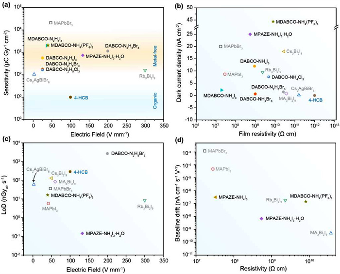
Fig. 5 summarizes the key figures-of-merit of O-PVSK X-ray detectors reported so far, including sensitivity, lowest limit of detection (LoD), dark current density, and baseline drift. Detailed description of these parameters can be found elsewhere [14,87]. Here, we only highlight the achievements made by O-PVSKs, through which one can clearly judge to what extent O-PVSK X-ray detectors have been developed.
Figure 5
Figure 5.
The key figures-of-merit of O-PVSKs X-ray detectors reported so far. (a) Sensitivity; (b) Dark current density; (c) Lowest limit of detection; (d) Baseline drift.
As shown in Fig. 5a, the sensitivity of O-PVSKs is in the range of 102–4 × 10³ µC Gyair−1 cm−2, which is much higher than that of organic 4-HCB (10 µC Gyair−1 cm−2) but inferior to that of M-PVSKs such as MAPbBr3 (2.1 × 10⁴ µC Gyair−1 cm−2). On one hand, it indicates that compared with organic semiconductors, O-PVSKs are more suitable for highly sensitive lightweight X-ray detectors. On the other hand, O-PVSKs has lower Zeff, larger bandgap, and slightly inferior µτ product than M-PVSKs, which puts O-PVSKs at a disadvantage in X-ray attenuation, carrier generation, and transport. Therefore, the moderate sensitivity of O-PVSKs is understandable. However, O-PVSKs still offer at least an order of magnitude higher sensitivity with respect to that of commercial amorphous selenium (20 µC Gyair−1 cm−2) [88], laying a foundation for their practical use.
Despite the great importance of sensitivity, it is necessary to look at dark current density at the same time. It is because the high sensitivity of many perovskite X-ray detectors is achieved by photoconductive gain, that is, multiple majority injection for the electrode [14,89,90]. However, photoconductive gain is accompanied with an undesirably high dark current density, which raises the shot noise level and lowest LoD. More importantly, to ensure a wide dynamic range, the application-specific integrated circuits (ASIC) prevalent in today's flat-panel X-ray detector requires an ultralow dark current density of 1 nA/cm2 [91,92]. It is only until recently the acceptable dark current density has been increased to 100 nA/cm2 due to the improvement of the ASIC layout [93]. Fig. 2b shows that the dark current density of O-PVSK X-ray detectors is on par with that of state-of-the-art M-PVSK counterparts, and a record low dark current density of 0.61 nA/cm2 is reported for DABCO-NH4Br3. Such a low dark current density meets the requirement for O-PVSKs to be integrated with the ASIC.
LoD is another important parameter for X-ray detectors since it directly relates to the minimum dose rate required for effective X-ray detection. For example, an upper limit of LoD (5500 nGyair/s) is commonly set for medical imaging. In principle, lowering down the LoD needs to increase X-ray-generated current and reduce the noise level. Given that X-ray-generated current is proportional to sensitivity, while the noise level, ruled by shot noise, is determined by dark current [15], thus a high sensitivity and a low dark current are desirable. Compared to M-PVSKs, O-PVSKs are of slightly lower sensitivity and comparable dark current. As such, O-PVSKs generally present a LoD inferior to that of state-of-the-art O-PVSKs such as Rb3Bi2I9 (8.3 nGyair/s MAPbI3 (5.7 nGyair/s). Nonetheless, the reported values for most O-PVSKs are less than 500 nGyair/s, far below the upper limits for medical imaging (Fig. 5c).
In addition, baseline drift arising from ion migration in perovskites is critical to reliable signal recording in the long term [21]. Although it has not been extensively studied for O-PVSKs, theoretical calculation shows that the energy barrier of halide migration in strongly hydrogen-bonded O-PVSKs (e.g., PAZE-NH4I3·H2O: 1.41 eV) is even higher than that in 0D M-PVSKs (e.g., MA3Bi2I9: 1.18 eV), let alone 3D M-PVSKs with notorious ion migration (e.g., MAPbI3: 0.54 eV) [24,32]. As shown in Fig. 5d, O-PVSKs exhibit dramatically stabilized baseline as compared to 3D M-PVSKs. However, in terms of baseline drift, 0D MA3Bi2I9 still outperforms that of O-PVSKs. Such a discrepancy suggests that the energy barrier of halide migration itself cannot be regarded as the gold rule to predict the baseline drift behaviors of perovskites. In particular, the migration of monovalent NH4+ (at B-sites of O-PVSKs) might also play an important role in the baseline drift, which needs to be explored soon.
6.
Conclusions and perspective
In conclusion, O-PVSKs present comprehensively balanced high performance, positioning them as a novel class of material for next-generation X-ray detectors. Notably, diverging from traditional organic semiconductors and M-PVSKs, O-PVSKs exhibit the following distinctive traits: (1) While constrained by attributes like low mass density, low Z, and a wide bandgap, O-PVSKs are unable to rival most M-PVSKs in terms of sensitivity. However, due to their commendable µτ product, O-PVSKs generally afford a sensitivity surpassing those of organic semiconductors by orders of magnitude. This signifies that O-PVSK X-ray detectors are not only lightweight but also highly sensitive, potentially finding utility in X-ray astronomy applications. (2) Diverging from the majority of M-PVSKs, prevailing O-PVSKs exhibit a wide-bandgap semiconductor nature (Eg: 4.2 eV to 7.1 eV), rendering them substantially resilient to external stimuli like solar radiation, temperature variations, and more. These unique properties, coupled with their lightweight character, position O-PVSKs as advantageous contenders for portable and solar-blind X-ray detectors, particularly in scenarios necessitating on-site rescue operations or outdoor emergency deployment [94].
Despite the commendable advancements achieved and the promising potential of O-PVSK X-ray detectors, substantial dedication is imperative towards chemical/structural design, crystal/film preparation, mechanistic understanding, and device integration.
To commence, continued material innovation is pivotal to enhance optoelectronic attributes. Achieving this can be realized through targeted site-engineering. Notably, strategic molecular design of the versatile A-site cations holds substantial sway over the structural dimensions, electronic band arrangement, and hydrogen bonding potency within O-PVSKs. In particular, a strengthened hydrogen bonding will lead to a suppressed ion migration, an improved electron-phonon coupling and a prolonged carrier lifetime but a compromised mechanical flexibility [32,33]. As such, it is anticipated that intrinsic traits tied to X-ray detection, encompassing parameters like bandgap, mobility, and energy barriers for ion migration, can be precisely customized for diverse applications.
Secondly, the urgent requirement to produce sufficiently large, thick, and high-quality O-PVSKs is evident. Currently, O-PVSKs predominantly exist as diminutive single crystals. Although the thickness of these single-crystalline O-PVSKs meets the requirement for sufficient X-ray detection (millimeter scale), the small active area makes them unsuitable for most practical applications such as radiography (34 cm × 43 cm). By contrast, polycrystalline O-PVSKs can be readily fabricated across large areas, yet achieving millimeter-scale thickness is not an easy task. Since preparing millimeter-scale-thick polycrystalline films requires a layer-by-layer deposition process with orthogonal solvents, while the precursors of O-PVSKs can only be dissolved in polar solvents. Drawing inspiration from M-PSVKs, lessons can be gleaned. For instance, employing a solution-based lithography-assisted epitaxial growth technique has facilitated the cultivation of single-crystalline MAPbI3 at dimensions of 5 cm × 5 cm [95]. Moreover, innovative methodologies like perovskite-filled membranes [58] and aerosol–liquid–solid processes [18,59] have been formulated, leading to the successful growth of polycrystalline perovskite films with substantial thickness and coverage.
Thirdly, delving deeper into the mechanistic intricacies of emerging O-PVSKs holds pivotal significance. Despite the assembly of various O-PVSKs into X-ray detectors, existing research has yielded limited insights into interfacial energy band alignment. This knowledge gap hampers both rational material design and the concurrent development of corresponding X-ray detectors. Notably, the perplexing observation that O-PVSK single crystals, characterized by wide bandgaps, do not exhibit substantially lower dark currents compared to their small-bandgap M-PVSK counterparts necessitates elucidation. This anomaly suggests that as-grown O-PVSKs cannot be treated solely as intrinsic semiconductors, underscoring the role of self-doped defect states in shaping electronic properties. Addressing this necessitates thorough theoretical and experimental investigations, encompassing a comprehensive elucidation of electronic band structure elements such as CBM-VBM, Fermi level, and defect energy levels.
Lastly, the integration of O-PVSKs with thin-film transistor (TFT) array-based application-specific integrated circuit (ASIC) configurations, along with the rigorous validation of pixel-dense array detectors, represents a tangible stride towards practical utility. Diverging from the single-pixel detectors documented in literature, the signal readout complexities inherent to ASIC-driven array detectors demand simultaneous fulfillment of stringent parameter prerequisites. Furthermore, given the interfacial stresses arising from the disparate mechanical properties of O-PVSKs and the substrate, ensuring persistent electronic connection within the integrated system remains an unaddressed challenge. Pioneering innovative strategies, like the establishment of network topology structures at the interface to induce stress-buffering or alleviation effects, holds promise as a forward-looking research trajectory [20,96].
Declaration of competing interest
The authors declare that they have no known competing financial interests or personal relationships that could have appeared to influence the work reported in this paper.
Acknowledgments
The authors acknowledge the support from the National Natural Science Foundation of China (Nos. 62205154 and 62205155), and the Natural Science Research Start-up Foundation of Recruiting Talents of Nanjing University of Posts and Telecommunications (Nos. NY221112 and NY222104).
J.C. Jolly, B. Jin, L. Jin, et al., Adv. Sci. 10 (2023) 2302475. doi: 10.1002/advs.202302475
Figure 1
Timeline of achievements in the development of O-PVSKs materials and their X-ray detection applications. (a) The discovery of O-PVSK. Reproduced with permission [27]. Copyright 2002, American Chemical Society. (b) The expansion of O-PVSK members. Reproduced with permission [28]. Copyright 2018, The Authors, exclusive licensee AAAS. (c) The first 3D DABCO—NH4Br3 X-ray detector. Reproduced with permission [29]. Copyright 2020, Wiley-VCH. (d) The first 1D DABCO—NH4I3 X-ray detector. Reproduced with permission [30], Copyright 2021, Cell Press. (e) X-ray detection with a sensitivity of -2000 µC Gyair−1 cm−2 based on MDABCO—NH4I3. Reproduced with permission [31]. Copyright 2021, Wiley-VCH. (f) The first flexible X-ray detector based on PAZE-NH4X3·H2O with a record sensitivity of -3700 µC Gyair−1 cm−2. Reproduced with permission [32]. Copyright 2022, Wiley-VCH. (g) X-ray detection with a record LoD of -0.14 nGy/s based on MPAZE-NH4X3·H2O. Reproduced with permission [33]. Copyright 2023, Wiley-VCH. (h) Pseudohalide based MDABCO—NH4(PF6)3. Reproduced with permission [34]. Copyright 2023, Wiley-VCH. (i) B-site engineering of DABCO—N2H5-X3. Reproduced with permission [35]. Copyright 2023, Wiley-VCH.
Figure 2
Typical crystal structure of O-PVSKs. (a) The chemical/structural diversity of O-PVSKs. (b) The structural transition of DABCO—NH4X3 enabled by site engineering. Reproduced with permission [28]. Copyright 2018, The Authors, exclusive licensee AAAS. (c) Schematic illustration of hydrogen bonding in O-PVSKs. Reproduced with permission [33]. Copyright 2023, Wiley-VCH.
Figure 3
Schematic illustration of the single crystal growth of O-PVSK. Insets: a photograph of MPAZE-NH4I3·H2O obtained by a solvent evaporation method. Reproduced with permission [33]. Copyright 2023, Wiley-VCH. A photograph of DABCO—NH4Br3 grown from a controlled cooling process. Reproduced with permission [29]. Copyright 2020, Wiley-VCH.
Figure 4
Intrinsic properties of O-PVSKs. (a) Typical band structures of an O-PVSK and a M-PVSK. (b) Computed band structure and DOS projected onto the components of this perovskite MDABCO—NH4I3. Reproduced under the terms of CC-BY-NC-ND 4.0 license [65]. (c) The calculated bandgap of O-PVSKs based on A2+ cations with different LUMO energies. Reproduced under the terms of CC-BY-NC-ND 4.0 license [65]. (d) The µτ product and bandgap of O-PVSKs.
Figure 5
The key figures-of-merit of O-PVSKs X-ray detectors reported so far. (a) Sensitivity; (b) Dark current density; (c) Lowest limit of detection; (d) Baseline drift.

 DownLoad:


 下载:
下载:


 下载:
下载:
