Scheme 1.
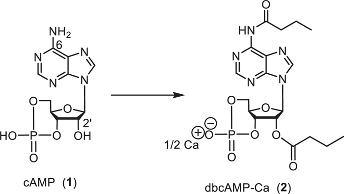
Structure of cyclic adenosine-3′, 5′-monophosphate (1) and calcium dibutyryladenosine cyclophosphate (2).
A sequential continuous flow synthesis and purification process of calcium dibutyryladenosine cyclophosphate
Liming Cao , Maolin Sun , Chaoming Liang , Lei Yang , Yueyue Ma , Ruihua Cheng , Yanxiong Ke , Wei Yu , Jinxing Ye

Adenosine-3′, 5′-cyclic cyclophosphate (Scheme 1, cAMP, 1) is an essential intracellular second messenger controlling the critical cellular functions [1]. The introduction of lipophilic side chains in position N6 and/or 2′-O of cAMP enhances its membrane permeability and overcomes its defect to being easily destructed by cyclic nucleotide phosphodiesterase [2–4]. Calcium dibutyryladenosine cyclophosphate (or calcium N6, 2′-O-dibutyryl cyclic adenosine-3′, 5′-monophosphate. Scheme 1, dbcAMP-Ca, 2), derived from cAMP, is used in the clinical treatment of cardiovascular diseases, such as angina pectoris and acute myocardial infarction [5].
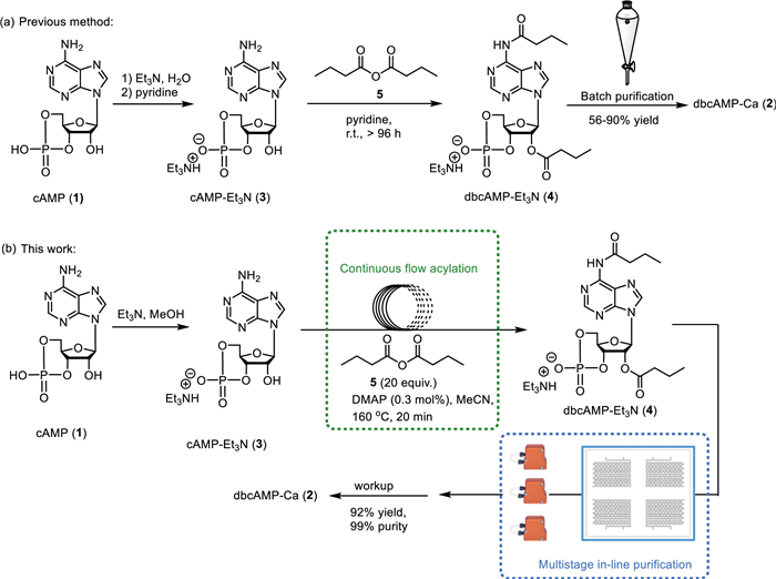
In 1960s, Posternak and co-workers developed a synthesis method for dbcAMP [6–8]. This method typically consisted of three steps, the synthesis of cAMP-Et3N, the acylation reaction, and the purification process (Scheme 2a). It was widely used in industrial production because of the mild conditions and clear reaction mechanism [9–12]. However, this process suffered from the long reaction time (4–10 days) and utilization of pyridine, which is an undesirable solvent in the pharmaceutical industry due to its high toxicity [13]. In addition, tedious extraction and washing were time-consuming and unstable in the purification process, as the prolonged treatment of dbcAMP in aqueous could lead to hydrolysis [9,14]. Therefore, an efficient, robust, and operationally convenient process for the synthesis of dbcAMP-Ca is greatly needed.
In recent years, continuous flow chemistry has become a research hotspot both in academia and industry [15–21]. Compared to the traditional batch synthesis, the continuous flow mode is more reliable and reproducible due to the accurate control of the reaction parameters, such as temperature, pressure, reagent dosage, and residence time [22]. It is also characterized by the fast heat and mass transfer rates, significantly improving the overall safety of the organic synthesis process even under harsh reaction conditions [23,24]. Besides, the scale-up continuous flow process could be achieved rapidly by changing the reactor volume with less process optimization [25,26]. So far, many new continuous flow processes for drug synthesis were developed in decades [27–29].
Herein, we described a sequential continuous flow synthesis and purification process for dbcAMP-Ca (Scheme 2b). By combining the continuous acylation reaction in a coil reactor with the multistage in-line purification based on femtosecond laser-tailored 3D circular cyclone-type micromixer chips, the limitations of long production cycles, large amounts of highly toxic reagents, and unstable yields in traditional batch processes was eliminated.
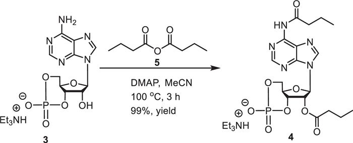
The presence of a tertiary amine was necessary for the acylation reaction [14], and cAMP-Et3N could be easily prepared. Thus cAMP-Et3N was prepared on a large scale as the starting material (see Supporting information for details of the synthesis procedure). Then, the conditions of the acylation reaction were screened in batch (Table S2 in Supporting information). DMAP (4-(N,N-dimethylamino)-pyridine), the effective nucleophilic base for the acylation of amine and alcohols [30,31], could significantly improve the reaction efficiency (Table S2, entry 3). Acetonitrile was used as solvent for the acylation reaction replacing pyridine (Table S2, entry 4 and Table S3 in Supporting information). When 20 equiv. of n-butyric anhydride and 1 mol% DMAP were added, the quantitative conversion was obtained on a 1 mmol scale at 100 ℃ for 3 h (Scheme 3).
In order to further enhance the acylation process, screening of the acylation conditions was carried out in continuous flow (Table 1). A 316L stainless steel coil was used as the flow reactor, with a gas chromatography oven and a back pressure regulator (BPR) to control the temperature and the pressure (Fig. S1 in Supporting information). It was worth noting that premixing cAMP-Et3N, n-butyric anhydride, and DMAP in acetonitrile into a clear solution was necessary to prevent clogging. In the presence of 0.5 mol% DMAP, the conversion was almost quantitative at 140 ℃ with a residence time of 25 min (entries 1 and 2). Increasing the temperature further accelerated the reaction and thus shorten the required residence time (entry 3). Reducing the amount of DMAP to 0.3 mol%, a high yield was obtained as well by increasing the temperature to 160 ℃ with 20 min (entries 4–7). Further reduction in the amount of DMAP to 0.1 mol% lead to reduced conversion (68%, entry 8). When the temperature was increased to 170 ℃, several impurities were generated and the yield decreased to 90% (entry 9). Moreover, a long run of the continuous acylation was carried out to demonstrate the process stability (entry 10). The flow process proceeded smoothly for 5 h with > 99% yield of 4 within the entire period (Table S4 in Supporting information).
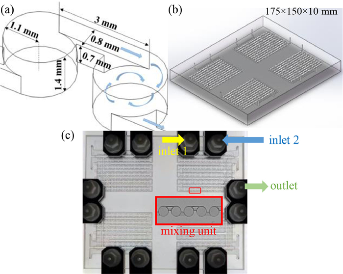
In-line purification is an important tool to handle the unstable intermediates or multi-step sequential synthesis [32], and liquid–liquid continuous extraction is one of the common protocols [17,33–35]. Recently, we designed and fabricated a glass four-module micromixer chip with 3D circular cyclone-type channel using femtosecond laser micromachining (Fig. 1) [36–39]. Multiphase fluids could be fully mixed with high mass transfer efficiency in the millimeter-level 3D cyclone passive microchannel (Fig. 1a). This chip contains four individual modules, and separate temperature control channels were available for each module (Figs. 1b and c), allowing operations to be performed independently in each module. Compared to traditional single-module mixer, this chip has the advantages of being highly efficient, space-saving, and versatile.
Herein, we developed a multistage continuous purification process in the 3D four-module cyclone-type micromixer chip (Fig. S4 in Supporting information). As shown in Fig. 2, the acylation residue was hydrolyzed by H2O in Module Ⅰ, and the desired compound 4 could be extracted into the aqueous phase. MTBE (methyl t–butyl ether) was added to dilute the reaction mixture in Module Ⅰ to avoid blockage and facilitate phase separation (Table S5 in Supporting information for details). Zaiput membrane-based liquid–liquid separators (SEP-10) were used for phase separation. The adjustable BPRs were fitted at appropriate locations to ensure the differential pressure of less than 0.35 MPa at the outlets of the membrane separators [40]. Through Separator Ⅰ, the aqueous phase of Module Ⅰ flew directly into Module Ⅲ, and the organic phase of Module Ⅰ entered Module Ⅱ for the secondary extraction. After adding H2O by Pump D and separating by Separator Ⅱ, the aqueous phase of Module Ⅱ also flew into Module Ⅲ. The combined aqueous solution was acidified by 1 mol/L HCl (adjusted to pH 3–4), washed with extra MTBE to remove the resident fat-soluble impurities, such as n-butyric anhydride and n-butyric acid, and passed through Separator Ⅲ. The aqueous phase of Module Ⅲ was treated with CaHCO3 in batch, followed by concentration and recrystallization to obtain the desired dbcAMP-Ca (2). The second extraction in Module Ⅱ was necessary in this purification process as the yield could be improved effectively (Figs. S2 and S3, Tables S5-S7 in Supporting information). The isolated yield reached 92% (purity > 99%) with a chip throughput of 16.4 g/h. Compared to the batch processes, this continuous purification process significantly simplified operations and reduced the residence time to approximately 30 s, while increasing product yield and purity.

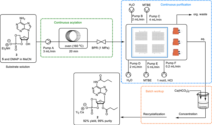
As shown in Fig. 3, the sequential continuous synthesis and purification process for dbcAMP-Ca was established. Firstly, the substrate solution was pumped into the coil reactor with a holding volume of 60 mL to achieve the full conversion from 3 to 4 at 160 ℃ in 20 min. Then the acylation output was directly pumped into the in-line purification setup containing a four-module cyclone mixer chip and three Zaiput membrane separators with the residence time of 30 s. Finally, the resulting aqueous solution was subjected to batch workup to provide the desired dbcAMP-Ca as a white solid.
In addition, we implemented a scale-up of the continuous purification process, for which the circular cyclone-type micromixer chips with wider channels were manufactured (Fig. S5 in Supporting information). The holding volume of each chip was 6.5 mL and the allowable flow rate was 0–100 mL/min. The isolated yield was maintained at 93% (purity 99%), the throughput was increased to 123 g/h, where the total flow residence time was prolonged to approximately 6 min.
In summary, we have developed a sequential continuous flow synthesis and purification process for dbcAMP-Ca. The quantitative conversion of the continuous flow acylation reaction was achieved in 20 min and the high toxic solvent pyridine was replaced by acetonitrile. In the industrial application, the continuous acylation could be further optimized by using a screw pump for solid delivery. The multistage in-line purification process based on femtosecond laser-tailored 3D circular cyclone-type micromixer chips simplified the operation and improved the process stability. The yield of dbcAMP-Ca was up to 92% (purity > 99%). Both the continuous acylation reactions and purification process could be expanded by increasing the reactor capacity. In addition, this multi-step continuous flow process overcomes the drawbacks of long reaction time, tedious operation, and unstable yields in the current synthesis process of dbcAMP-Ca and has the potential for further industrial development.
The authors declare that they have no known competing financial interests or personal relationships that could have appeared to influence the work reported in this paper.
This work was partially supported by the National Natural Science Foundation of China (No. 22278087). We acknowledge Prof. Ya Cheng and Dr. Miao Wu for their contributions to the manufacture of the glass micromixer chips using femtosecond laser micromachining, and Prof. Xuhong Qian and Prof. Weiping Zhu for their insightful guidance and discussion during the entire research.
Supplementary material associated with this article can be found, in the online version, at doi:
T. Hunter, Cell 100 (2000) 113–127. doi: 10.1016/S0092-8674(00)81688-8
W.F. Henion, E.W. Sutherland, T. Posternak, Biochim. Biophys. Acta 148 (1967) 106–113. doi: 10.1016/0304-4165(67)90284-X
M.D. Plooy, G. Michal, G. Weimann, et al., Biochim. Biophys. Acta 230 (1971) 30–39. doi: 10.1016/0304-4165(71)90051-1
T. Posternak, G. Weimann, Meth. Enzymol. 38 (1974) 399–409.
Y.D. Li, W.X. Li, Med. Recapitulate 23 (2017) 985–988.
R.W. Butcher, E.W. Sutherland, J. Bio. Chem. 237 (1962) 1244–1250. doi: 10.1016/S0021-9258(18)60316-3
J.G. Falbriard, T. Posternak, E.W. Sutherland, Biochim. Biophys. Acta 148 (1967) 99–105. doi: 10.1016/0304-4165(67)90283-8
T. Posternak, E.W. Sutherland, W.F. Henion, Biochim. Biophys. Acta 65 (1962) 558–560. doi: 10.1016/0006-3002(62)90475-4
S.Y. Choi, E.M. Chait, Patent, US2004186282, 2004.
Z. Huang, Z. Zhang, Patent, CN1554358, 2003.
J. Zhou, J. Xu, Patent, CN101020708, 2007.
W. Liu, Z. Zhang, Patent, CN105566424, 2016.
K. Alfonsi, J. Colberg, P.J. Dunn, et al., Green Chem. 10 (2008) 31–36. doi: 10.1039/B711717E
N. Atsushi, S. Susumu, Patent, JPS59155400 A, 1984.
F. Lévesque, P.H. Seeberger, Angew. Chem. Int. Ed. 51 (2012) 1706–1709. doi: 10.1002/anie.201107446
T. Tsubogo, H. Oyamada, S. Kobayashi, Nature 520 (2015) 329–332. doi: 10.1038/nature14343
A. Adamo, R.L. Beingessner, M. Behnam, et al., Science 352 (2016) 61–67. doi: 10.1126/science.aaf1337
J. Xie, D. Zhao, Chin. Chem. Lett. 31 (2020) 2395–2400. doi: 10.1016/j.cclet.2020.03.022
Y. Xin, S. Peng, J. Chen, et al., Chin. Chem. Lett. 31 (2020) 1448–1461. doi: 10.1016/j.cclet.2019.09.054
W. Li, Y. Li, W. Zhang, et al., Chin. Chem. Lett. 32 (2021) 1131–1134. doi: 10.1016/j.cclet.2020.09.039
J. Ren, M. Wu, K. Dong, et al., Chin. Chem. Lett. 34 (2023) 107694. doi: 10.1016/j.cclet.2022.07.037
A. Domokos, B. Nagy, B. Szilágyi, et al., Org. Process Res. Dev. 25 (2021) 721–739. doi: 10.1021/acs.oprd.0c00504
B. Gutmann, D. Cantillo, C.O. Kappe, Angew. Chem. Int. Ed. 54 (2015) 6688–6728. doi: 10.1002/anie.201409318
M. Movsisyan, E.I.P. Delbeke, J.K.E.T. Berton, et al., Chem. Soc. Rev. 45 (2016) 4892–4928. doi: 10.1039/C5CS00902B
J. Wegner, S. Ceylan, A. Kirschning, Adv. Synth. Catal. 354 (2012) 17–57. doi: 10.1002/adsc.201100584
R. Porta, M. Benaglia, A. Puglisi, Org. Process Res. Dev. 20 (2016) 2–25. doi: 10.1021/acs.oprd.5b00325
D.L. Hughes, Org. Process Res. Dev. 22 (2018) 13–20. doi: 10.1021/acs.oprd.7b00363
M. Sun, J. Yang, Y. Fu, et al., Org. Process Res. Dev. 25 (2021) 1160–1166. doi: 10.1021/acs.oprd.0c00543
C. Shan, L. Cao, J. Yang, et al., React. Chem. Eng. 7 (2022) 1779–1785. doi: 10.1039/d2re00145d
W. Steglich, G. Höfle, Angew. Chem. Int. Ed. 8 (1969) 981-981. doi: 10.1002/anie.196909811
G. Höfle, W. Steglich, H. Vorbrüggen, Angew. Chem. Int. Ed. 17 (1978) 569–583. doi: 10.1002/anie.197805691
N. Weeranoppanant, A. Adamo, ACS Med. Chem. Lett. 11 (2020) 9–15. doi: 10.1021/acsmedchemlett.9b00491
H. Sprecher, M.N.P. Payán, M. Weber, et al., J. Flow Chem. 2 (2012) 20–23. doi: 10.1556/jfchem.2011.00017
C. Dai, D.R. Snead, P. Zhang, J. Flow Chem. 5 (2015) 133–138. doi: 10.1556/1846.2015.00013
J.C.M. Monbaliu, T. Stelzer, E. Revalor, et al., Org. Process Res. Dev. 20 (2016) 1347–1353. doi: 10.1021/acs.oprd.6b00165
J. Ye, R. Cheng, M. Sun, et al., Patent, CN115245801, 2022.
J. Ye, R. Cheng, M. Sun, et al., Patent, CN115245800, 2022.
M. Sun, C. Liang, L. Cao, et al., Chin. Chem. Lett. 35 (2024) 108738. doi: 10.1016/j.cclet.2023.108738
S. Hou, M. Sun, L. Cao, et al., Chin. Chem. Lett. (2023) 10.1016/j. cclet. 2023.108761. doi: 10.1016/j.cclet.2023.108761
P.L. Heider A. Adamo, N. Weeranoppanant, et al., Ind. Eng. Chem. Res. 52 (2013) 10802–10808. doi: 10.1021/ie401180t

Scheme 1 Structure of cyclic adenosine-3′, 5′-monophosphate (1) and calcium dibutyryladenosine cyclophosphate (2).

Scheme 3 The acylation reaction of cAMP-Et3N in batch. General conditions: cAMP-Et3N (1 mmol, 1 equiv.), n-butyric anhydride (20 mmol, 20 equiv.), DMAP (0.01 mmol, 1 mol%), and acetonitrile (1.4 mL) were stirred at 100 ℃ for 3 h. The yield was detected by HPLC area%.

Figure 1 (a) Schematic view of the mixing mechanism of the single circular cyclone-type unit; (b) Schematic view of geometry of the four-module mixer chip; (c) Photograph of the mixer chip (contained heat transfer layers). Inset: the close view of the mixer units at the location of the red box.

Figure 2 The multistage in-line purification process. The holding volume of each module was 1.4 mL, and the allowable flow rate was 0–20 mL/min. The Zaiput membrane separators (SEP-10) ensured rapid separation of biphasic solutions using a hydrophobic membrane (OB-900). The BPRs were used to ensure the differential pressure was less than 3.5 MPa at the outlets of the separators. The yellow, blue and green lines represented the flow directions of the organic, aqueous and biphasic phases, respectively. The flow rate of each pump is: 3, 2, 4, 2, 5, 0.2 mL/min for pumps A to F, respectively.

 扫一扫看文章

扫一扫关注我们
 DownLoad:

 下载:
下载:


 下载:
下载: