Phosphorous-doped carbon nanotube/reduced graphene oxide aerogel cathode enabled by pseudocapacitance for high energy and power zinc-ion hybrid capacitors
Citation:
Junjun Yao, Fuzhi Li, Ruyi Zhou, Chenchen Guo, Xinru Liu, Yirong Zhu. Phosphorous-doped carbon nanotube/reduced graphene oxide aerogel cathode enabled by pseudocapacitance for high energy and power zinc-ion hybrid capacitors[J]. Chinese Chemical Letters,
2024, 35(2): 108354.
doi:
10.1016/j.cclet.2023.108354
Phosphorous-doped carbon nanotube/reduced graphene oxide aerogel cathode enabled by pseudocapacitance for high energy and power zinc-ion hybrid capacitors
English
Phosphorous-doped carbon nanotube/reduced graphene oxide aerogel cathode enabled by pseudocapacitance for high energy and power zinc-ion hybrid capacitors
Hunan Key Laboratory of Green Metallurgy and New Energy Materials, College of Materials and Advanced Manufacturing, Hunan University of Technology, Zhuzhou 412007, China
b.
College of packaging and Material Engineering, Hunan University of Technology, Zhuzhou 412007, China
Received Date:
15 February 2023 Accepted Date:
20 March 2023 Revised Date:
08 March 2023 Available Online:
15 February 2024
Abstract:
The design and development of energy storage device with high energy/power density has become a research hotspot. Zinc-ion hybrid capacitors (ZHCs) are considered as one of the most promising candidates. However, the application of ZHCs is hindered by their low energy density at high power density due to the unsatisfactory cathode material. In this study, a novel 3D phosphorus-doped carbon nanotube/reduced graphene oxide (P-CNT/rGO) aerogel cathode is synthesized through a synergistic modification strategy of CNT insertion and P doping modification combined with 3D porous design. The as-obtained P-CNT/rGO aerogel cathode manifests significantly increased surface aera, expanded interlayer spacing, and enhanced pseudocapacitance behavior, thus leading to significantly enhanced specific capacitance and superb ions transport performance. The as-assembled ZHC based on P-CNT/rGO cathode delivers a superior energy density of 42.2 Wh/kg at an extreme-high power density of 80 kW/kg and excellent cycle life. In-depth kinetic analyses are undertaken to prove the enhanced pseudocapacitance behavior and exceptional power output capability of ZHCs. Furthermore, the reaction mechanism of physical and chemical adsorption/desorption of electrolyte ions on the P-CNT/rGO cathode is revealed by systematic ex-situ characterizations. This work can provide a valuable reference for developing advanced graphene-based cathode for high energy/power density ZHCs.
With the proposed target of global carbon neutrality, the development and application of new energy, including solar energy, wind energy, nuclear energy and electrochemical power source, has been greatly promoted [1–3]. To achieve sustainable and stable supply of new energy, it is urgent to explore an efficient and stable energy storage system (ESS). The commercial lithium-ion batteries still face a series of problems, such as high cost, lack of lithium resources, flammable and explosive electrolytes, and toxicity [4–7]. Consequently, it is required to construct a new ESS with high specific energy/power, high safety and low manufacturing cost [8–10]. Recently, aqueous zinc-based ESS has been developed rapidly due to its high theoretical capacity, rich metal resources, cleanness and nontoxic [11–13]. Among them, zinc-ion hybrid capacitors (ZHCs) are considered as ideal candidates for next-generation ESS because they combine the merits of zinc-ion batteries with high specific energy and supercapacitors with high specific power [14–17]. However, the practical application of ZHCs is still a great challenge due to the relatively low specific energy caused by the unsatisfactory carbon-based cathode materials, resulting in the difficulty in simultaneously achieving high energy/power density.
Currently, various carbon-based cathode materials, including activated carbon [18–20], porous carbon [21,22], metal organic framework (MOF) derived carbon [23], graphene [24–26], and carbon nanotubes (CNTs) [27], were developed for high performance ZHCs. Among them, graphene is considered as a promising alternative material for energy storage because of its huge theoretical specific surface area (SSA), excellent conductivity and chemical stability [28,29]. However, the severe agglomeration issue caused by the strong van-der-Waals forces between graphene sheets greatly reduces its actual SSA and electronic conductivity, resulting in the impairment of electrochemical performance [30–32]. Thus, it is particularly important to find a simple and effective way to enhance the energy storage performance of graphene.
In order to solve the agglomeration of graphene sheets and improve the electrochemical performance of graphene, several modification methods have been carried out. Among them, 3D porous structure design can provide large SSA and short ion diffusion pathways, thereby resulting in eminent electrochemical performance. For instance, Zhao et al. and Zhang et al. prepared 3D graphene as cathode for ZHCs, demonstrating high specific capacitance, good rate performance, and excellent cycling stability [33,34]. Moreover, compared with pure graphene, the construction of graphene-based composite materials can not only effectively prevent the agglomeration of graphene sheets, but also promote the synergistic improvement of electrochemical properties. Among them, the combination of graphene and pseudocapacitance materials, such as polyaniline (PANI) [35], polypyrrole (PPy) [36,37] and niobium oxyphosphide (NbPO) [38], is an effective method to improve the specific capacitance of graphene-based materials. In addition, the functionalization of graphene surface can improve the electrolyte wettability and surface reactivity of electrode, thus promoting the chemical adsorption/desorption of Zn2+. Shao et al. synthesized functionalized graphene with optimized oxygen-containing functional groups and applied it to ZHC, which facilitates the pseudocapacitance reaction between Zn2+ and graphene, thereby effectively improving the energy density of ZHC [24]. Nevertheless, the above researches usually show poor specific energy at high specific power, which limits their application in rapid charging/discharging scenarios. Based on the above discussion, the electrochemical performance of graphene can be significantly improved by combining various modification methods. Thus, it is highly expected that the as-developed 3D graphene optimized by co-modification of intercalators and heteroatom doping will achieve high energy output at high power density. Meanwhile, the storage mechanism of electrolyte ions in graphene-based electrode materials modified by heteroatom doping, especially P doping in ZHCs, is not clear, which still needs to be further clarified.
Herein, we developed a novel 3D P-CNT/rGO composite aerogel through a simple one-step hydrothermal method utilizing CNTs as intercalators and phytic acid as phosphorus source, respectively, and further used as the cathode for ZHC for the first time. The optimized P-CNT/rGO composite aerogel displays enhanced SSA, enlarged interlayer spacing, and improved pseudocapacitance behavior due to CNT insertion and P doping modification combined with 3D porous design, which leads to significantly increased specific capacitance and good rate performance. Specifically, the P-CNT/rGO electrode achieves a much higher specific capacitance (213.4 F/g at 0.5 A/g) than that of rGO (105.9 F/g) and CNT/rGO (144.1 F/g). Notably, the as-constructed P-CNT/rGO-based ZHC demonstrates a superb power density (80 kW/kg at 42.2 Wh/kg) and a satisfactory energy density (92.7 Wh/kg at 80 W/kg). Besides, the as-assembled P-CNT/rGO-based ZHC exhibits splendid cycle stability (94.2% capacitance retention after 10,000 cycles at 3 A/g). Simultaneously, the systematically capacitive contribution and electrochemical reaction kinetic analyses were employed to prove the enhanced pseudocapacitance behavior and remarkable power performance of the P-CNT/rGO-based ZHC. More importantly, the reaction mechanism of physical and chemical adsorption/desorption of electrolyte ions on the P-CNT/rGO cathode was detected by ex-situ X-ray diffraction (XRD), field emission scanning electron microscopy (FESEM) and X-ray photoelectron spectroscopy (XPS). This work not only provides a reasonable method for the preparation of advanced graphene-based cathode materials with high energy density ZHCs at high power density, but also for the first time elucidates the energy storage mechanism of P-doped graphene-based materials in ZHCs and the influence of P doping on the electrochemical performance of graphene-based materials.
The P-CNT/rGO composite aerogel was prepared via one-step hydrothermal method (Fig. 1a). During the preparation process, CNTs are dispersed between graphene sheets and act as intercalators to prevent the agglomeration of graphene, thus improving the actual SSA and electronic conductivity of graphene. Due to the larger atomic diameters and lower electronegativity than C atoms, the introduction of P atoms can provide more structural defects in the composite aerogel and change the charge density of graphene, thus significantly improving the capacitive properties of graphene [39]. In the digital images of rGO, CNT/rGO and P-CNT/rGO aerogels, the changes of volume can be visually observed (Fig. S1 in Supporting information). Compared with rGO and CNT/rGO, the P-CNT/rGO shows the largest size of the cylinder on account of CNT insertion and P doping modification, which indicates the effectively increased SSA and interlayer distance of the composite aerogel, contributing to the enhancement of electrochemical performance. The FESEM, TEM and elemental mapping were undertaken to investigate the morphology and microstructure of rGO, CNT/rGO and P-CNT/rGO. It can be observed from the FESEM images (Figs. 1b-g) that the P-CNT/rGO possesses more abundant wrinkles and porous network structure compared with rGO and CNT/rGO, which is beneficial for the improvement of the capacitive properties of P-CNT/rGO. Based on the TEM images (Figs. 1h and i), it is clearly seen that the CNTs are uniformly distributed among the graphene sheets, and the P-CNT/rGO presents a porous network nanostructure. Meanwhile, the HRTEM image confirms the enlarged interlayer spacing of P-CNT/rGO (Fig. S2 in Supporting information), which is larger than that of graphene as reported in the literature [40,41]. Moreover, as displayed in the elemental mapping of P-CNT/rGO (Fig. 1j), the C, O and P elements are homogeneously dispersed in the composite aerogel, indicating that the P atoms are successfully doped into the P-CNT/rGO composite aerogel.
Figure 1
Figure 1.
(a) Schematic illustration displaying the synthesis of P-CNT/rGO composite aerogel. FESEM images of (b, c) rGO, (d, e) CNT/rGO and (f, g) P-CNT/rGO. (h, i) TEM images and (j) elemental mappings of C, O and P elements of P-CNT/rGO.
The XRD and Raman test were employed to further study the structural features of rGO, CNT/rGO and P-CNT/rGO. In the XRD pattern (Fig. 2a), the diffraction peaks at 2θ = 24.6° and 43.1° are assigned to the (002) and (100) crystalline planes, respectively [42,43]. According to the Bragg's law, the interlayer spacing of rGO, CNT/rGO and P-CNT/rGO is calculated to be 0.353, 0.358 and 0.363 nm, respectively. The significantly enlarged interlayer spacing of P-CNT/rGO proves that the synergistic effect of CNT insertion and P doping modification has a positive role in reducing the agglomeration of graphene. In Raman spectra, the intensity ratio of D band to G band (ID/IG) reflects the disordered degree of carbon-based materials [21,44]. As demonstrated in Fig. 2b, the ID/IG ratio of rGO, CNT/rGO and P-CNT/rGO is, respectively 1.00, 1.02 and 1.07, verifying the enhanced defects and disorder degree of P-CNT/rGO, which is beneficial to the enhancement of electrochemical properties.
Figure 2
Figure 2.
(a) XRD patterns and (b) Raman spectra of rGO, CNT/rGO and P-CNT/rGO. High resolution XPS spectra of (c) C 1s, (d) O 1s, and (e) P 2p of P-CNT/rGO. (f) Nitrogen adsorption-desorption test of rGO, CNT/rGO and P-CNT/rGO.
The surface chemical compositions of P-CNT/rGO were detected by XPS. As shown in Fig. 2c, the C 1s XPS spectrum can be divided into four peaks at 284.8, 285.9, 286.7 and 288.5 eV, indexing to the C-C, C-P, C-O and C=O [25,45], respectively. In the O 1s XPS spectrum (Fig. 2d), three peaks located at 531.3, 532.6 and 533.5 eV can be attributed to the O-C=O, C-O/P-O and C=O [46,47], respectively. For the P 2p spectrum (Fig. 2e), the peaks situated at 133.6 and 134.7 eV are assigned to the P-C and P-O [48,49], respectively, and the content of P atom in P-CNT/rGO is ~1.14% (Table S1 in Supporting information). Accordingly, the appearance of above bonds further confirms that the P atoms are successfully doped into the composite aerogel. It is worth emphasizing that both oxygen-containing functional group and the introduction of P atoms can contribute to additional pseudocapacitance, thus improving the specific capacitance of the P-CNT/rGO composite aerogel [42,50]. Moreover, nitrogen adsorption/desorption test was implemented to study the SSA and pore size distribution of rGO, CNT/rGO and P-CNT/rGO. The N2 adsorption/desorption isotherms of rGO, CNT/rGO and P-CNT/rGO display a combined Ⅰ/Ⅳ isotherms, indicating the co-existence of micropores and mesopores structure, as exhibited in Fig. 2f. The pore size distribution curves show that the P-CNT/rGO has the most abundant micropores and mesopores resulting from the synergistic effect of CNT insertion and P doping modification. The micropores and mesopores are mainly situated at the size range of 0.7–1.8 nm and 2.3–3.8 nm, respectively. Furthermore, the P-CNT/rGO (236.7 m2/g, 0.41 cm3/g) exhibits a higher BET SSA and total pore volume compared with rGO (113.8 m2/g, 0.27 cm3/g) and CNT/rGO (195.8 m2/g, 0.36 cm3/g), which is beneficial for the ions storage and fast transport during the electrochemical reaction process.
The above characterization analyses suggest that CNT insertion and P doping modification combined with the 3D porous design can effectively reduce the agglomeration of graphene sheets, provide reasonable porous structure, enlarge the interlayer spacing and improve the SSA of graphene, which is beneficial for the enhancement of electrochemical properties of graphene. Thus, it is highly anticipated that the P-CNT/rGO cathode will present excellent energy storage performance in ZHCs. To evaluate the differences of electrochemical properties of rGO, CNT/rGO and P-CNT/rGO, a coin-type ZHC was constructed by using Zn foil as anode/current collector, 2 mol/L ZnSO4 as electrolyte, and rGO, CNT/rGO or P-CNT/rGO as cathode, respectively. Schematic in Fig. 3a shows the construction of P-CNT/rGO-based ZHC. As displayed in Fig. 3b, the CV curve of the P-CNT/rGO electrode shows the largest peak current and enclosed area than those of the rGO and CNT/rGO electrodes, suggesting the highest specific capacitance of the P-CNT/rGO electrode. In addition, the P-CNT/rGO electrode manifests more obvious redox peaks than the rGO and CNT/rGO electrodes, disclosing the enhanced pseudocapacitance due to the P doping. Fig. 3c manifests the GCD curves of the rGO, CNT/rGO and P-CNT/rGO electrodes at 0.5 A/g. The calculated specific capacitance of the rGO, CNT/rGO and P-CNT/rGO electrodes is 105.9, 144.1 and 213.4 F/g, respectively. Compared with the rGO electrode, the CNT/rGO electrode shows increased specific capacitance, which originates from the improved SSA and enlarged interlayer spacing caused by the intercalation of CNTs. Moreover, the P-CNT/rGO electrode exhibits a further improvement in specific capacitance compared with the CNT/rGO electrode due to the additional pseudocapacitance caused by P doping, further proving that the synergistic effect of CNT insertion and P doping modification can distinctly enhance the electrochemical performance of graphene. Fig. S3 (Supporting information) shows the GCD curves of the rGO, CNT/rGO and P-CNT/rGO electrodes at different current densities, and the as-obtained specific capacitances are illustrated in Fig. 3d. Note that the P-CNT/rGO electrode can still achieve a superior specific capacitance of 118.8 F/g even at an ultrahigh current density of 100 A/g, which is much higher than that of the rGO and CNT/rGO electrodes. Besides, the P-CNT/rGO-based ZHC also displays a remarkable cycling stability with 94.2% capacitance retention even after 10,000 cycles and about 100% Coulombic efficiency (Fig. 3e). More importantly, the P-CNT/rGO-based ZHC still delivers an encouragingly energy density of 42.2 Wh/kg (based on the mass of P-CNT/rGO cathode) even at an ultrahigh power density of 80 kW/kg, outperforming most of previously reported ZHCs, including NPG//Zn (48.3 Wh/kg at 4.5 kW/kg) [34], rGO-NbPO//Zn (56.03 Wh/kg at 1.0 kW/kg) [38], PC//Zn (40.4 Wh/kg at 48.8 kW/kg) [43], BGC//Zn (45 Wh/kg at 61.7 kW/kg) [44], AC//Zn (30 Wh/kg at 14.9 kW/kg) [51], N-OPCNF//Zn (42 Wh/kg at 33.2 kW/kg) [52], TiN//Zn (56 Wh/kg at 3.5 kW/kg) [53], CT/SWNT//Zn (54 Wh/kg at 15.1 kW/kg) [54], and WC-6ZnN-12 U//Zn@CC (43.3 Wh/kg at 6.8 kW/kg) [55]. A maximum energy density of 92.7 Wh/kg at a power density of 80 W/kg can be achieved at 0.1 A/g, demonstrating the high energy delivery (Fig. 3f). As exhibited in Figs. 3g and h, two kinds of LED board (1.5 and 3 V) were successfully lightened by connecting the P-CNT/rGO-based ZHCs in series, manifesting the huge potentials of the as-assembled ZHCs for commercial applications.
Figure 3
Figure 3.
Electrochemical performance of as-assembled ZHCs: (a) Configuration of the P-CNT/rGO-based ZHC. (b) CV curves at 20 mV/s. (c) GCD curves at 0.5 A/g. (d) Specific capacitance at diverse current densities. (e) Cycling performance of the P-CNT/rGO-based ZHC at 3 A/g. (f) Ragone plot of the P-CNT/rGO-based ZHC. (g, h) Photographs of a LED board powered by ZHCs in series.
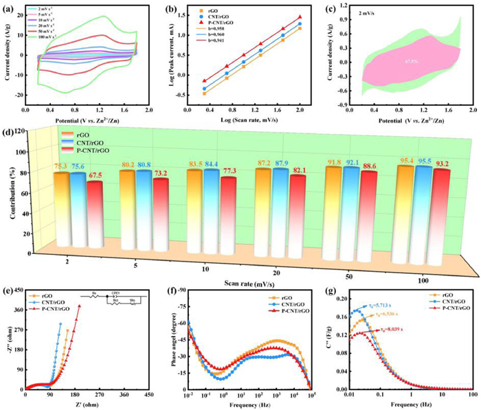
The electrochemical kinetic behaviors of the rGO, CNT/rGO and P-CNT/rGO electrodes were further studied. As exhibited in Fig. 4a and Fig. S4 (Supporting information), the CV curves of the rGO, CNT/rGO and P-CNT/rGO electrodes do not undergo obvious deformation with the increase of scan rates from 2 mV/s to 100 mV/s, demonstrating the superior electrochemical reaction kinetics. Moreover, the CV curves of all electrodes are approximately rectangular with distinct redox peaks, implying the co-existence of the electrochemical double layer capacitance (EDLC) and pseudocapacitance behaviors during the charge/discharge process. The b-value reflects the logarithms relationship between peak current (i) and scan rate (v), which can be calculated according to the formula: i = av. Generally, the b-value of 1 stands for a typical supercapacitive behavior with rapid reaction kinetics, while the b-value of 0.5 represents a diffusion-controlled reaction process [56–58]. In Fig. 4b, the obtained b-value of the rGO, CNT/rGO and P-CNT/rGO electrodes is 0.958, 0.960 and 0.941, respectively. Obviously, the P-CNT/rGO electrode has a stronger diffusion-controlled behavior than that of the rGO and CNT/rGO electrodes, which is attributed to the enhanced pseudocapacitance caused by P doping, leading to the significantly increased capacitance. The contribution ratio of capacitive/diffusion-controlled response current (i) is calculated by the following equation: i = k1v + k2v1/2, where k1v and k2v1/2, respectively represent the capacitive and diffusion-controlled process [59–61]. The capacitive contribution ratio of the rGO and CNT/rGO electrodes is displayed in Figs. S5 and S6 (Supporting information), respectively. It is worth noting that the P doping can provide more active sites on the surface of cathode for the chemical adsorption/desorption of Zn2+, which results in increased pseudocapacitance contribution and thus achieve high capacitance of the P-CNT/rGO electrode, (Fig. 4c and Fig. S7 in Supporting information). Additionally, when the scan rate rises from 2 mV/s to 100 mV/s, the capacitive contribution ratio for the rGO, CNT/rGO and P-CNT/rGO electrodes increases from 75.3% to 95.4%, 75.6% to 95.5% and 67.5% to 93.2%, respectively (Fig. 4d). Thus, it is obvious that the P-CNT/rGO electrode possesses a capacitive dominant process at high scan rate, manifesting the fast reaction kinetics, which well illustrates the splendid power performance of the P-CNT/rGO-based ZHC.
Figure 4
Figure 4.
(a) CV curves of the P-CNT/rGO-based ZHC at different scan rates. (b) log(i) vs. log(v) plots of rGO, CNT/rGO and P-CNT/rGO at specific peak current. (c) Capacitive contribution of P-CNT/rGO at 2 mV/s. (d) Capacitive contribution ratio at diverse scan rates, (e) Nyquist plots, (f) Bode plot, and (g) the imaginary capacitance C”(ω) of rGO, CNT/rGO and P-CNT/rGO.
The EIS measurement was undertaken to study the changes of charge transfer kinetics of the rGO, CNT/rGO and P-CNT/rGO electrodes. As described in Fig. 4e, the charge transfer resistance (Rct) of the rGO, CNT/rGO and P-CNT/rGO electrodes is 86.7, 79.6 and 95.1 Ω, while the internal resistance (Rs) is 1.02, 0.94 and 1.06 Ω, respectively, which is in agreement with the CV and GCD results. Besides, the phase angle of the rGO, CNT/rGO and P-CNT/rGO electrodes is 56.9°, 61.2° and 52.6°, respectively, as exhibited in Bode plots (Fig. 4f). Usually, the phase angle of 90° suggests an ideal capacitive behavior, and the above results further prove the order of capacitive/diffusion-controlled contribution [61]. Moreover, the relaxation time constant (τ0) is calculated as 6.536, 5.713 and 8.039 s for the rGO, CNT/rGO, and P-CNT/rGO electrodes (Fig. 4g), respectively. The increased τ0-value of the P-CNT/rGO electrode can be ascribed to the enhanced pseudocapacitance behavior, which is favorable for the improvement of capacitance [21]. More importantly, the τ0-value of the P-CNT/rGO electrode is much lower than the previously reported graphene-based electrode material (29 s) [24], which discloses the rapid ion diffusion inside the P-CNT/rGO electrode, further confirming the outstanding power performance of the P-CNT/rGO-based ZHC.
In order to explore the energy storage mechanism of the P-CNT/rGO-based ZHC, in-depth ex-situ characterizations were employed to reveal the compositional variations in electrodes during the discharging/charging process. Fig. 5a illustrates the GCD curve of the P-CNT/rGO-based ZHC. Five typical states (marked as A to E) are chosen to study the transformation of chemical compositions of anode/cathode. The ex-situ XRD patterns of Zn anode display puny variation except for the appearance of weak diffraction peaks (Figs. 5b and c), which originates from the formation of Zn4SO4(OH)6·5H2O (PDF#39–0688) on the surface of Zn foil. Meanwhile, the appearance of lamellar Zn4SO4(OH)6·5H2O can be detected from the FESEM images of Zn anode, as manifested in Fig. S8. For the P-CNT/rGO cathode, the Zn4SO4(OH)6·5H2O can also be observed during the discharging/charging process (Figs. 5d and e). When discharging to state C (0.2 V), the peak intensity reaches the highest and gradually disappears with the charging process, indicating a reversible precipitation/dissolution reaction of Zn4SO4(OH)6·5H2O [62]. Furthermore, it is noted that the diffraction peaks of the P-CNT/rGO cathode maintain unchanged at diverse states, which implies that the ion adsorption/desorption on the surface of P-CNT/rGO is the main route for energy storage. The changes of morphology and microstructure of the P-CNT/rGO cathode were further characterized by ex-situ FESEM test (Figs. S9a-e in Supporting information). It is clearly seen that the Zn4SO4(OH)6·5H2O sheets show a reversible increase and disappearance process, and the corresponding elemental mappings of Zn, S and O are exhibited in Fig. S9f (Supporting information). The above results imply that the formation of Zn4SO4(OH)6·5H2O has a negligible contribution to the capacitance of the P-CNT/rGO-based ZHC [51]. Moreover, it has been reported that the existence of Zn4SO4(OH)6·5H2O has a series of influence on the electrochemical performance of the P-CNT/rGO-based ZHC [63]. The generation of Zn4SO4(OH)6·5H2O can broaden the voltage window, thereby improving the energy density of the P-CNT/rGO-based ZHC. However, the Zn4SO4(OH)6·5H2O covering on the surface of P-CNT/rGO leads to the increase of Rct during the electrochemical reactions, which is harmful to the rate performance and cycling stability of the P-CNT/rGO-based ZHC [63]. The corresponding EIS plots at diverse states are displayed in Fig. S10 (Supporting information), and the order of Rct accords well with the regularity of the formation of Zn4SO4(OH)6·5H2O, verifying the impact of Zn4SO4(OH)6·5H2O on the electrochemical properties of the P-CNT/rGO-based ZHC.
Figure 5
Figure 5.
(a) GCD profile of the P-CNT/rGO-based ZHC at 1 A/g. Ex-situ XRD spectra of (b, c) the Zn anode, and (d, e) P-CNT/rGO cathode. (f) The XPS spectra of Zn 2p at pristine, fully charging and discharging states and ex-situ high-resolution (g) C 1s, (h) O 1s and (i) P 2p XPS spectra at different states of the P-CNT/rGO cathode. (j) Schematic illustration of energy storage mechanism of the P-CNT/rGO based ZHC.
To explore the Zn2+ storage mechanism on the P-CNT/rGO cathode in more detail, ex-situ XPS test was conducted to study the change of chemical compositions at different states. As shown in the Zn 2p spectra (Fig. 5f), the Zn2+ is reserved in the P-CNT/rGO cathode when the P-CNT/rGO-based ZHC is discharged from pristine state to state C (0.2 V), and nearly all Zn2+ is detached from the P-CNT/rGO cathode when the ZHC is recharged to state E (1.8 V), demonstrating a highly reversible reaction process between Zn2+ and P-CNT/rGO cathode [64]. As exhibited in the high-resolution C 1s spectra (Fig. 5g), the two typical peaks located at 287.7 and 290.8 eV are related to the C-O-Zn and O=C-O-Zn, respectively, proving the existence of chemical adsorption/desorption reactions of Zn2+ with oxygen-containing functional group [21,24]. Furthermore, the area ratio of C-O-H/C-O-Zn is reduced from state A (1.8 V) to state C (0.2 V) and then increases to state E (1.8 V), indicating the highly reversible chemical adsorption/desorption reactions between Zn2+ and oxygen-functional groups, which can provide additional pseudocapacitance contribution. As shown in the high-resolution O 1s spectra (Fig. 5h), the typical peak at 530.9 eV corresponds to the O-Zn, whose area reaches the maximum when discharging to state C, and disappears in the subsequent charging process, which is attributed to the chemical adsorption/desorption reaction between Zn2+ and C-O or P-O [50]. The P-O exhibits a similar reaction process as the C-O, which can be detected in the high-resolution P 2p spectra. As displayed in Fig. 5i, the binding energy of P-O peak gradually rises from state A to state C and then declines in the subsequent charging process, indicating the reversible chemical adsorption/desorption reaction between Zn2+ and P-O [48,65], which further proves the enhanced pseudocapacitance behavior due to the P doping modification. It is worth emphasizing that the highly reversible pseudocapacitance reactions between Zn2+ and P-CNT/rGO cathode facilitate the high energy output of the P-CNT/rGO-based ZHC at high power density. According to the above discussion, the energy storage reactions of the P-CNT/rGO-based ZHC can be summarized as follows (Fig. 5j):
Anode:
(1)
Cathode:
(1) Physical adsorption/desorption (EDLC)
(2)
(2) Chemical adsorption/desorption (Pseudocapacitance)
(3)
(4)
Side reaction:
(5)
In summary, the novel 3D P-CNT/rGO composite aerogel is synthesized via a simple one-step hydrothermal method. When served as cathode materials for ZHC, the as-prepared P-CNT/rGO composite aerogel displays significantly increased specific capacitance (213.4 F/g at 0.5 A/g) compared with rGO (105.9 F/g) and CNT/rGO (144.1 F/g). Moreover, the as-obtained P-CNT/rGO composite aerogel achieves a good rate performance with 45.5% capacitance retention at an ultrahigh current density of 100 A/g compared with 0.1 A/g. The good electrochemical performance of P-CNT/rGO can be attributed to the improved SSA, enlarged interlayer spacing, and enhanced pseudocapacitance reactions, which originates from the synergism of CNT insertion and P doping modification combined with 3D porous design. Further, the as-assembled P-CNT/rGO-based ZHC exhibits a high energy density of 92.7 Wh/kg at a power density of 80 W/kg, an exceptional power density of 80 kW/kg at a gratifying energy density of 42.2 Wh/kg, as well as a superb service life over 10,000 cycles at 3 A/g with a capacitance retention of 94.2%. The distinguished power performance of the P-CNT/rGO-based ZHC is investigated through systematic electrochemical kinetic analyses (including CV and EIS tests). Simultaneously, the in-depth ex-situ characterizations, including XRD, FESEM, XPS, and EIS were conducted to survey the reaction mechanism of physical and chemical adsorption/desorption of electrolyte ions on the P-CNT/rGO cathode in detail. It is believed that this work not only offers a good reference and guidance to design and prepare high-performance graphene-based cathode materials for high energy/power density ZHCs, but also reveals the influence of P doping on the electrochemical performance and the reaction mechanism of physical and chemical adsorption/desorption of electrolyte ions in P-doped carbon-based materials.
Declaration of competing interest
The authors declare that they have no known competing financial interests or personal relationships that could have appeared to influence the work reported in this paper.
Acknowledgments
The work is financially supported by Distinguished Young Scientists of Hunan Province (No. 2022JJ10024), National Natural Science Foundation of China (No. 21601057), Natural Science Foundation of Hunan Province (No. 2021JJ30216), and Key Projects of Hunan Provincial Education Department (No. 22A0412).
X.Y. Deng, J.J. Li, Z. Shan, et al., J. Mater. Chem. A 8 (2020) 11617–11625. doi: 10.1039/d0ta02770g
Figure 1
(a) Schematic illustration displaying the synthesis of P-CNT/rGO composite aerogel. FESEM images of (b, c) rGO, (d, e) CNT/rGO and (f, g) P-CNT/rGO. (h, i) TEM images and (j) elemental mappings of C, O and P elements of P-CNT/rGO.
Figure 2
(a) XRD patterns and (b) Raman spectra of rGO, CNT/rGO and P-CNT/rGO. High resolution XPS spectra of (c) C 1s, (d) O 1s, and (e) P 2p of P-CNT/rGO. (f) Nitrogen adsorption-desorption test of rGO, CNT/rGO and P-CNT/rGO.
Figure 3
Electrochemical performance of as-assembled ZHCs: (a) Configuration of the P-CNT/rGO-based ZHC. (b) CV curves at 20 mV/s. (c) GCD curves at 0.5 A/g. (d) Specific capacitance at diverse current densities. (e) Cycling performance of the P-CNT/rGO-based ZHC at 3 A/g. (f) Ragone plot of the P-CNT/rGO-based ZHC. (g, h) Photographs of a LED board powered by ZHCs in series.
Figure 4
(a) CV curves of the P-CNT/rGO-based ZHC at different scan rates. (b) log(i) vs. log(v) plots of rGO, CNT/rGO and P-CNT/rGO at specific peak current. (c) Capacitive contribution of P-CNT/rGO at 2 mV/s. (d) Capacitive contribution ratio at diverse scan rates, (e) Nyquist plots, (f) Bode plot, and (g) the imaginary capacitance C”(ω) of rGO, CNT/rGO and P-CNT/rGO.
Figure 5
(a) GCD profile of the P-CNT/rGO-based ZHC at 1 A/g. Ex-situ XRD spectra of (b, c) the Zn anode, and (d, e) P-CNT/rGO cathode. (f) The XPS spectra of Zn 2p at pristine, fully charging and discharging states and ex-situ high-resolution (g) C 1s, (h) O 1s and (i) P 2p XPS spectra at different states of the P-CNT/rGO cathode. (j) Schematic illustration of energy storage mechanism of the P-CNT/rGO based ZHC.


 DownLoad:


 下载:
下载:


 下载:
下载:
