Received Date:
29 September 2022 Accepted Date:
24 October 2022 Revised Date:
11 October 2022 Available Online:
15 August 2023
Abstract:
For several decades, the promise of implementing of lithium (Li) metal anodes for Li batteries has been a "holy grail" for researchers. Herein, we have proposed a facile design of a MOF-derived Co3O4 nanoparticles modified nickel foam, i.e., Co3O4-NF, as a 3D host to achieve a uniform infusion of the molten Li. The molten Li was uniformly absorbed on the Co3O4-NF host only in 10 s due to its high Li lithiophilicity. The obtained Li-Co3O4-NF composite electrode shows high cycling stability in symmetric cells with low voltage hysteresis even at a high current density of 5 mA/cm2. The full cells of Li-Co3O4-NF/LiFePO4 can cycle for more than 500 cycles at 2C without obvious capacity decay. SEM after cycling and in situ optical microscope results suggest that the unique 3D host structure of the Li-Co3O4-NF anode plays key roles on suppressing the dendrite growth and decreasing the local current inhomogeneity. We believe this work might provide a new strategy for fabricating dendrite-free Li metal anodes and facilitate practical applications in Li batteries.
With the rapid development of portable electronic products and electric vehicles (EVs), high requirements have been put forward on the secondary batteries with high energy density. Currently, the conventional graphite anodes for lithium (Li) ion batteries are limited by their relatively low theoretical capacity (372 mAh/g) [1–4]. Li metal is considered as the next generation anode due to its high theoretical capacity (3,860 mAh/g) and lowest anode potential (−3.04 V vs. H+/H2) [5–8]. However, the high activity of metallic Li led to serious side reactions with organic liquid electrolyte, resulting in irreversible consumption of metallic Li and large accumulation of inactive Li [9–11]. In addition, the volume deformation and Li dendrite formation during the discharge-charge processes will deteriorate its cycling stability and result in internal short circuit and even explosion [12–17], which seriously limit the practical application of Li metal anode.
At present, a series of strategies were applied to alleviate the chemical reaction between the Li anode and organic electrolyte, and suppress the Li dendrite formation, such as artificial solid electrolyte interphase (SEI) layer [18–20], electrolyte additives [21–23], solid electrolyte [24–26], three-dimensional (3D) host anodes [27–29]. Among them, the design of 3D structured anode is one of the most promising strategies to solve the shortcomings of Li metal anode. The 3D conductive framework has a high specific surface area, which can significantly reduce the local current density of the anode, so as to delay the initial nucleation time of Li dendrite [30,31]. Moreover, the 3D framework can efficiently confine the uncontrolled Li deposition and alleviate the volume expansion of Li metal during the discharge-charge processes [32,33]. However, the commonly used 3D skeletons (nickel foam (NF) [34,35], copper foam [36,37], carbon cloth [38–40], etc.) are lithiophobic, thus lithiophilic materials (transition metal oxides (TMOs)), such as CuO [41,42], MnO2 [43,44], CoO [45,46]and Al2O3 [47], should be deposited on the surface of the 3D skeletons by electrochemical deposition [48,49], atomic deposition [50,51] or thermal spraying [52] to improve the Li affinity. For instance, Chen et al. [53] deposited an ultrathin ZnO layer on 3D Cu pillars by atomic layer deposition (ALD) to improve the wettability between metallic Li and 3D hosts and prepared composite Li metal anode. The ZnO layer effectively promotes uniform Li nucleation. However, the above techniques need high preparation cost and complex operations, which are not suitable for large scale applications or commercialization.
As an emerging class of crystalline porous materials, metal–organic frameworks (MOFs) which constructed by metal ions or clusters and organic ligands, have received great attentions due to their wide applications [54–56]. Recently, MOFs have been widely used as the precursors for synthesizing nano TMOs, such as CuO [41,42], MnO2 [43,44], CoO [45,46] and Al2O3 [47]. Due to the large surface area, high porosity and tunable metal nodes, the MOFs-derived TMOs should have good wettability with Li metal. In recent years, some studies are devoted to the combination of 3D skeletons and MOFs-derived TMOs to construct 3D Li anodes [57–59]. Even so, how to simplify the preparation of 3D Li anodes remains to be further explored.
In this work, we proposed a facile design of a MOF-derived Co3O4 nanoparticles modified NF, i.e., Co3O4-NF, as a 3D host for uniform infusion of the molten Li to obtain the Li-Co3O4-NF composite anode (Scheme 1). The 3D NF networks have been widely used owing to their excellent structural integrity and electrical conductivity. The composite anode can effectively suppress Li dendrite growth by decreasing the local current density and restricting the volume change of Li within the porous structure of the 3D NF networks, which enables the hierarchical host to accommodate high areal loading of Li. Batteries assembled with commercial LiFePO4 (LFP) cathode, and the Li-Co3O4-NF composite anode exhibit outstanding cycling stability and rate capability.
Scheme 1
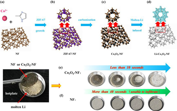
Scheme 1.
Synthesis and molten Li infusion procedure of the Co3O4-NF electrode. (a) Pure NF, (b) ZIF-67-NF, (c) Co3O4-NF, (d) Li-Co3O4-NF. Photographs of the infusion processes of molten Li into the NF hosts (e) pure NF and (f) Co3O4-NF (within 10 s).
The preparation of Li-Co3O4-NF composite anode was shown in Scheme 1. Briefly, ZIF-67 nanoparticles modified NF (ZIF-67-NF, Schemes 1a and b) was firstly prepared with pure NF in the solution of cobalt nitrate and 2-methylimidazole via a facile room-temperature reaction. The Co3O4 modified NF (Co3O4-NF) was prepared via the carbonization of ZIF-67-NF (Scheme 1c). Final Li-Co3O4-NF composite anode was obtained after the infusion of molten Li into Co3O4-NF (Scheme 1d). The detailed infusion processes are shown in Scheme 1e and Supporting information. When the Co3O4-NF was put on the top of molten Li, the molten Li was uniformly and fast infused into the whole Co3O4-NF skeleton. The whole process of Li infusion is completed in 10 s, which is much shorter than relevant studies [60]. It indicates the good Li affinity of Co3O4-NF skeleton. For comparison, the molten Li cannot infiltrate into pure NF even after 40 s at the same temperature (Scheme 1f).
X-ray diffraction (XRD), transmission electron microscopy (TEM), and high-resolution transmission electron microscopy (HRTEM) were tested to investigate the crystal structure and microstructure of ZIF-67 precursor and Co3O4 scrapped from Co3O4-NF. The XRD curves of the prepared MOFs (ZIF-67) and Co3O4 particles are shown in Fig. S1 (Supporting information). All the diffraction peaks of the samples are matched with simulated peaks of ZIF-67 and cubic Co3O4 (PDF#43-1003) well. The diffraction peaks at 19°, 31.2°, 36.8° and 44.8° are assigned to the (111), (220), (331) and (400) planes of cubic Co3O4, respectively. Fig. 1a shows a low-magnification TEM image of Co3O4 nanoparticles, which demonstrates that the carbon skeleton and nanoparticles are formed after the carbonization of ZIF-67. Fig. 1b presents the SAED patterns of Co3O4 particles. The observed (511) and (311) planes of Co3O4 proves the presence of ZIF-67-derived Co3O4 particles. As shown in the HRTEM image (Figs. 1c and d), the lattice fringes about 0.47 nm, 0.243 nm, 0.294 nm correspond to the (111), (311), (220) planes of Co3O4, respectively. The XRD and HRTEM results suggest that the Co3O4 powder is successfully obtained by one-step calcination of ZIF-67.
Figure 1
Figure 1.
Characterizations of the Co3O4-NF electrode. (a) TEM image, (b) SAED patterns, (c, d) HRTEM image of Co3O4 particles. The Co3O4 particles were scraped off from Co3O4-NF electrode disks.
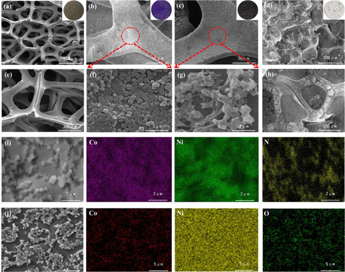
Fig. 2 shows the SEM images of the as-prepared NF, ZIF-67-NF, Co3O4-NF, Li-Co3O4-NF. The cleaned NF has a perfect 3D structure with smooth surface and pore size of 300-500 µm (Figs. 2a and e). Uniform and legible dodecahedral ZIF-67 particles with a diameter of ~ 250 nm are in situ formed and embedded in the NF skeletons tightly and the color changes to purple (Fig. 2b, Figs. S2a, b and f in Supporting information). After carbonization, the ZIF-67 particles are replaced by Co3O4 and the 3D network structure is well maintained after the heating treatment, the sizes of Co3O4 particles are about 100-200 nm (Figs. 2c and g). The color of the electrode changed from purple to black after Co3O4 decoration (inset of Figs. 2b and c). Figs. 2d and h, Figs. S2c and d (Supporting information) show the SEM images of Li-Co3O4-NF. The surface of the Li-Co3O4-NF composite anode is smooth, and Li is fully immersed into the 3D NF skeletons. It indicates that Co3O4 particles derived from ZIF-67 efficiently improves the wettability of NF and Li metal. The uniform distribution of Co and N element on the surface of Co3O4-NF is shown in the EDS mapping images (Fig. 2i), which suggests the uniform growth of ZIF-67 particles without aggregation during the reaction. Fig. 2j shows the uniform distribution of Co and O element of Co3O4 on the surface of NF.
Figure 2
Figure 2.
SEM images of (a) NF, (b) ZIF-67-NF, (c) Co3O4-NF, (d) Li-Co3O4-NF (inset are the photos). Magnified SEM images of (e) NF, (f) ZIF-67-NF, (g) Co3O4-NF, (h) Li-Co3O4-NF. (i) EDS mappings of ZIF-67-NF. (j) EDS mappings of Co3O4-NF.
Coulombic efficiency (CE), defined as the ratio of discharge capacity to charge capacity in each charging/discharging cycle, is regarded as an essential parameter to evaluate the practicality and sustainability of the working electrode in Li metal batteries [60]. Here, the Li/NF and the Li/Co3O4-NF half cells were assembled to illustrate the effect of the ZIF-67-derived Co3O4 nano-particles on the uniform Li deposition. The nucleation barrier, which is defined as the potential gap between the inflection point of the discharge curve and the zero potential, corresponds the difficulty of the Li nucleation on the electrode surface [61]. Smaller nucleation barrier and lower voltage hysteresis of the Co3O4-NF electrode than that of the NF electrode indicate that the Li nucleation and plating process on the Co3O4-NF electrode was easier than that on the NF electrode (Fig. S3a in Supporting information). As shown in Fig. S3b (Supporting information), the Co3O4-NF electrode delivered high and stable CEs (nearly 100%) during the long-term charging/discharging processes at the current density of 1 mA/cm2 with the areal capacity of 1 mAh/cm2. The Li/Co3O4-NF battery can operate over 200 h, while the Li/NF battery failed at initial. When the current density increases to 3 mA/cm2 (Fig. S3c in Supporting information) and 5 mA/cm2 (Fig. S3d in Supporting information), cycling life of ~80 cycles and ~60 cycles can still be achieved, respectively. By comparison, the NF electrode showed a much lower CEs at various current densities, and even cannot operate at 5 mA/cm2. It is worth noting that the Co3O4-NF electrode presents much better cycling performance than the NF electrode, which implies the regulated lithium plating/stripping behavior of the Co3O4-NF electrode. Based on these results, the Co3O4-NF electrode is expected to operate stably and sustainably under high current densities and high areal capacities.
Fig. 3a shows the voltage profiles of symmetric cells with pure Li foil and Li-Co3O4-NF electrodes at a current density of 1 mA/cm2 with the fixed capacity of 1 mAh/cm2. For Li-Co3O4-NF anode, stable voltage profiles with small voltage polarization can be observed in 500 cycles (1000 h). In contrast, the symmetric cells with pure Li foil electrode shows unstable and relatively large voltage polarization during cycling. Moreover, no clear increment of polarization was observed in symmetric cell with Li-Co3O4-NF electrode during the cycling. For comparison, continuous increment of polarization was presented in the cell with pure Li foil electrode during cycling (inset of Fig. 3a). After 100 cycles (~200 h), a sudden voltage drop caused by the internal short-circuit of the cell was observed in symmetric cells with pure Li foil electrode. When the current density increases to 3 mA/cm2 with a fixed capacity of 1.5 mAh/cm2 (Fig. 3b), the cycling performance and polarization of the cell using Li-Co3O4-NF electrode are still stable. It could be attributed to the formation of stable SEI layer and few "dead" Li on the surface of the Li-Co3O4-NF electrode, promoting the diffusion of Li+ under a high current density [61]. The cells using pure Li foil electrode failed very quickly. It suggests that the unique 3D host structure of Li-Co3O4-NF electrode can provide enough space to accommodate volume expansion of Li, reduce voltage polarization during Li stripping/plating, while the pure Li foil electrode cannot. The rate capability of the symmetric cells with Li-Co3O4-NF electrode was shown in Fig. 3c. The voltage polarization is 16, 30, 60, 90 and 150 mV at the current densities of 0.5, 1.0, 2.0, 3.0 and 5.0 mA/cm2, respectively. While the pure Li foil electrode showed the worser performances (Fig. S4 in Supporting information).
Figure 3
Figure 3.
Galvanostatic cycling of symmetric cells using pure Li foil and Li-Co3O4-NF electrodes in liquid electrolytes at a current density of (a) 1 mA/cm2 with a stripping/plating capacity of 1 mAh/cm2, (b) 3 mA/cm2 with a stripping/plating capacity of 1.5 mAh/cm2, (c) Rate capability of the symmetric cell with Li-Co3O4-NF electrode at different current densities.
Electrochemical impedance spectra (EIS) measurements before and after cycling were also carried out to study the interfacial stability of the Li-Co3O4-NF and pure Li foil electrodes in liquid electrolyte by symmetric cells (Fig. S5 in Supporting information). The pure Li foil electrode shows a high interfacial resistance of 530.7 Ω, which was originated from the passivation layer on the surface of Li foil (Fig. S6 and Table S1 in Supporting information) [62]. After 100 cycles, the interfacial resistance of the cell using pure Li foil electrode drops to 20.8 Ω. In contrast, the cell using Li-Co3O4-NF electrode exhibits interfacial resistance of 93.2 Ω at initial, and the interfacial resistance decrease of 14.5 Ω after 100 cycles. The lower interfacial resistance of the Li-Co3O4-NF electrode than that of pure Li foil electrode is mainly due to the improved Li stripping/plating kinetics of the Li-Co3O4-NF electrode [63,64], which is also the reason of smaller voltage polarization.
The Li stripping/plating process of pure Li foil and Li-Co3O4-NF electrode was further investigated by in-situ optical microscopy (OM) (Fig. S7 in Supporting information). The symmetric cells with both pure Li foil and Li-Co3O4-NF anodes in the in-situ electrochemical cells can operate several cycles before the short circuit (Figs. S7a and c). As expected, the symmetric cell with Li-Co3O4-NF anode can conduct more cycles (8 cycles) than that with Li foil anode (4 cycles). Moreover, lower overpotential was observed in the cell with Li-Co3O4-NF anode than that in the cell with pure Li foil anode. The in-situ OM images during the cycling of cell with the pure Li foil indicate that a large number of Li dendrites formed on the exposed Li surface, and the Li deposition is not uniform (Fig. S7b). Therefore, the growth of these dendrites is disordered, causing the easier formation of "dead" Li and short circuit. For the Li-Co3O4-NF electrode, smaller surface changes were observed, indicating the uniform Li deposition and the suppressed Li dendrite growth (Fig. S7d). Therefore, the in-situ OM results indicate that the Li-Co3O4-NF exhibits the uniform stripping/plating behavior due to the unique 3D host structure, and leads to the high electrochemical performance, i.e., in terms of higher rate performance, lower overpotential and higher cycling performance than that of pure Li foil anode.
To investigate the advantages of the Li-Co3O4-NF composite anodes in commercial rechargeable batteries, the full cells were assembled using commercial LFP cathodes. The battery using the Li-Co3O4-NF anode delivers excellent cycling stability with a capacity retention of 99% after 300 cycles at the rate of 0.2 C (Fig. 4a) with tiny voltage hysteresis fluctuations (Fig. 4b). Fig. 4c showed the rate capability of full cells from 0.2 C to 5 C. At a lower rate (≤ 1 C), these types of full cells only deliver tiny difference in discharge capacity, CEs and voltage hysteresis. The Li-Co3O4-NF/LFP full cells maintained a stable discharge capacity of ~ 80 mAh/g and high CE of 99% at 5 C. When the discharge/charge rate returned to 0.5 C, the Li-Co3O4-NF/LFP cells still showed a stable capacity retention of 97.8%, which should be ascribed to the uniform Li stripping/plating processes and stabilized interfaces. However, the pure Li/LFP cells showed a worse rate performance (Fig. 4d). The discharge specific capacity was even dropped to ~0 mAh/g at 5 C, which should be ascribed to the poor Li striping/plating kinetics due to the absence of the 3D host in pure Li foil. CV test of Li-Co3O4-NF/LFP full cell was also conducted (Fig. S8 in Supporting information), two characteristic potential peaks represent the reduction potentials (~3.17 V) and the oxidation potentials (~3.75 V) of LFP electrode. Three CV curves overlapped nicely, which implies that the Li-Co3O4-NF/LFP full cells has high electrochemical stability. These results reveal that the Li-Co3O4-NF composite anode demonstrates an enhanced cycling and rate performances compared to the pure Li foil as the anodes for the full cells with LFP cathodes. To test the cycling performance of the full cells at high rate, the batteries were cycled at 2 C (Fig. 4e). The Li-Co3O4-NF/LFP battery can cycle more than 500 cycles with negligible capacity decay. For comparison, the Li/LFP battery presents inferior cycling performance. Clear capacity decay was observed after 100 cycles. The improved cycling performance of Li-Co3O4-NF/LFP should be attributed to the well-contained Li stripping/plating behavior on the 3D lithiophilic skeleton.
Figure 4
Figure 4.
Electrochemical performances of full cells with Li-Co3O4-NF anode and Li foil using liquid electrolyte. (a) Cycling performance of the Li-Co3O4-NF/LFP cells at 0.2 C. (b) The corresponding capacity-voltage profiles of the cells in (a). (c, d) Rate performance of the Li-Co3O4-NF/LFP and pure Li/LFP cells tested between 0.2 C to 5 C. (e) Cycling performance of the Li-Co3O4-NF/LFP cells and pure Li/LFP cells at 2 C. SEM images of (f) pure Li foil and (g) Li-Co3O4-NF electrodes in full cells after cycling.
Figs. 4f and g present the SEM images of the Li and Li-Co3O4-NF anodes after cycling in full cells. The Li-Co3O4-NF composite anode exhibits no obvious cracks, and the surface is flat and smooth. It indicates that a stable SEI film is formed during the long-term cycles and no lithium dendrite were observed. On the contrary, the full cells equipped with pure Li foil showed the relatively bad performance. These results further proved the lithiophilic Co3O4 particles effectively influence the interface wettability between the 3D porous hosts and metallic Li.
In summary, we designed an in situ formed Co3O4 nanoparticles decorated NF framework, which was used as a 3D host skeleton to fabricate a composite Li anode. The unique structure of nano-Co3O4 coated NF efficiently improves the lithiophilicity of the 3D host for Li infusion. The process for molten Li infusing into the Co3O4-NF takes only 10 s. The Li-Co3O4-NF composite electrode shows high cycling stability in symmetric cells with low voltage hysteresis even at a high current density of 5 mA/cm2. The full cells of Li-Co3O4-NF/LFP can cycle at 2 C for more than 500 cycles without obvious capacity decay. The Li-Co3O4-NF anode plays a key role in suppressing the dendrite growth and decreasing the local current inhomogeneity. We believe our design provide a new strategy for fabricating dendrite-free Li meal anodes and facilitate practical applications in all solid-state lithium-ion batteries.
Declaration of competing interest
The authors declare that they have no known competing financial interests or personal relationships that could have appeared to influence the work reported in this paper.
Acknowledgments
This work was financially supported by National Natural Science Foundation of China (No. 21701083), Fok Ying-Tong Education Foundation of China (No. 171064), Natural Science Foundation of Hebei Province (Nos. B2022203018, B2018203297).
Supplementary materials
Supplementary material associated with this article can be found, in the online version, at doi:10.1016/j.cclet.2022.107947.
[1]
X. Cao, Y. Yang, A. Li, Nanomaterials 8 (2018) 377. doi: 10.3390/nano8060377
Scheme 1
Synthesis and molten Li infusion procedure of the Co3O4-NF electrode. (a) Pure NF, (b) ZIF-67-NF, (c) Co3O4-NF, (d) Li-Co3O4-NF. Photographs of the infusion processes of molten Li into the NF hosts (e) pure NF and (f) Co3O4-NF (within 10 s).
Figure 1
Characterizations of the Co3O4-NF electrode. (a) TEM image, (b) SAED patterns, (c, d) HRTEM image of Co3O4 particles. The Co3O4 particles were scraped off from Co3O4-NF electrode disks.
Figure 2
SEM images of (a) NF, (b) ZIF-67-NF, (c) Co3O4-NF, (d) Li-Co3O4-NF (inset are the photos). Magnified SEM images of (e) NF, (f) ZIF-67-NF, (g) Co3O4-NF, (h) Li-Co3O4-NF. (i) EDS mappings of ZIF-67-NF. (j) EDS mappings of Co3O4-NF.
Figure 3
Galvanostatic cycling of symmetric cells using pure Li foil and Li-Co3O4-NF electrodes in liquid electrolytes at a current density of (a) 1 mA/cm2 with a stripping/plating capacity of 1 mAh/cm2, (b) 3 mA/cm2 with a stripping/plating capacity of 1.5 mAh/cm2, (c) Rate capability of the symmetric cell with Li-Co3O4-NF electrode at different current densities.
Figure 4
Electrochemical performances of full cells with Li-Co3O4-NF anode and Li foil using liquid electrolyte. (a) Cycling performance of the Li-Co3O4-NF/LFP cells at 0.2 C. (b) The corresponding capacity-voltage profiles of the cells in (a). (c, d) Rate performance of the Li-Co3O4-NF/LFP and pure Li/LFP cells tested between 0.2 C to 5 C. (e) Cycling performance of the Li-Co3O4-NF/LFP cells and pure Li/LFP cells at 2 C. SEM images of (f) pure Li foil and (g) Li-Co3O4-NF electrodes in full cells after cycling.

 DownLoad:


 下载:
下载:


 下载:
下载:
