yang201079@126.com (Z. Yang). 1 These authors contributed equally to this work.
Received Date:
10 October 2022 Accepted Date:
17 October 2022 Available Online:
15 August 2023
Abstract:
To tackle undesirable shuttle reaction and sluggish reaction kinetics in lithium–sulfur (Li–S) batteries, we develop a porous and high-density oxygen-doped tantalum nitride nanostructure (nano-TaNO) as an efficient catalyst through delicate tailoring. Benefiting from well-defined interior and surface nanopore channels, the nano-TaNO favors abundant sulfur storage, easy electrolyte infiltration and good electrons/Li+ transport. More importantly, high-density O dopant in nano-TaNO not only provides high conductivity, but also promotes polysulfide adsorption/conversion via Li–O chemical interactions and the generation of S3*− radicals to activate additional evolution path from S8 to Li2S. Consequently, the nano-TaNO-based cathode exhibits excellent specific capacity and cyclability even under high sulfur loading condition. These interesting findings suggest the great potential of tantalum nitride and a high amount of anion doping engineering in manipulating intermediates and building high-performance Li−S rechargeable batteries.
The booming market of electric vehicles and smart grids has sparked the research effort to explore rechargeable batteries with higher energy density than commercial lithium-ion batteries. Lithium–sulfur (Li–S) batteries are regarded as a potential substitute by virtue of using low-cost and nontoxic sulfur as the cathode material with a high theoretical specific capacity (1675 mAh/g) and energy density (2600 Wh/kg) [1]. In Li–S batteries, the total reaction between sulfur and lithium contains a cascade of complex multi-electron and multi-phase sulfur evolution processes, involving the shuttling and poor conversion kinetics of lithium polysulfide (LiPS) intermediates, which has posed a fatal threat to the real implementation of Li–S batteries [2,3].
The commonly used physical confinement and chemical adsorption strategies fail to fundamentally solve the above issues, mainly due to their mediocre affinity to LiPSs and limited ability to accelerate the LiPS conversion [4]. Recently, introducing catalytical active components into Li–S batteries has been certified to play an important role in the internal redox kinetics and effectively mitigating the accumulation of LiPSs in electrolyte [5,6]. Although the current catalyst materials can improve the battery performance to a certain extent, the results are far from satisfactory particularly for the practical Li−S batteries with high sulfur loadings [7]. In consequence, developing new catalyst with higher efficiency is urgently needed to realize an all-sided improvement of Li–S batteries.
Recently, tantalum nitride (TaN), with narrow band gap, low overpotential and high chemical stability, has been widely used for oxygen reduction reaction and other electrocatalytic reactions [8]. Despite its high potential in catalyzing the sulfur redox reaction in Li–S batteries, no previous work on the use of TaN as catalyst in Li–S cathodes has been reported. Moreover, nanostructuring and defect engineering (e.g., doping and vacancy) can further expedite the charge transfer kinetics, improve the LiPS adsorption and generate important S3*− radical for fast catalytic conversion compared to the corresponding bulk samples [9,10]. As reported previously, the oxygen impurities in Ta3N5 induce delocalized shallow donor states near the conduction band minimum and are responsible for high electron mobility [11].
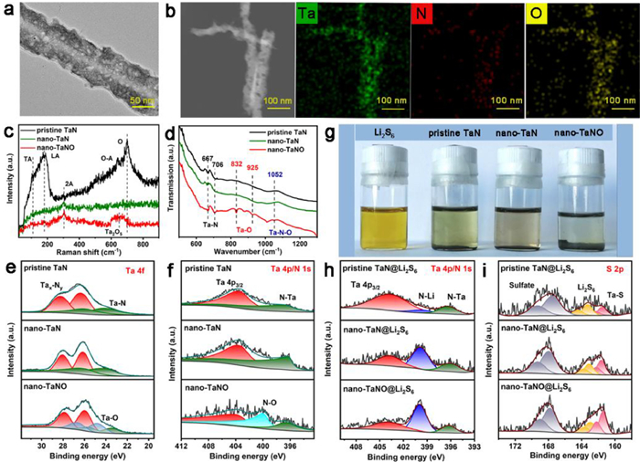
Inspired by these considerations, herein, we report a facile oxygen (O) doping route to synthesize high-density O-doped porous nano-TaN (nano-TaNO) for achieving fast LiPS interconversion. As illustrated in Fig. S1 (Supporting information), nano-TaN and nano-TaNO were synthesized by high-energy ultrasonicating pristine TaN in 1-methyl-2-pyrrolidone (NMP) and saturated KOH solution, respectively. The transmission electron microscopy (TEM) image in Fig. S2a (Supporting information) shows that the morphology of pristine TaN is irregular particle with the size of 0.5~3 µm, while the size of nano-TaN (Fig. S2b in Supporting information) obtained after ultrasonic process is largely downsized to submicron (0.1~1 µm). Furthermore, from the obvious contrast change from dark to light, nano-TaN possesses thinner thickness than the pristine TaN, confirming the morphology change from bulk to nanosheet. Interestingly, the morphology of the nano-TaNO with alkali etching (Fig. 1a) changes to nanorod with zigzag edges, and voids are formed in the whole structure, which is expected to increase the active sites for the subsequent sulfur redox. Meantime, energy-dispersive X-ray spectrometry (EDS) mappings in Fig. 1b show homogeneous distributions of Ta, N and O elements in nano-TaNO, different from nano-TaN and pristine TaN (Fig. S3 in Supporting information), verifying a successful O incorporation in nano-TaNO.
Figure 1
Figure 1.
(a) TEM images of nano-TaNO. (b) EDS elemental mappings of Ta, N and O in nano-TaNO. (c) Raman and (d) FTIR spectra of pristine TaN, nano-TaN and nano-TaNO. (e) Ta 4f and (f) N 1s XPS spectra of the three samples. (g) Photographs of different samples soaked in Li2S6 solutions. (h) N 1s and (i) S 2p XPS spectra of the three samples after Li2S6 adsorption.
The X-ray diffraction (XRD) patterns in Fig. S4 (Supporting information) show that the diffraction intensity of nano-TaNO is much weakened due to the defects generated by the alkali etching. Notably, a small peak at 24.2° appears in nano-TaNO, which can be assigned to (110) of TaON [12], confirming the introduction of O into the nano-TaN. Furthermore, Raman spectrum of the pristine TaN (Fig. 1c) shows two peaks at around 120 and 175 cm–1, which are corresponding to the first-order transverse acoustic (TA) and longitudinal acoustic (LA) modes of TaN, respectively [13,14]. For nano-TaN and nano-TaNO, large part of the Raman peaks are missing, which is attributed to the decrease in thickness compared to the pristine TaN. Notably, there is a peak at approximately 660 cm–1 in the spectrum of the nano-TaNO, which is identified to Ta2O5 [15]. The Fourier transform infrared (FTIR) spectrum (Fig. 1d) also validates the introduction of O, based on the appearance of the Ta–O (832 and 925 cm–1) and Ta–N–O (1052 cm–1) bonds in nano-TaNO [16].
The surface states and chemical environments were further probed by X-ray photoelectron spectroscopy (XPS), where the Ta 4f XPS spectrum of the pristine TaN in Fig. 1e can be fitted to two pairs of Ta 4f7/2, 5/2 peaks, which are assigned to Tax–Ny (28.3/26.4 eV) and Ta–N (26.1/24.2 eV), respectively [17]. In contrast, a pair of peaks located at 26.8 and 24.8 eV, referring to Ta–O bond [18], are formed in nano-TaNO, and the Ta 4f peaks shift toward lower binding energy due to the electron transfer from O to Ta. Additionally, for the N 1s XPS spectrum (Fig. 1f), a new peak at ~400.1 eV appears in nano-TaNO, which can be ascribed to N–O bond [6]. The high content of O in nano-TaNO can be proved by the higher Ta–O and N–O XPS intensities (Fig. S5 in Supporting information) comparing to those in a weakly oxidized nano-TaNO sample, which was treated in half saturated KOH solution. The above results prove a large amount of O atom is successfully doped in nano-TaNO, and chemically interacts with Ta and N, respectively.
The good adsorption ability of nano-TaNO towards LiPSs can be proved by the fact that the brown color of the Li2S6 solution is fading to the largest extent with the addition of nano-TaNO (Fig. 1g). The XPS was also used to further explore their interaction. As shown in Fig. 1h, down-shift of Ta 4p3/2 and N 1s occurs in all three samples compared to the original ones (Fig. 1f), proving the electron shift from the Li in Li2S6 to N in TaN. It is worth noting that the peak at ~400.0 eV is enhanced for nano-TaN and nano-TaNO, especially for nano-TaNO, which is attributed to the N–Li bond originated from the chemical interaction between the N in nano-TaNO and Li in Li2S6. Simultaneously, the Ta−S peaks (Fig. 1i) [19] of the nano-TaNO@Li2S6 (161.4/162.2 eV) are the strongest among the spectra, and the Ta 4f peaks of the nano-TaNO shift to lower binding energy compared to the pristine TaN and nano-TaN (Fig. S6 in Supporting information), indicating the enhanced interaction between S and Ta in nano-TaNO.
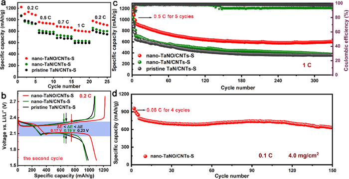
To evaluate the effects that the pristine TaN, nano-TaN, weakly oxidized nano-TaNO and nano-TaNO exerted on the electrochemical performances of sulfur, typical coin cells with a corresponding sulfur cathode were assembled and tested. In Fig. 2a, the nano-TaNO/CNTs-S cathode shows the higher specific capacities, namely 1220, 960, 884, 818 mAh/g at 0.2, 0.5, 0.7 and 1 C, respectively, than the pristine TaN/CNTs-S (1063, 772, 679 and 592 mAh/g), nano-TaN/CNTs-S (1076, 818, 727 and 632 mAh/g) and the weakly oxidized nano-TaNO/CNTs-S (1221, 892, 812 and 741 mAh/g, Fig. S7a in Supporting information) cathodes. When the current density decreases to 0.2 C, its capacity turns back to 979 mAh/g, which also presents the highest retention. The highest specific capacities in nano-TaNO-based cell prove that the high-density O doping is favorable for the pronounced sulfur redox kinetics. The lowest voltage gap (ΔE) values [20] in the nano-TaNO-based cell (Fig. 2b) imply that it possesses the smallest polarization throughout the test, further demonstrating the nano-TaN with high-density O doping presents the most positive effect for promoting the redox of LiPSs. The nano-TaNO/CNTs-S cathode also presents impressive cycling performance as shown in Fig. 2c. The cell exhibits 929 and 604 mAh/g at 1 C for the initial and 330th cycles, respectively, with a low loss rate of 0.11% per cycle, which is lower than that of the pristine TaN (0.13%), nano-TaN (0.14%) and weakly oxidized nano-TaN (0.18%, Fig. S7c in Supporting information). For the future application of Li–S batteries, cathode with high sulfur loading should never be neglected. Thus, the nano-TaNO/CNTs-S electrode with sulfur loading of 4.0 mg/cm2 was explored (Fig. 2d), which exhibits a high initial capacity of 786 mAh/g at 0.1 C, and 634 mAh/g after 150 cycles with an average decay rate of 0.12%, proving its potential for practical application.
Figure 2
Figure 2.
(a) Rate performances of three electrodes under various current densities. (b) Charge/discharge profiles at 0.2 C with different cathodes for the second cycle. (c) Long-term cycling performance at 1 C with different cathodes. (d) Cycling performance of nano-TaNO/CNTs-S electrode under the high sulfur loading of 4.0 mg/cm2 at 0.1 C.
The favorable effect of nano-TaNO on improving the sulfur conversion kinetics was further systematically investigated. From the cyclic voltammetry (CV) results (Fig. 3a and Fig. S8 in Supporting information), the obvious separated anodic peaks (P3 and P4) in the nano-TaNO-based cell proves the fast kinetics enabled by the O-doped nano-TaN [21]. Moreover, the nano-TaNO-based cell exhibits Tafel slope of 57, 52 and 75 mV/dec for P1, P2 and P3 peaks (Figs. 3b and c, Fig. S9 in Supporting information), which is smaller than those of pristine TaN (143, 189 and 180 mV/dec) and nano-TaN (99, 80 and 130 mV/dec), suggesting the favorable electron transfer efficiency and its high kinetic activity for sulfur specie conversion [22]. For further analysis in Fig. S10 (Supporting information), it is found that the cell with nano-TaNO exhibits the highest oxidation/reduction current, together with the highest reduction potentials (P1, P2) and the lowest oxidation potential (P3), further elucidating that the reaction kinetics in both cathodic and anodic processes are enhanced. The fast kinetics achieved by nano-TaNO is also supported by electrochemical impedance spectroscopy (EIS) results at open-circuit voltage (OCV) and after 20 cycles (Fig. S11 in Supporting information). The values of the charge transfer resistance (Rct) and the solid electrolyte interphase resistance (RSEI) [23] at OCV and the 20th cycle are summarized in Table S1 (Supporting information), showing that the nano-TaNO-based cell exhibits the lowest resistance, which is beneficial for reducing polarization in the electrochemical tests. Besides, Li+ diffusion coefficients (DLi) of these three cells were fitted (Figs. 3d and e) and calculated based on Warburg line in EIS (calculation details and results are given in Table S2 in Supporting information), and the results claim that the values of DLi follow the order of nano-TaNO > nano-TaN > pristine TaN. The results prove that conversion kinetics and Li+ diffusion for the nano-TaNO-based cell are the fastest among these three cells, which would be beneficial for expediting the Li2S precipitation and recycling process.
Figure 3
Figure 3.
(a) CV curves of different cathodes at 0.1 mV/s. (b, c) Tafel plots calculated from the P1 and P2 peaks in (a). (d, e) The linear relationship between ω−1/2 and the Warburg resistance from the EIS. (f–h) Potentiostatic discharge profiles of Li−S batteries at 2.04 V on three electrodes with Li2S8 for evaluating Li2S deposition. (i) Responsivity time, current density and capacity of Li2S precipitation on different electrodes.
Potentiostatic nucleation experiments were conducted to disclose the liquid-solid conversion kinetics [24] with the pristine TaN/CNTs, nano-TaN/CNTs and nano-TaNO/CNTs electrodes, and the Li2S deposition profiles with analysis are shown in Figs. 3f–i. It is found that the nano-TaNO electrode exhibits higher current response (0.18 mA/cm2) compared to the pristine TaN (0.11 mA/cm2) and nano-TaN (0.12 mA/cm2). Equally, the highest Li2S precipitation capacity (180.2 mAh/g) and earliest response of Li2S (8317 s) in the nano-TaNO are also presented in contrast to the pristine TaN (130.7 mAh/g, 14487 s) and the nano-TaN (136.4 mAh/g, 13023 s), indicating a more thorough liquid-solid transformation of sulfur species is achieved by nano-TaNO. Additionally, the enhanced liquid-liquid polysulfide conversion was also evaluated by the curves of the symmetric cells (Fig. S12 in Supporting information). These results illustrate that the O doping in TaN favors the electrocatalytic activity for both liquid-solid and liquid-liquid conversion, consequently, a more thorough sulfur redox can be provided in nano-TaNO-based cell.
In situ chemical spectroscopy can be a powerful tool to do mechanistic analysis of Li−S battery. To gain insight on how sulfur specie progresses over potential in real time, in situ UV−vis monitoring was firstly carried out at characteristic discharge potentials. In Fig. S13 (Supporting information), the UV−vis spectra recorded on three electrodes (nano-TaNO/CNTs, nano-TaN/CNTs, pristine TaN/CNTs) in Li2S8 solution show the peaks corresponding to the presence of S82− (492 nm), S62− (475 nm), S42− (420 nm) and S3*− radical (617 nm) [25]. A quantitative estimation of the reaction rate of sulfur conversion on each electrode was realized by calculating the normalized absorbance change rate of the LiPSs peaks as a function of potential (Figs. 4a–c, Figs. S14 and S15 in Supporting information). Accompanied by a drop in cell potential, the absorbance intensities of S82−, S62− and S42− species decrease faster on nano-TaNO/CNTs surface than on the other two electrodes (nano-TaN/CNTs, pristine TaN/CNTs), while the reduction of long-chain LiPSs leads to the more significant increase of the short-chain S3*− signals on nano-TaNO/CNTs electrode. This indicates nano-TaNO can accelerate the conversion of long-chain LiPSs to short-chain S3*− more efficiently, probably owing to the doping of O in nano-TaN. It is known that S3*− radical as an important intermediate could accelerate the conversion from LiPSs to Li2S2/Li2S by providing additional pathway [26], where O defect is believed to firstly chemisorb S62− to form S52−, then the unstable S52− reacts with S8 to form S3*− radical; after gaining one electron and one Li+, S3*− is converted to S32−, then S32− may react with S42− to form S62− and S2−, as illustrated in Fig. 4d. In situ Raman studies in Figs. 4e–g further support the relationship of S3*−chemisorption and O doping. It is obvious that during discharge on nano-TaNO/CNTs-S electrode, S8 and S62− intensities gradually reduce, S3*− signal appears around 2.2 V, but it decreases from 2.0 V, instead, S22− signal emerges between 2.0 V and 1.8 V [21,27]. In comparison, only the reduction of S8 intensity is observed on pristine TaN/CNTs-S and nano-TaN/CNTs-S electrodes without the participation of S3*−, suggesting a lower conversion efficiency for LiPSs.
Figure 4
Figure 4.
The Normalized absorbance of (a) S82−, (b) S62−, (c) S3*− on three electrodes in Li2S8 electrolyte during discharge. (d) The proposed sulfur reduction reaction routes for the Li–S battery with the nano-TaNO. In situ Raman spectra of (e) nano-TaNO/CNTs-S, (f) nano-TaN/CNTs-S and (g) pristine TaN/CNTs-S electrodes at different discharge depths. Quasi-in situ (h, i) Li 1s and (j, k) N 1s XPS spectra of nano-TaNO/CNTs-S and pristine TaN/CNTs-S cathodes after discharging to specific states.
Besides the sulfur conversion mechanism, the chemical evolution of Li on the nano-TaNO-based cathode during discharge was also investigated by quasi-in situ XPS analysis. In Figs. 4h and i, the Li 1s signal due to the Li−S bond of LiPSs exhibits at 55.8 eV [28]. The shoulder peak at 54.8 eV could be assigned to Li−N/Li−O bond for nano-TaNO/CNTs-S electrode (Fig. 4h) and Li−N bond for pristine TaN/CNTs-S electrode (Fig. 4i), respectively. The N−Li peaks dominate the N 1s spectra of both electrodes (Figs. 4j and k). It is visible that there is a shift of Li−S peak to lower binding energy during discharge on the nano-TaNO/CNTs-S electrode. By contrast, the pristine TaN/CNTs-S electrode shows very little change of the Li 1s peak during discharge. These results indicate that there are more significant chemical interactions at the nano-TaNO/LiPS interface, where Li atoms of LiPSs are extracting electrons from nano-TaNO, thus favoring the reduction of LiPSs. It is important to point that the shift of the N−Li/N−O peak in the N 1s spectra of nano-TaNO/CNTs-S electrode could be caused by Li−O interaction during discharge, since almost no shifts of the N−Li peak are observed in the N 1s spectra of pristine TaN/CNTs-S electrode (Fig. 4k) but a higher binding energy shift in O 1s spectra of nano-TaNO/CNTs-S electrode in Fig. S16 (Supporting information). As a result, the electronic interaction between nano-TaNO and LiPSs should be via Li−O but not Li−N bond.
In conclusion, we propose high-density O defect-engineered nano-TaN with abundant nanopores as a catalyst on cathode to accelerate sulfur conversion kinetics. The nano-TaNO possesses more exposed surface and porous structure for sulfur storage and charge/Li+ transfer to improve electrochemical polarization. Simultaneously, the nano-TaNO with high-density O active sites can strongly chemisorb LiPSs through Li–O and Ta–S interactions and impel the formation of S3*− radicals to accelerate their conversion, resulting in higher capacity and cycling properties even at high sulfur loading.
Declaration of competing interest
The authors declare that they have no known competing financial interests or personal relationships that could have appeared to influence the work reported in this paper.
Acknowledgments
This work was supported in part by the National Natural Science Foundation of China (Nos. 22109119, 51972238 and U21A2081), the Natural Science Foundation of Zhejiang Province (Nos. LQ19B030006 and LQ22B030003) and the Major Scientific and Technological Innovation Project of Wenzhou City (No. ZG2021013).
Supplementary materials
Supplementary material associated with this article can be found, in the online version, at doi:10.1016/j.cclet.2022.107911.
Y. Zhang, S. Yang, S. Zhou, et al., Chem. Commun. 57 (2021) 3255–3258. doi: 10.1039/D0CC08377A
[22]
B.Q. Li, L. Kong, C.X. Zhao, et al., InfoMat 1 (2019) 533–541. doi: 10.1002/inf2.12056
[23]
S. Drvarič Talian, G. Kapun, J. Moškon, et al., Chem. Mater. 31 (2019) 9012–9023. doi: 10.1021/acs.chemmater.9b03255
[24]
Y.Q. Peng, M. Zhao, Z.X. Chen, et al., Batteries Supercaps 5 (2021) e202100359.
[25]
S. Zhou, S. Yang, D. Cai, et al., Adv. Sci. 9 (2022) 2104205. doi: 10.1002/advs.202104205
[26]
R. Xu, H. Tang, Y. Zhou, et al., Chem. Sci. 13 (2022) 6224–6232. doi: 10.1039/D2SC01353C
[27]
M. Hagen, P. Schiffels, M. Hammer, et al., J. Electrochem. Soc. 160 (2013) A1205–A1214. doi: 10.1149/2.045308jes
[28]
W. Chen, T.Y. Lei, T. Qian, et al., Adv. Energy Mater. 8 (2018) 1702889. doi: 10.1002/aenm.201702889
Figure 1
(a) TEM images of nano-TaNO. (b) EDS elemental mappings of Ta, N and O in nano-TaNO. (c) Raman and (d) FTIR spectra of pristine TaN, nano-TaN and nano-TaNO. (e) Ta 4f and (f) N 1s XPS spectra of the three samples. (g) Photographs of different samples soaked in Li2S6 solutions. (h) N 1s and (i) S 2p XPS spectra of the three samples after Li2S6 adsorption.
Figure 2
(a) Rate performances of three electrodes under various current densities. (b) Charge/discharge profiles at 0.2 C with different cathodes for the second cycle. (c) Long-term cycling performance at 1 C with different cathodes. (d) Cycling performance of nano-TaNO/CNTs-S electrode under the high sulfur loading of 4.0 mg/cm2 at 0.1 C.
Figure 3
(a) CV curves of different cathodes at 0.1 mV/s. (b, c) Tafel plots calculated from the P1 and P2 peaks in (a). (d, e) The linear relationship between ω−1/2 and the Warburg resistance from the EIS. (f–h) Potentiostatic discharge profiles of Li−S batteries at 2.04 V on three electrodes with Li2S8 for evaluating Li2S deposition. (i) Responsivity time, current density and capacity of Li2S precipitation on different electrodes.
Figure 4
The Normalized absorbance of (a) S82−, (b) S62−, (c) S3*− on three electrodes in Li2S8 electrolyte during discharge. (d) The proposed sulfur reduction reaction routes for the Li–S battery with the nano-TaNO. In situ Raman spectra of (e) nano-TaNO/CNTs-S, (f) nano-TaN/CNTs-S and (g) pristine TaN/CNTs-S electrodes at different discharge depths. Quasi-in situ (h, i) Li 1s and (j, k) N 1s XPS spectra of nano-TaNO/CNTs-S and pristine TaN/CNTs-S cathodes after discharging to specific states.

 DownLoad:


 下载:
下载:


 下载:
下载:
