Citation:
Yongjie Cui, Peipei Zhu, Xinxin Xia, Xinhui Lu, Xunfan Liao, Yiwang Chen. Carbazolebis(thiadiazole)-core based non-fused ring electron acceptors for efficient organic solar cells[J]. Chinese Chemical Letters,
2023, 34(8): 107902.
doi:
10.1016/j.cclet.2022.107902
Carbazolebis(thiadiazole)-core based non-fused ring electron acceptors for efficient organic solar cells
English
Carbazolebis(thiadiazole)-core based non-fused ring electron acceptors for efficient organic solar cells
State Key Laboratory for Modification of Chemical Fibers and Polymer Materials and College of Materials Science and Engineering, Donghua University, Shanghai 201620, China
b.
National Engineering Research Center for Carbohydrate Synthesis/Key Lab of Fluorine and Silicon for Energy Materials and Chemistry of Ministry of Education, College of Chemistry and Chemical Engineering, Jiangxi Normal University, Nanchang 330022, China
c.
Department of Physics, Chinese University of Hong Kong, New Territories, Hong Kong 999077, China
* Corresponding authors at: State Key Laboratory for Modification of Chemical Fibers and Polymer Materials and College of Materials Science and Engineering
ywchen@ncu.edu.cn (Y. Chen). 1 These authors contributed equally to this work.
Received Date:
02 July 2022 Accepted Date:
11 October 2022 Revised Date:
17 August 2022 Available Online:
15 August 2023
Abstract:
Non-fused ring electron acceptors (NFREAs) have a broad application prospect in the commercialization of organic solar cells (OSCs) due to the advantages of simple synthesis and low cost. The selection of intermediate block cores of non-fused frameworks and the establishment of the relationship between molecular structure and device performance are crucial for the realization of high-performance OSCs. Herein, two A-D-A'-D-A type NFREAs namely CBTBO-4F and CBTBO-4Cl, constructed with a novel electron-deficient block unit N-(2-butyloctyl)-carbazole[3,4-c: 5,6-c]bis[1,2,5]thiadiazole (CBT) and bridging unit 4,4-bis(2-ethylhexyl)-4H-cyclopenta[2,1-b: 3,4-b']dithiophene (DTC) coupling with different terminals (IC-2F/2Cl), were designed and synthesized. The two NFREAs feature broad and strong photoresponse from 500 nm to 900 nm due to the strong intramolecular charge transfer characteristics. Compared with CBTBO-4F, CBTBO-4Cl shows better molecular planarity, stronger crystallinity, more ordered molecular stacking, larger van der Waals surface, lower energy level and better active layer morphology, contributing to much better charge separation and transport behaviors in its based devices. As a result, the CBTBO-4Cl based device obtains a higher power conversion efficiency of 10.18% with an open-circuit voltage of 0.80 V and a short-circuit current density of 21.20 mA/cm2. These results not only demonstrate the great potential of CBT, a new building block of the benzothiazole family, in the construction of high-performance organic conjugated semiconductors, but also suggest that the terminal chlorination is an effective strategy to improve device performance.
As one of the photovoltaic technologies that can effectively utilize clean and renewable energy, organic solar cells (OSCs) have attracted extensive attention of researchers because of their advantages of light weight, low cost, solution processing, large-area preparation [1-3]. Over the past decades, with the design and development of non-fullerene acceptors, the power conversion efficiency (PCE) of OSCs has been significantly improved. This breakthrough structure design mainly relies on A-DA'D-A type architecture, including a polyheterocyclic fused-ring units as the intermediate core, such as thienothiophen[3.2-b]pyrolobenzothiadiazole (TPBT) [4-6] and thienothiophen[3.2-b]-pyrolo benzotriazole (TPBTZ) [7-10]. These non-fullerene fused ring electron acceptors (FREAs) have wide and strong absorption, improved aggregation performance, multi charge transfer channels and enhanced electron mobility, resulting in outstanding PCE of more than 19% [11-13]. Despite the excellent photovoltaic performance, fused ring electron acceptors generally exhibit complex synthesis routes, low yield and high cost, which limits the commercial application process of OSCs.
Compared with the FREAs, non-fused ring electron acceptors (NFREAs) with simple aromatic compounds have become a research hotspot recently because they meet the requirement of cost-effectiveness [14-18]. Inspired by the highly efficient A-DA'D-A type fused ring acceptors widely used in OSCs, the architecture based on A-D-A'-D-A type was designed and applied for NFREA. Among the NFREAs, A is commonly used in IC-2F and IC-2Cl (2-(5,6-difluoro/dichloro-3-oxo-2,3-dihydro-1H-inden-1-ylidene)malononitrile), and D generally selects 4,4-bis(2-ethylhexyl)-4H-cyclopenta[2,1-b: 3,4-b']dithiophene (DTC) [19-21], 4,4-bis(2-ethylhexyl)-4H-silolo[3,2-b: 4,5-b']dithiophene (DTS) [22] and 4-(2-ethylhexyl)-4H-dithieno[3,2-b: 2′,3′-d]pyrrole (DTP) [23-25]. Particularly, the choice of A' is a key issue, which is vital for adjusting the energy level, light absorption capacity, intramolecular interaction, and intermolecular stacking behavior. The introduced intermediate block core A' can generally form non-covalent conformation locks (such as N…S, O…S and F…S) to ensure conformational stability. Benzodithiophene (BT) is a strong electron-withdrawing unit with two conformation locking sites (N), which has been widely investigated and successfully modified to form several related structures [26-29], as shown in Fig. 1. Recently, BT based NFREAs have obtained an excellent device PCE. Based on these results and combined with the diversified modification of BT, a novel block unit N-alkyl-carbazole [3,4-c: 5,6-c]bis[1,2,5]thiadiazole (CBT) has been designed by our group [30,31]. From the results of conformation optimization, the molecular planarity parameters (MPP) [32] of BT, naphtho[1,2-c: 5,6-c']bis([1,2,5]thiadiazole) (NBT) and CBT are all 0, indicating that they have good planarity and rigidity, while the MPP value of 4,4′-bibenzo[c][1,2,5]thiadiazole (BBT) is larger, and thus it is not suitable for constructing NFREAs. Moreover, molecular energy level simulation shows that BT and NBT have deeper highest occupied molecular orbital (HOMO) and lowest unoccupied molecular orbital (LUMO) and stronger electron-withdrawing ability compared with CBT, which is not conducive to improving the open circuit voltage (VOC) of corresponding devices, which is consistent with the results reported in the literatures [33,34]. Meanwhile, the molecular surface electrostatic potential (ESP) of CBT shows more red and yellow regions with the minimal overall average ESP value, indicating that CBT has a weak electron-withdrawing ability. When the CBT unit acts as the intermediate block core of A-D-A'-D-A type NFREAs, it will help to promote the intramolecular charge transfer (ICT), and thus contribute to broaden the absorption and enhance the short-circuit current (JSC) of the device. N from the CBT can form conformational lock with surrounding S to maintain good molecular planarity, and thus ensure better molecular stacking. The carbazole structure contained in the CBT has good stability. In addition, the alkyl chain connected to pyrrole-N can further adjust the solubility and accumulation of molecules. Therefore, CBT has great potential in constructing NFREAs.
Figure 1
Figure 1.
Molecular design inspiration from BT, BBT, NBT to CBT (from top to bottom are chemical structures and DFT-calculated molecular planarity parameters (MPP), energy level and molecular surface electrostatic potential at the B3LYP/6-31G(d, p)) accompanied with fluorination and chlorination and the derived non-fused ring electron acceptors in this work.
Based on the above analysis, we designed and synthesized two A-D-A'-D-A type NFREAs namely CBTBO-4F and CBTBO-4Cl with N-(2-butyloctyl)-carbazole[3,4-c: 5,6-c]bis[1,2,5]thiadiazole (CBT) as the intermediate core A' and IC-2F/2Cl as the terminal unit (Fig. 1). The molecular conformation simulation results show that CBTBO-4Cl has better molecular planarity. The molecular ESP results show that they have similar overall average ESP value, but the larger atomic radius of chlorine atom increases the van der Waals surface area of molecules, thus increasing the contact area with donors, which is conducive to improving the intermolecular charge separation and transport. As expected, the facile synthesized NFREAs CBTBO-4F and CBTBO-4Cl exhibit strong absorption at 500-900 nm, which can be well matched with the polymer donor PBDB-T. Notably, CBTBO-4Cl shows strong intermolecular aggregation effect from solution to film. Moreover, according to the morphology analysis and molecular stacking analysis, it is found that PBDB-T: CBTBO-4Cl exhibits better active layer morphology and larger crystal coherent length after thermal annealing, which is conducive to improving the charge transfer in the active layer. Therefore, PBDB-T: CBTBO-4Cl based device obtained a high PCE of 10.18% with a VOC of 0.80 V and a JSC of 21.20 mA/cm2. The results demonstrate that the selection of electron-deficient unit CBT as central core A' provides meaningful molecular design guidance for efficient OSCs.
The synthetic routes of CBTBO-4F and CBTBO-4Cl are depicted in Scheme 1. The detailed synthetic procedures are described in Supporting information. The key compound 4 was synthesized according to the previously reported procedures [30]. The intermediate 6 was obtained by Stille coupling of the compound 5 and DTC, and the intermediate 7 with aryl aldehyde was synthesized via Vilsmeier-Haack reaction. Finally, the two target products, CBTBO-4F and CBTBO-4Cl, were obtained by Knoevenagel condensation under mild conditions. All intermediates and target products were obtained with a high yield. Then, the chemical structure of CBTBO-4F and CBTBO-4Cl were characterized by 1H NMR and matrix-assisted laser desorption ionization time-of-flight mass spectroscopy (MALDI-TOF MS), demonstrating the high purity of the materials. CBTBO-4F and CBTBO-4Cl can be dissolved in chloroform and chlorobenzene, but the solubility of CBTBO-4Cl is slightly poor, they can meet better film-forming quality by heating and stirring. In order to explore the thermodynamic behavior of CBTBO-4F and CBTBO-4Cl, TGA test was carried out, as shown in Fig. S1 (Supporting information). The thermal decomposition temperatures (5% weight loss) of CBTBO-4F and CBTBO-4Cl are 334 and 339 ℃, respectively, indicating that both have good thermal stability and meet the temperature requirements of device preparation.
Scheme 1
Scheme 1.
Synthesis routes and chemical structures of CBTBO-4F and CBTBO-4Cl.
The initial structures of CBTBO-4F and CBTBO-4Cl were optimized and energy levels were calculated by density functional theory (DFT) at the B3LYP/6-31G(d, p), the alkyl side chains were replaced by methyl to save calculation time, as shown in Fig. 2a and Fig. S2 (Supporting information). The optimal conformations of CBTBO-4F and CBTBO-4Cl molecules are W-shaped, while CBTBO-4Cl has good molecular planarity relative to CBTBO-4F from the top view and side view of the optimal conformation, which is conducive to improving the intermolecular interaction. Moreover, the calculated results show that the S-N distances in CBTBO-4F and CBTBO-4Cl are 2.84 and 2.83 Å, respectively, which are much smaller than the van der Waals radius of the S-N atomic center of 3.35 Å, indicating that there are S…N conformational locks in both molecules, which is helpful to maintain strong molecular rigidity and planarity [35]. The simulation results of molecular energy levels show that CBTBO-4Cl has deeper HOMO and LUMO energy level. The molecular surface ESP (isosurface = 0.001 a.u.) is simulated based on the optimal conformation, as shown in Figs. 2b–d and the relevant parameters are summarized in Table S1 (Supporting information). We can see that the two molecular surfaces are mainly blue and green, indicating that the surface has a positive potential distribution, and a strong intermolecular electric field is formed with the electron rich donor, which is conducive to the generation of charge [36-38]. Furthermore, CBTBO-4Cl has a large molecular van der Waals surface, which is profit to the formation of a large contact area with the donor, thus promoting exciton dissociation. CBTBO-4F and CBTBO-4Cl have similar overall average ESP values. The difference is that the introduction of chlorine atoms improves the surface ESP distribution value and the maximum ESP value of atoms, contributing to the formation of strong intermolecular interactions.
Figure 2
Figure 2.
(a) Optimized geometric structures, (b) molecular ESP, (c) ESP area distributions and (d) averaged atom ESP values of CBTBO-4F and CBTBO-4Cl.
The ultraviolet-visible (UV-vis) absorption spectra of CBTBO-4F and CBTBO-4Cl in dilute solution and film is shown in Figs. 3a and b, and the corresponding data are presented in Table 1. In dilute solution and thin film, the maximum absorption peak of CBTBO-4Cl is red shifted relative to CBTBO-4F, which is attributed to the strong intramolecular charge transfer characteristics of CBTBO-4Cl and the strong intermolecular π-π interaction caused by its better molecular planarity. They show strong absorption at 500-900 nm and the absorption edges of CBTBO-4F and CBTBO-4Cl are 885 and 891 nm, respectively, and thus can form a good light absorption complementary with PBDB-T, which is conductive to broadening the absorption and enhancing the JSC. Notably, CBTBO-4F and CBTBO-4Cl have only one obvious charge transfer characteristic peak (0-0) at 724 and 728 nm in dilute solution, respectively, while there emerges a shoulder peak (0-1) in pure film, and the ratio of the absorption intensity of the two peaks gradually increases from 0.99 to 1.05, indicating that the intermolecular aggregation effect is improved from solution to film. As can be seen from Fig. 3c, when CBTBO-4F and CBTBO-4Cl are blended with PBDB-T, they show wide absorption at 300–900 nm, while PBDB-T: CBTBO-4Cl presents obviously stronger absorption in 650–900 nm compared to PBDB-T: CBTBO-4F. Accordingly, PBDB-T: CBTBO-4Cl blend film can harvest more sunlight, which is conducive to increasing JSC. Cyclic voltammetry is used to measure the energy levels of CBTBO-4F, CBTBO-4Cl and PBDB-T, as shown in Fig. S3 (Supporting information) and Fig. 3d. The HOMO and LUMO energy levels of CBTBO-4F and CBTBO-4Cl are calculated to be −5.31/−3.89 eV and −5.45/−x3.90 eV, respectively. In addition, the HOMO and LUMO of PBDB-T are calculated to be -5.35 and -3.53 eV, respectively. Therefore, the energy levels of CBTBO-4Cl can match well with PBDB-T, which is benefit for charge separation and transport. It is worth noting that the HOMO energy level difference between PBDB-T and CBTBO-4F is negative, which is not conducive to charge separation and thus leads to less exciton dissociation efficiency.
Figure 3
Figure 3.
UV-vis absorption spectra of CBTBO-4F and CBTBO-4Cl in (a) dilute solution and (b) pure film. (c) PBDB-T: CBTBO-4F and PBDB-T: CBTBO-4Cl blend film. (d) The energy level diagrams of the materials.
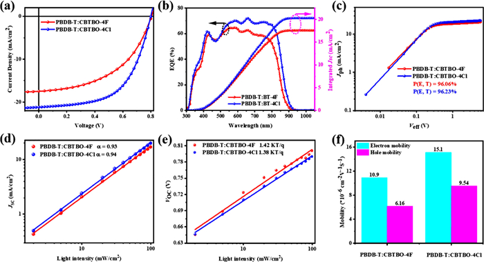
To investigate the photovoltaic properties of CBTBO-4F and CBTBO-4Cl, OSCs were fabricated with a conventional configuration of ITO/PEDOT: PSS/Active layer/PDINO/Ag. The optimal D: A ratio of the active layer is 1:1.2, and then the device is optimized by solvent, spin-coating speed and thermal annealing. The relevant device performance parameters are summarized in Tables S2–S4 (Supporting information). It can be seen from the J-V curve (Fig. 4a) and Table 2 that PBDB-T: CBTBO-4F based devices have achieved a VOC of 0.81 V, a JSC of 17.95 mA/cm2, a fill factor (FF) of 48.48% and a PCE of 7.05%. However, the JSC of the PBDB-T: CBTBO-4Cl based device is significantly enhanced to 21.20 mA/cm2, which was relatively balanced with the VOC (0.80 V), and the FF was also increased to 60.01%, resulting in a final PCE of 10.18%. From the external quantum efficiency (EQE) curve of the devices (Fig. 4b), it can be seen that PBDB-T: CBTBO-4Cl has stronger EQE response in the range of 500-900 nm, contributing to higher JSC. Further, the corresponding integral JSC values are 17.58 and 20.29 mA/cm2, respectively, meeting the deviation of 5% compared with the JSC values measured from the J-V curves.
Figure 4
Figure 4.
(a) J-V characteristics, (b) EQE spectra, (c) Jph-Veff curves, (d) JSC-Plight, (e) VOC-Plight characteristics and (f) carrier mobility of devices based on PBDB-T: CBTBO-4F and PBDB-T: CBTBO-4Cl optimal devices.
In order to explore the charge collection probability of PBDB-T: CBTBO-4F and PBDB-T: CBTBO-4Cl based devices, the relative effective voltage (Veff) of photocurrent (Jph) was tested [39,40], as shown in Fig. 4c. Here, Jph is defined as JL - JD, JL and JD represent photocurrent density under light and dark conditions, respectively. The Veff is defined as V0 − Vappl, where V0 is the voltage when JL = JD, and Vappl is the applied bias voltage. When Veff reaches 2 V, Jph reaches saturation (Jsat), and the charge collection efficiency (Pcoll) is calculated by Jph/Jsat. PBDB-T: CBTBO-4Cl based devices obtained 96.23% of Pcoll, which is slightly higher than that of PBDB-T: CBTBO-4F. In order to further explore the charge recombination behavior, the light intensity dependence tests of JSC and VOC were carried out. Generally, the relationship between JSC, VOC and light intensity (Plight) can be described as: JSC∝Plightα and VOC∝nkT/qln(Plight), where k, T and q are the Boltzmann constant, absolute temperature, and the element charge, respectively. Moreover, when α and n are closer to 1, it indicates that bimolecular recombination and trap-assisted recombination in the device are lower. It can be seen from Fig. 4d that the fitted α values are 0.93 and 0.94, respectively, indicating that PBDB-T: CBTBO-4Cl based device has lower bimolecular recombination, which is conducive to increasing FF. The curve fitting (Fig. 4e) between VOC and Plight shows that the n of PBDB-T: CBTBO-4F and PBDB-T: CBTBO-4Cl based devices are 1.42 and 1.38, respectively, indicating that PBDB-T: CBTBO-4Cl based device has lower trap-assisted recombination. Moreover, carrier mobility is determined by SCLC method [41-43] with the device structure of ITO/PEDOT: PSS/active layer/MoO3/Ag for hole mobility (μh) and ITO/ZnO/active layer/PDINO/Al for electron mobility (μe), respectively, as shown in Fig. 4f and Fig. S4 (Supporting information), and the corresponding data are summarized in Table S5 (Supporting information). The μe and μh of PBDB-T: CBTBO-4Cl are 15.1 × 10⁻⁶ and 9.54 × 10⁻⁶ cm2 V−1 s−1, respectively, which are significantly higher than those of PBDB-T: CBTBO-4F. Meanwhile, the μe/μh value of PBDB-T: CBTBO-4Cl is smaller than PBDB-T: CBTBO-4F counterpart, indicating a more balanced charge transfer, which is consistent with the results of larger FF of PBDB-T: CBTBO-4Cl based devices.
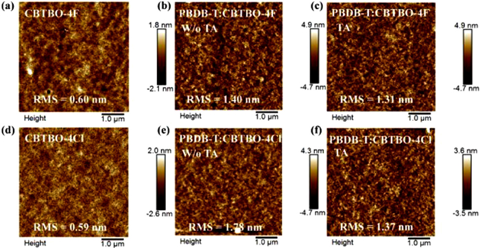
The difference of photovoltaic performance is generally related to the morphology of the active layer. Therefore, atomic force microscopy (AFM) is used to study the morphology of pure films and blend films. As shown in Fig. 5, the pure films of CBTBO-4F and CBTBO-4Cl exhibit similar root mean-square (RMS) close to 0.6 nm, indicating that they have good film-forming properties. When CBTBO-4F and CBTBO-4Cl are blended with PBDB-T, it is found that the RMS of PBDB-T: CBTBO-4F is 1.40 nm before annealing and decrease after annealing. Similar result is also found in PBDB-T: CBTBO-4Cl. The difference was that the RMS of PBDB-T: CBTBO-4Cl changed greatly before and after annealing, indicating that the morphology of the active layer was more effectively improved. In order to explore the differences in the morphology of the blend films, the Flory-Huggins interaction parameter (χ) is obtained through water and diiodomethane contact angle technology for evaluating the miscibility [44,45], as shown in Fig. S5 (Supporting information), and the corresponding data are presented in Table S6 (Supporting information). The results show that the surface energies (γ) of PBDB-T, CBTBO-4F and CBTBO-4Cl are 38.36 mN/m, 45.78 mN/m and 46.32 mN/m, respectively. χ could be obtained by the formula of , and the corresponding values are 0.32 and 0.37, respectively, indicating that CBTBO-4F and PBDB-T have better miscibility. However, the improved miscibility causes smaller phase separation (Figs. 5c and f), which is not conducive to exciton dissociation and charge transport.
Figure 5
Figure 5.
AFM images of (a) CBTBO-4F, (b) PBDB-T: CBTBO-4F without annealing, (c) PBDB-T: CBTBO-4F with annealing, (d) CBTBO-4Cl, (e) PBDB-T: CBTBO-4Cl without annealing, and (f) PBDB-T: CBTBO-4Cl with annealing.
Grazing incidence wide-angle X-ray scatting is used to investigate the molecular stacking and crystallization properties in pure and blend films. 2D GIWAXS patterns and 1D line cuts in plane and out of plane are showed in Figs. 6a–g, and the detailed parameters are summarized in Table S7 (Supporting information). CBTBO-4F presents a lamellar peak at 0.410 Å along the in plane with a (010) peak at 1.750 Å along the out of plane (OOP), indicating that the CBTBO-4F pure film tends to face-on orientation. Similarly, CBTBO-4Cl also tends to face-on orientation, while the crystal coherence length (CCL) of CBTBO-4Cl is greater than that of CBTBO-4F, indicating that CBTBO-4Cl has stronger crystallization properties. In PBDB-T: CBTBO-4F blend film, there is a (010) peak at 1.735 Å in OOP direction with a (100) lamellar stacking peak both in plane and out of plane, indicating that there are two orientations of face-on and edge-on in the blend film. After thermal annealing, the CCL of the blend film is significantly improved, which is conducive to the charge transport in the active layer. For PBDB-T: CBTBO-4Cl blend film, the intensity of the (100) peak along the OOP direction decreased significantly after thermal annealing, while the intensity of the diffraction peak at (010) increased, indicating that the blend films tend to face-on orientation. Moreover, the CCL of PBDB-T: CBTBO-4Cl blend film is also significantly enhanced, thereby improving its crystallinity. Compared with PBDB-T: CBTBO-4F blend film, the CCL of PBDB-T: CBTBO-4Cl blend film is obviously larger, which is conducive to charge transfer and is consistent with the higher carrier mobility and higher JSC of the devices.
Figure 6
Figure 6.
GIWAXS images of the (a) CBTBO-4F, (b) PBDB-T: CBTBO-4F without annealing, (c) PBDB-T: CBTBO-4F with annealing, (d) CBTBO-4Cl, (e) PBDB-T: CBTBO-4Cl without annealing, and (f) PBDB-T: CBTBO-4Cl with annealing. (g) The corresponding intensity profiles along the out of plane (black lines) and in plane (red lines) direction.
In conclusion, two A-D-A'-D-A type non-fused ring electron acceptors (NFREAs), i.e., CBTBO-4F and CBTBO-4Cl have been successfully synthesized based on a novel intermediate electron-deficient core CBT. CBTBO-4F and CBTBO-4Cl both exhibit strong absorption at 500-900 nm, forming complementary absorption with the polymer donor PBDB-T. Besides, CBTBO-4Cl shows deeper HOMO and LUMO energy levels relative to CBTBO-4F due to the dipole moment of C-Cl is larger than that of C-F. Additionally, CBTBO-4Cl exhibits stronger S…N conformation lock in the molecule compared to CBTBO-4F, thus obtaining better molecular planarity and rigidity. CBTBO-4Cl also has a larger van der Waals surface area and ESP maximum value relative to CBTBO-4F, which is conducive to increasing the interaction with donors. Therefore, the PBDB-T: CBTBO-4Cl blend film exhibits better morphology and larger CCL than that of PBDB-T: CBTBO-4F blend film, which is conducive to charge transfer. Moreover, the charge recombination of the PBDB-T: CBTBO-4Cl device is reduced, while the carrier mobility as well as charge collection efficiency are improved, resulting in the improvement of the JSC and FF of the devices. As a result, the PCE of PBDB-T: CBTBO-4Cl based device is 10.18% and much higher than that of PBDB-T: CBTBO-4F (7.05%). Although this performance is still lag behinds the current most efficient NFREAs, the novel building block CBT features great potential in the construction of high-performance active layer materials of OSCs. Beyond that this work also establishes a relationship between the molecular structure and the device performance, and provides certain guiding significance for the selection of A' unit in A-D-A'-D-A type NFREAs.
Declaration of competing interest
The authors declare that they have no known competing financial interests or personal relationships that could have appeared to influence the work reported in this paper.
Acknowledgments
This work was financially supported by the National Natural Science Foundation of China (NSFC, Nos. 51973032, 21905043 and 51833004), the "Chenguang Program" supported by Shanghai Education Development Foundation and Shanghai Municipal Education Commission (No. 19CG36), the Jiangxi Provincial Natural Science Foundation (Nos. 20212ACB203005 and 20212BAB213018), the Thousand Talents Plan of Jiangxi Province (No. jxsq2019101051), and the Jiangxi Provincial Education Department Science and Technology Research Foundation (No. GJJ210310). X. Xia and X. Lu acknowledge the financial support from Research Grants Council (RGC) of Hong Kong (General Research Fund No. 14303519). Y. Chen expresses thanks for the support from the Fundamental Research Funds for the Central Universities and Graduate Student Innovation Fund of Donghua University (No. CUSF-DH-D-2021008).
Supplementary materials
Supplementary material associated with this article can be found, in the online version, at doi:10.1016/j.cclet.2022.107902.
[1]
X. Liao, Q. Xie, Y. Guo, et al., Energy Environ. Sci. 15 (2022) 384–394. doi: 10.1039/D1EE02858H
Figure 1
Molecular design inspiration from BT, BBT, NBT to CBT (from top to bottom are chemical structures and DFT-calculated molecular planarity parameters (MPP), energy level and molecular surface electrostatic potential at the B3LYP/6-31G(d, p)) accompanied with fluorination and chlorination and the derived non-fused ring electron acceptors in this work.
Figure 3
UV-vis absorption spectra of CBTBO-4F and CBTBO-4Cl in (a) dilute solution and (b) pure film. (c) PBDB-T: CBTBO-4F and PBDB-T: CBTBO-4Cl blend film. (d) The energy level diagrams of the materials.
Figure 5
AFM images of (a) CBTBO-4F, (b) PBDB-T: CBTBO-4F without annealing, (c) PBDB-T: CBTBO-4F with annealing, (d) CBTBO-4Cl, (e) PBDB-T: CBTBO-4Cl without annealing, and (f) PBDB-T: CBTBO-4Cl with annealing.
Figure 6
GIWAXS images of the (a) CBTBO-4F, (b) PBDB-T: CBTBO-4F without annealing, (c) PBDB-T: CBTBO-4F with annealing, (d) CBTBO-4Cl, (e) PBDB-T: CBTBO-4Cl without annealing, and (f) PBDB-T: CBTBO-4Cl with annealing. (g) The corresponding intensity profiles along the out of plane (black lines) and in plane (red lines) direction.


 DownLoad:


 下载:
下载:


 下载:
下载:
