College of Chemistry and Chemical Engineering, Qingdao University, Qingdao 266071, China
b.
College of Electronic and Optical Engineering & College of Flexible Electronics (Future Technology), Nanjing University of Posts and Telecommunications, Nanjing 210023, China
Received Date:
09 February 2022 Accepted Date:
02 May 2022 Revised Date:
11 April 2022 Available Online:
15 March 2023
Abstract:
The regulation of the basic properties of atom-economic catalysts at the atomic scale and atomic-level insights into the underlying mechanism of catalysis are less explored. We engineer the surface of vertical immobilized MoS2 on dispersible TiO2 nanofibers via atomic subtraction to precisely manipulate active sites at the atomic level. The photocatalytic performances of TiO2@MoS2 after H2 reduction towards the hydrogen production under visible light irradiation (> 420 nm) are about 4 times that of TiO2@MoS2 before H2 reduction. Importantly, the enhanced stability of TiO2@MoS2 lasts for at least 30 h. Promising catalytic activity that is attributed to omnidirectional exposed active sites located defects, edges, corners that are transformed from the subtractive atomic sites could be exhumed comprehensively. This work will provide an intriguing and effective approach on tuning electronic structures for optimizing the catalytic activity at the atomic level by atom elimination strategy. To get rid of a few atomics on the surface of atomically-thin MoS2 nanosheet could be a prudent avenue for enabling the basal plane of MoS2 catalytically active.
In recent years, among the non-Pt based electrocatalysts, the layered transition metal dichalcogenides (TMDs) nanomaterials with MoS2 as representatives, is considered promising candidates for hydrogen evolution reaction (HER) electrocatalyst [1, 2]. Herein, the key to increasing the number of active sites of the MoS2 HER catalyst is divided into: (1) producing monolayer MoS2 nanosheets [3]; (2) exposing under-coordinated edge sites by designing high porous 3D hierarchical architecture [4–6]; (3) engendering the distorted structures of MoS2 with crystalline defects, dislocations, or discontinuities [7-9]. All above strategies has mainly focused on controlling the size to be as thin as possible or enabling an inert basal plane in order to maximize the density of active sites in MoS2. Each strategy for increasing catalytic performance is rather limited, so it still calls for revolutionary designs of catalytic materials to integrate all above startegies to make all multifunctional active sites on MoS2-based catalysts.
As for the normal MoS2 nanosheets, only edge site is catalytic active, while the planar zone is catalytically inert. The existing modification methods to active the MoS2 base plane can be divided into two categories. One is to generate and expose as many active edge sites as possible through the design of nanostructures, that is, to increase the proportion of active edge sites. Another way is to change the nature of the inert plane area to make it an active area. Both of which can enhance the overall catalytic effect. Preparing nano-scale MoS2 to expose more edges to the outside is an effective way to improve its electrocatalytic hydrogen production activity. However, nano-scale MoS2 is easy to agglomerate, and it is possible to synthesize a layered MoS2 electrocatalyst with rich edges with a certain material as the substrate. In previous reports, we have realized that the MoS2 nanosheets grow vertically on the surface of TiO2 nanofibers to fully expose the edge active sites. In order to further improve the HER activity, we also transformed the vertically grown 2H-MoS2 into 1T-MoS2. As well known, the construction of defects is believed to play an important role in improving catalyst activity. vertically grown 2H-MoS2 [10-16]. The introduction of defects into the vertically grown 2H-MoS2 is rarely reported. At present, the reported defects of two-dimensional materials are mainly produced by ion/electron beam irradiation, plasma etching, laser irradiation, strain, hydrogen annealing, and substoichiometric growth [17-22]. Herein, we propose an ideal model of atomically-thin vertically grown MoS2 nanosheet with defects as an excellent platform to activate the catalytic activity of inert in-plane atoms. When the tri-layer S–Mo–S sheet being created with atomic subtraction, it gives rise to nanosheets with low-coordination step-edges, kinks, corner atoms. The unique structure with ultimate specific surface area can bring on tremendous atomic and electronic structural variations and helps to create unprecedented opportunities to increase the amounts of active sites for HER efficiency. Vertically grown 2H-MoS2 with defects of base plane could maximize the density of active sites, thereby greatly improving the HER performance of the catalyst [23-25].
The vertically-oriented two-dimensional nanosheet structure can produce abundant active sites due to its inherent large specific surface area and rich edge structure. The internal new edges (tears, pinholes and defects) were created and the MoS2 was successfully implanted in the 2H-MoS2 nanosheet matrix. All above could increase the number of ''active sites'' that results from the S or Mo vacancies exited by hydrothermal synthesis and then H2 reduction. Meanwhile, distorted structures and interlayer decoupling were also possibly produced from Peierls distortion to decrease their high surface energy then realize the stable units. This green, safe, highly efficient and ultralow-cost approach paves the way to engineer MoS2 with desirable maximizing active sits for hydrogen evolution catalysis.
We firstly synthesized vertically MoS2 nanosheets rooting into porous 1D TiO2 nanofibers (TiO2@V-MoS2) via a simple hydrothermal method [26-30]. Using porous TiO2 nanofibers as nucleation centers for the growth of MoS2 nanosheets was aimed to control the lateral growth of MoS2 without expansion in the c-axis direction. Figs. 1a and b shows dark field FESEM-STEM images and the transmission electron microscope (TEM) of the TiO2@MoS2 forming a core/shell structure. It is clearly revealed that the cross-linked MoS2 nanosheets with a lateral size of about 100 nm are vertically grown on the surface of 1D TiO2 nanofibers substrate. The MoS2 nanosheets are transparent, wrinkled, and curly, indicative of their ultrathin 2D nature. Such unique characteristics is ideal for HER as the vertical orientation of the MoS2 nanosheets and the resultant open structure can provide lots of tunnels for fast transfer of electron/ion.
Figure 1
Figure 1.
(a) Dark field FESEM-STEM image of vertically MoS2 nanosheet on TiO2 nanofibers (TiO2@V-MoS2). (b) TEM of TiO2@V-MoS2. (c) Schematic illustration of fabricate vertically holly MoS2 nanosheet on TiO2 nanofibers (TiO2@VH-MoS2).
The simplified synthesis process of H2 thermal reduction of TiO2@V-MoS2 at optimized temperature of 500 ℃ in H2 for 3 h is illustrated in Fig. 1c. A facile thermally H2 treatment of MoS2 resulting in S vacancies, Mo vacancies even hole.
Figs. 2a and b show that TEM images of the TiO2@V-MoS2. The ultra-thin MoS2 layer grows almost vertically on the surface of TiO2 nanofibers. It can be seen very clearly that the MoS2 nanosheets are few or even single layers. The discrete and disordered growth of MoS2 nanosheets prevented face-to-face restacking. The freely suspended MoS2 exhibited random elastic deformation and distortion edges, which is in the favor of the stability of 2D materials [31-35]. Fig. 2c showed the MoS2 perfect crystal of TiO2@V-MoS2. In Fig. 2d, the discretely and disorderly MoS2 sheets along the axes of TiO2 nanofibers further distorted enabling a high structural stability after H2 reduction and holey MoS2 nanosheets was obtained (Fig. 2e) Simultaneously, some atomic-scale holes configurated in the basal planes of MoS2 nanosheets, whose morphology looks like MoS2 nanomesh. HRTEM image in Fig. 2f provides further insight into the typical low-coordinated structure of the holey MoS2. Newly low coordination-structured active edge sites and activated basal planes, which are expected to boost the intrinsic HER activity of 2H-MoS2 [36-39].
Figure 2
Figure 2.
TEM and TEM images of (a–c) TiO2@V-MoS2, (d–f) TiO2@VH-MoS2.
The samples were investigated by using XPS to further confirm whether vacancies and holes were introduced or not after H2 thermal reduction. All XPS spectra were calibrated using the C 1s peak at 284.8 eV. As shown in Fig. 3a, after H2 thermal reduction, both Mo 3d and S 2p peaks in the XPS spectra broadens and shift to the lower binding energies, which could be attributed to the formation of S-vacancies or Mo-vacancies [17-19]. To identify the quantity of vacancies, the XPS peak area ratio of S 2p to Mo 3d states for TiO2@VH-MoS2 was measured with normalizing the value of the S/Mo ratio to 2.0 as a reference. As a result, the S/Mo ratio decreased from 2.0 to 1.85 after H2 thermal reduction. These results give powerful evidence for the existence of atomic vacancies and hole. From the above discussion, the novel VH-MoS2 can significantly increase the exposure of active sites due to the formation of defects and holes on the basal surface. The zeta potentials of samples in aqueous solution were investigated to further confirm this conclusion. A more negative zeta-potential means the catalyst could provide more active sites for the reduction of protons to generate H2 [20-23]. As shown in Fig. 3b, the VH-MoS2 reveals more negative zeta potentials than the H-MoS2 nanosheets in the pH range of 2-12. That is to say, an increased exposure edge sites and vacancies are existed on the defective MoS2 with hole which allow to achieve an enhanced HER efficiency. Figs. 3c and d further show the atoms near the hole become much more negative than the prefect MoS2. In Fig. 3e, shows that the density of states (DOS) of MoS2 with Mo defects crossing the Fermi level. Band gap is decreased which may promote the conductivity. Electrons are more quickly transported to the active site to facilitate catalytic hydrogen production. This electronic effect will strengthen the H adsorption and offer an increased H coverage on the edge sites.
Figure 3
Figure 3.
(a) High-resolution XPS spectra of Mo 3d in TiO2@V-MoS2 and TiO2@VH-MoS2. (b) Zeta potentials of TiO2@V-MoS2 and TiO2@VH-MoS2 as a function of pH in aqueous dispersions. (c, d) Computational unit cell of MoS2 and MoS2 with Mo defects. (e) DOS of MoS2 and MoS2 with Mo defects.
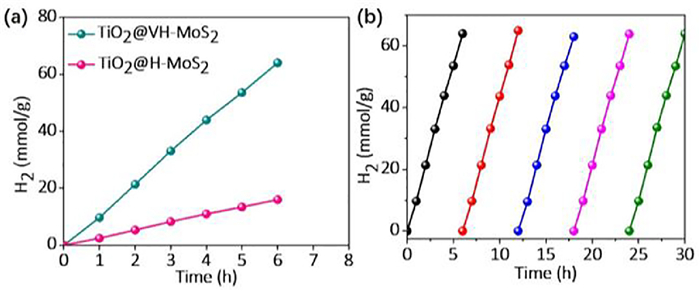
Photocatalytic H2 evolution performance of TiO2@V-MoS2 and TiO2@VH-MoS2 are evaluated under visible-light irradiation (λ ≥ 420 nm) with Eosin Y (EY) as the photosensitizer and triethanolamine (TEOA) as a sacrificial electron donor (SED). As indicated in Fig. 4a, it can be clearly seen that all the samples can efficiently generate H2, suggesting that the MoS2 itself could also work well as a cocatalyst in a dye-sensitization based photochemical system. The TiO2@VH-MoS2 shows a significantly enhanced the rate of H2 evolution average 9.8 mmol/h, which is about 4 times higher than that of the TiO2@V-MoS2 (average 2.5 mmol/h) under the same conditions. Furthermore, the H2 evolution rate of the MoS2 TiO2@VH-MoS2 is very stable during long-term test (Fig. 4b). Even after 30 h, the H2 generation rate in the fifth cycle shows no significant decrease comparing with the first cycle, demonstrating the TiO2@VH-MoS2 has good stability for photocatalytic HER.
Figure 4
Figure 4.
(a) H2 evolution rates on the EY-sensitized photocatalysts in 80 mL of 15% (v/v) TEOA aqueous solution under visible light irradiation (≥420 nm). Catalysts: 20 mg and EY: 20 mg. (b) Stability testing over EY-sensitized TiO2@VH-MoS2 for H2 generation under the same condition.
Furthermore, the detail mechanism of photocatalytic H2 production on the TiO2@VH-MoS2 can be explained according to the proposed mechanism as depicted in Fig. 5. The detached electron cloud of LUMO and HOMO in EY (Fig. 5a) is instrumental in the separation of e− and h+. The adsorption behaviors of EY on MoS2 (both perfect and Mo defect) are further calculated (Fig. 5b). The equation of Eabs = Etotal − EMoS2 − EEY was used to measure the adsorption energy of EY on two kinds of MoS2, Eabs represents for the absorption energy, Etotal is the total energy of the compounds, EMoS2 stands for the energy of the MoS2, and EEY means the energy per EY molecule. From our calculation results, the Eabs for the MoS2 and Mo defect MoS2 are −0.21 and −0.67 eV, respectively, indicating MoS2 with Mo defect could absorb EY molecule more thermodynamically. That is, the calculations verified that the MoS2 with Mo defect is more appropriate for EY molecule adsorb. Figs. S1–S3 (Supporting Information) showed that all the MoS2 with virous defects could absorb EY with stronger force than the prefect MoS2. To further determine the contribution of EY to hydrogen evolution, the frontier orbitals relative energy levels position of EY and of MoS2 were analyzed. As shown in Fig. 5c, the LUMO and HOMO levels of EY are −0.82 and 1.29 eV. The conduction band (CB) composed of Mo 4d states that lie just above the Fermi level leading to a narrow band gap. Due to the LUMO levels of EY (−0.82 eV) are more negative than the CB levels of MoS2, the photo-excited electrons in EY could be injected into the CBs of MoS2 easily during HER. After the absorption of light by EY, the EY dye molecules transform into singlet excited state (EY1*), and then subsequently yield a lowest-lying triplet excited-state EY3*via an efficient intersystem crossing (ISC) [28]. The oxidation EY3* can be reductively quenched by sacrificial donor TEOA to form EY−*. The electrons of EY−* are transferred to active sites of the VH-MoS2, leading to spatially separation of photogenerated charges, and then reduce the absorbed H2O or proton to form H0. It has been reported that only the metallic edges of 2H-MoS2 are catalytically active, while the basal planes are inert [39-42]. Thus, the electrons transfer from EY−* to the VH-MoS2 are easier than that of the prefect MoS2 nanosheets due to possibly giving additional active sites located at the whole MoS2 nanosheets, leading to the higher HER efficiency on the VH-MoS2.
Figure 5
Figure 5.
(a) Frontier electron densities of LUMO and HOMO of EY. (b) The structure and the corresponding absorption energy of MoS2 (Mo defect) with a EY molecule. (c) Energy band illustration of EY and MoS2.
We engineer the surface of vertical immobilized MoS2 on dispersible TiO2 nanofibers via a facile thermally H2 treatment to precisely manipulate active sites at the atomic level. The regulation of the basic properties of atom-economic catalysts at the atomic scale and atomic-level insights into the underlying mechanism of catalysis are well explored. Promising catalytic activity that is attributed to omnidirectional exposed active sites located defects, edges, corners that are transformed from the subtractive atomic sites could be exhumed comprehensively. The photocatalytic performances of TiO2@MoS2 after thermally H2 treatment towards the HER under visible light irradiation (> 420 nm) have been greatly improved. This study here deepens the understanding of the effects of micro-nano structure and defects on the HER performance of MoS2 and also provide new insights into developing high-performance catalyst for water splitting.
Declaration of competing interest
We declare that we have no financial and personal relationships with other people or organizations that can inappropriately influence our work, there is no professional or other personal interest of any nature or kind in any product, service and/or company that could be construed as influencing the position presented in, or the review of, the manuscript entitled.
Acknowledgments
This work was financially supported by the Natural Science Foundation of China (No. 51902101), the Youth Natural Science Foundation of Hunan Province (No. 2021JJ540044), Natural Science Foundation of Jiangsu Province (No. BK20201381), Science Foundation of Nanjing University of Posts and Telecommunications (No. NY219144).
Supplementary materials
Supplementary material associated with this article can be found, in the online version, at doi:10.1016/j.cclet.2022.05.003.
Figure 1
(a) Dark field FESEM-STEM image of vertically MoS2 nanosheet on TiO2 nanofibers (TiO2@V-MoS2). (b) TEM of TiO2@V-MoS2. (c) Schematic illustration of fabricate vertically holly MoS2 nanosheet on TiO2 nanofibers (TiO2@VH-MoS2).
Figure 3
(a) High-resolution XPS spectra of Mo 3d in TiO2@V-MoS2 and TiO2@VH-MoS2. (b) Zeta potentials of TiO2@V-MoS2 and TiO2@VH-MoS2 as a function of pH in aqueous dispersions. (c, d) Computational unit cell of MoS2 and MoS2 with Mo defects. (e) DOS of MoS2 and MoS2 with Mo defects.
Figure 4
(a) H2 evolution rates on the EY-sensitized photocatalysts in 80 mL of 15% (v/v) TEOA aqueous solution under visible light irradiation (≥420 nm). Catalysts: 20 mg and EY: 20 mg. (b) Stability testing over EY-sensitized TiO2@VH-MoS2 for H2 generation under the same condition.
Figure 5
(a) Frontier electron densities of LUMO and HOMO of EY. (b) The structure and the corresponding absorption energy of MoS2 (Mo defect) with a EY molecule. (c) Energy band illustration of EY and MoS2.


 DownLoad:


 下载:
下载:


 下载:
下载:
