
Scheme 1.
Illustration of the preparation process of the hierarchical macroporous–mesoporous silica film using zinc oxide nanorod array as macroporous template and CTAB surfactant as mesoporous template.
Uniform hierarchical silica film with perpendicular macroporous channels and accessible ordered mesopores for biomolecule separation
Xiaodan Su , Jun Tao , Sui Chen , Peng Xu , Dan Wang , Zhaogang Teng

Porous silica materials have attracted increasing attention for various applications such as separations [1], catalysis [2, 3], chemical sensing [4], and biomedicine [5-7]. Porous silica with different morphologies including sphere, film, monolith, rod, fiber have been synthesized [8-17]. Among them, mesoporous silica films are particularly important because they are promising for separation, electronic, optical, and electrochemical applications [18-23].
Previously, porous silica films have been prepared via surfactant-directed sol–gel process at oil-water [24] or air–water [25] interfaces. However, the direction of channels in the films produced by the methods is parallel to the film surfaces [26-30]. The accessibility and performance of these films for practical applications is thus limited to the unaccessible pores. The development of methods for film made of perpendicular channels is in much higher demand due to their huge potential in future applications including catalyst support films, high-sensitive chemical sensors, ultra-high-density recording media, size-selective separation, etc. In spite of extensive efforts on worldwide, successful synthesis of porous films with perpendicular channels are much less than expected and remain a major challenging issue so far. Some strategies to control porous orientation through chemical modification of solid–liquid interfaces [31] or dimensional confinement of the silica species by anodized porous alumina films [32] or block copolymers [33, 34] have been reported. Furthermore, strong external magnetic fields or electro-assisted method also have been used to orient the direction of pores [35, 36]. However, the prepared porous films either show non-perpendicular channels, disordered pores, discontinuous macro-morphology, lower stability or accompanied by powdery samples on the surface. Moreover, these reported methods for preparing the mesoporous films often require complex processes and special equipments. To date, the preparation of films with perpendicular accessible channels is still a big challenge.
Herein, we demonstrate that silica films with perpendicular macroporous channels and accessible ordered mesopores can be conveniently prepared by using zinc oxide array as template. The preparation process for the hierarchical macroporous–mesoporous silica film is shown in Scheme 1. First, mesostructured silica is homogeneously deposited on zinc oxide array. Afterwards, the ZnO nanorod and the surfactant were removed by a one-step extraction method in an acidic solution. The method provides a good opportunity for preparing hierarchical silica films with perpendicular mesochannels. The morphology and mesostructure of the synthesized silica films have been investigated by scanning electron microscopy (SEM) and transmission electron microscopy (TEM). Due to the hierarchical macroporous–mesoporous structures, the silica films show excellent separation ability for proteins with different sizes.
Chemicals and Materials: Anhydrous ethanol, tetraethoxysilane (TEOS, ≥28.4%), cetyltrimethylammonium bromide (CTAB, ≥99%), ammonia aqueous solution (25%–28%) were purchased from Sinopharm Chemical Reagent Co., Ltd. (Shanghai, China). Millipore water with a resistivity of greater than 10 MΩ cm were used in all experiments. Zinc oxide nanorod array was obtained from the Advanced Materials Laboratory of Fudan University. Cytochrome c (Cyt c) and bovine serum albumin (BSA) were purchased from Aldrich (St. Louis, MO, USA).
Preparation: The mesoporous silica film was growth on zinc oxide roads array in ethanol aqueous solution using cetyltrimethylammonium bromide (CTAB) as a surfactant. In brief, 15 mL of ethanol, 25 mL of water, 0.04 mL of TEOS, 0.08 g of CTAB, and 0.005 mL of aqueous ammonia were mixed under stirring. The zinc oxide nanoarray was then immersed in the mixed solution and allowed to stand at 60 ℃ for 72 h. Afterward, the substrate was thoroughly rinsed with water and dried at 100 ℃ overnight. The surfactant and zinc oxide were removed by a one-step extraction method, in which the film was immersed in 30 mL of an ethanol solution containing 0.1 mol/L hydrochloric acid overnight. The silica film was finally obtained after rinsing with water.
Protein separation: 500 μL of cytochrome c (2 ×10⁻⁵ mol/L) and 500μL of bovine serum albumin (2 ×10⁻⁵ mol/L) were mixed, transferred to the of silica film (2 × 2 cm), and then rinsed the film using 1 mL of water. The absorbance of the eluent was measured using UV–vis spectrophotometer.
Characterization: Scanning electron microscope (SEM) images were taken using a Hitachi S4800 (Japan) field emission scanning electron microscope at an acceleration voltage of 1 kV. Transmission electron microscopy (TEM) images were taken using Hitachi H-8100 (Japan) and JEOL 2100 F (Japan) microscopes at an acceleration voltage of 200 kV. For TEM measurement, the silica films were scraped from substrate, dispersed in ethanol, and supported on a carbon-coated Cu grid. The X-ray diffraction (XRD) pattern of the silica film was measured using a Bruker model D8 diffractometer (40 kV, 40 mA) in continuous scan mode with a scan range of 1–10° and a scan interval of 0.02°.
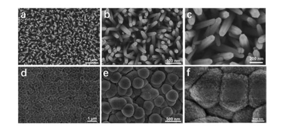
Zinc oxide nanorod array was used as macroporous template for the silica film. SEM images show that the zinc oxide nanorods were standing on the substrate with a certain angle of inclination (Figs. 1a and b). High-magnification SEM images show that the zinc oxide nanorods have a hexagonal columnar structure with a diameter of about 120 nm (Fig. 1c). The silica precursors were catalytically hydrolyzed by ammonia and assembled with surfactant on the zinc oxide nanorods to form mesostructures. After growth of silica on the zinc oxide nanorod, the film maintains continuous (Fig. 1d). SEM images show that the surface of the silica film has a tightly packed hemispherical morphology (Figs. 1e and f). The diameter of hemispheres on the film surface is measured to be approximately 365 nm. TEM images show that silica shell layers are uniformly coated on the surface of the nanorods (Fig. 2a), which is in agreement with the SEM results. The thickness of the silica shell is measured to be approximately 150 nm. It is noted that the mesopores of the silica shell are perpendicularly oriented to the zinc oxide nanorods with openings on the surfaces (Fig. 2b), which facilitates the transfer for guest molecules.

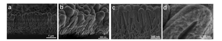
Cross-section SEM images of the hierarchical silica film show an uniform thickness of approximately 2 μm (Figs. 3a and b). The SEM images show that the silica film retains intact morphology and structure after peeling off. Obviously, the silica film has abundant channels which are perpendicular to their surface. The length and width of the channels are measured to be approximately 1.8 μm and 80 nm, respectively. The SEM images show that the silica film is closely packed by inverted U-shaped rods (Fig. 3c). The shell thickness of the inverted U-shaped rods is measured to be approximately 150 nm. Since the zinc oxide nanorods have a certain oblique angle, the large pores of the obtained silica film are also staggered inside the film. At the same time, the macroporous channels show an angular structure (Fig. 3d), further indicating that the channels is originated from the zinc oxide nanorods.
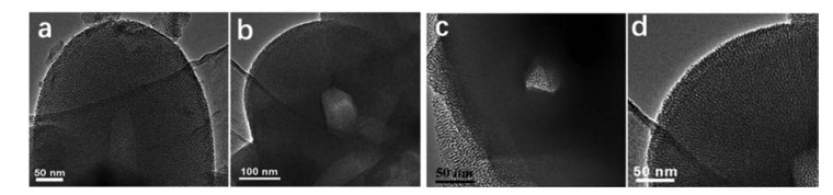
TEM images show that the zinc oxide nanorods are completely removed using 0.1 mol/L HCl (Fig. 4a), and the prepared silica film remained in its original morphology. TEM images show that the diameter of the macropores is measured to be 76 nm (Fig. 4b), which is consistent to the SEM results. The large pores in the silica film have a clear hexagonal structure (Figs. 4b and c). High-magnification TEM images show that the silica shells have a mesoporous structure (Fig. 4d), which are connected to the large channels, indicating they are accessible (Figs. 5 and 6).
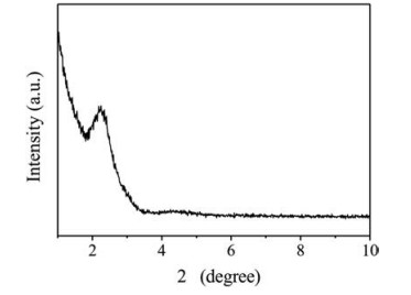
The XRD pattern of the hierarchical macroporous–mesoporous silica film shows two diffraction peaks, which correspond to the 10 and 11 diffraction of p6mm symmetry, indicating that the silica film has an ordered two-dimensional hexagonal structure. The XRD result is consistent with that of MCM-41 mesoporous silica material, demonstrating that the silica film has a similar mesostructure to MCM-41.
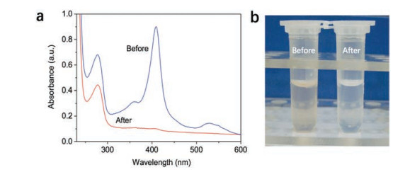
The mesoporous-macroporous silica films were used for separation of Cyt c and BSA. The molecular sizes for Cyt c and BSA are 2.5 nm × 2.5 nm × 3.7 nm and 4.0 nm × 4.0 nm × 14.0 nm, respectively. The UV–vis spectrum of the mixed proteins shows two absorption peaks at 409 and 277 nm, corresponding to of Cyt c and BSA, respectively. The mixed Cyt c and BSA were then adsorbed using the film and eluted. Notably, there was no Cyt c in the eluate, indicating that the mesoporous-macroporous silica film captured the Cyt c, due to the size of the Cyt c is smaller than the mesoporous channel of the silica film. In contrast, The eluate recovers 66% pure BSA, suggesting the silica film can efficiently separate Cyt c and BSA. The optical images show that the solution of Cyt c and BSA has a light brown color before separation, which becomes transparent after separation due to the Cyt c is captured by the silica film.
In summary, hierarchical macroporous–mesoporous silica film has been successfully synthesized using zinc oxide nanorod array as macroporous template and CTAB surfactant as mesoporous template. The silica film has an uniform thickness of approximately 2 μm and large perpendicular channels with a length of 1.8 μm and a width of 80 nm. The silica film has an ordered and accessible mesoporous pores, which are connected with the large channels. Separation experiment demonstrates that this macroporous– mesoporous silica film can effectively separate biomolecules with different sizes.
We greatly appreciate the financial support from the Natural Science Foundation of Jiangsu Province (No. BK20160017), and the National Natural Science Foundation of China (No. 21603106).
M.N. Sarvi, T.B. Bee, C.K. Gooi, et al., Chem. Eng. J. 235(2014) 244-251. doi: 10.1016/j.cej.2013.09.036
W. Sheng, W. Wei, J.J. Li, et al., Appl. Surf. Sci. 387(2016) 1116-1124. doi: 10.1016/j.apsusc.2016.07.061
Y. Tao, E.G. Ju, J.S. Ren, X.G. Qu, Adv. Mater. 27(2015) 1097-1104. doi: 10.1002/adma.201405105
Y.C. Lee, S. Dutta, K.C.W. Wu, ChemSusChem 7(2014) 3241-3246. doi: 10.1002/cssc.v7.12
S.Y. Tan, C. Teh, C.Y. Ang, et al., Nanoscale 9(2017) 2253-2261. doi: 10.1039/C6NR08869D
Y. Wang, H.C. Gu, Adv. Mater. 27(2015) 576-585. doi: 10.1002/adma.v27.3
W.X. Gao, Y.L. Hu, L. Xu, et al., Chin. Chem. Lett. 29(2018) 1795-1798. doi: 10.1016/j.cclet.2018.05.022
S.M. Lai, H.Y. Lai, M.Y. Chou, Microporous Mesoporous Mater.196(2014) 31-40. doi: 10.1016/j.micromeso.2014.04.043
R. Hikosaka, F. Nagata, M. Tomita, K. Kato, Colloids Surf. B 140(2016) 262-268. doi: 10.1016/j.colsurfb.2015.12.054
T.N. Ng, X.Q. Chenac, K.L. Yeung, RSC Adv. 5(2011) 13331-13340. https://core.ac.uk/display/34052717
N.Ž. Knežević, J.O. Durand, Nanoscale 7(2015) 2199-2209. doi: 10.1039/C4NR06114D
J. Wei, Z.K. Sun, W. Luo, et al., J. Am. Chem. Soc. 139(2017) 1706-1713. doi: 10.1021/jacs.6b11411
X.Q. Wang, Y. Zhang, W. Luo, et al., Chem. Mater. 28(2016) 2356-2362. doi: 10.1021/acs.chemmater.6b00499
D. Gu, H. Bongard, Y. Meng, et al., Chem. Mater. 22(2010) 4828-4833. doi: 10.1021/cm101648y
W. Luo, T. Zhao, Y.H. Li, et al., J. Am. Chem. Soc. 138(2016) 12586-12595. doi: 10.1021/jacs.6b07355
K.P. Yuan, R.C. Che, Q. Cao, et al., ACS Appl. Mater. Interfaces 7(2015) 5312-5319. doi: 10.1021/am508683p
Y. Liu, Y.H. Deng, Z.K. Sun, et al., Small 9(2013) 2702-2708. doi: 10.1002/smll.v9.16
K.E. Shopsowitz, H. Qi, W.Y. Hamad, M.J. MacLachlan, Nature 468(2010) 422-426. doi: 10.1038/nature09540
Z.G. Teng, G.F. Zheng, Y.Q. Dou, et al., Angew. Chem. Int. Ed. 51(2012) 2173-2177. doi: 10.1002/anie.201108748
T. Nasir, G. Herzog, M. Hebrant, et al., ACS Sens. 3(2018) 484-493. doi: 10.1021/acssensors.7b00920
S.J. Guo, Z.W. Wang, Z.Y. Xu, et al., Chin. Chem. Lett. 28(2017) 2143-2146. doi: 10.1016/j.cclet.2017.08.041
D.K. Shen, G. Wang, Z.C. Liu, et al., J. Am. Chem. Soc. 140(2018) 11402-11407. doi: 10.1021/jacs.8b06609
Y.P. Liu, D.K. Shen, G. Chen, et al., Adv. Mater. 29(2017) 1702274. doi: 10.1002/adma.201702274
H. Yang, N. Coombs, I. Sokolov, G.A. Ozin, Nature 381(1996) 589-592. doi: 10.1038/381589a0
S. Schacht, Q. Huo, I.G. Voigt-Martin, G.D. Stucky, F. Schuth, Science 723(1996) 768-773. https://www.ncbi.nlm.nih.gov/pubmed/8670410
Z.G. Teng, J. Li, F. Yan, R. Zhao, W.S. Yang, J. Mater. Chem. 19(2009) 1811-1185. doi: 10.1039/b812367e
A. Gabashvili, D.D. Medina, A. Gedanken, Y. Mastai, J. Phys. Chem. B 111(2007) 11105-11110. doi: 10.1021/jp072480n
S.H. Kim, M.J. Misner, T.P. Russell, Adv. Mater. 17(2004) 23-24. doi: 10.1002/adma.200306577
S. Manne, H.E. Gaub, Science 270(1995) 1480-1482. doi: 10.1126/science.270.5241.1480
J.C. Schulz, G.G. Warr, Phys. Rev. E 63(2001) 041604-041605. doi: 10.1103/PhysRevE.63.041604
M. Hara, S. Nagano, T. Seki, J. Am. Chem. Soc. 132(2010) 13654-13656. doi: 10.1021/ja106220j
S.E. Rankin, A.P. Malanoski, F.V. Swol, Mater. Res. Soc. Symp. Proc. 636(2001) D1.2.1-D1.2.6. https://www.researchgate.net/publication/231942545_Monte_Carlo_Simulation_of_Amphiphile_Self-Assembly_during_Dip_Coating
A. Chen, M. Komura, K. Kamata, T. Iyoda, Adv. Mater. 20(2008) 763-767. doi: 10.1002/adma.200702010
H. Fukumoto, S. Nagano, N. Kawatsuki, T. Seki, Chem. Mater. 18(2006) 1226-1234. doi: 10.1021/cm052359y
Y. Yamauchi, M. Sawada, T. Noma, et al., J. Mater. Chem. 15(2005) 1137-1140. doi: 10.1039/b418478e
A. Walcarius, E. Sibottier, M. Etienne, J. Ghanbaja, Nat. Mater. 6(2007) 602-608. doi: 10.1038/nmat1951

Scheme 1 Illustration of the preparation process of the hierarchical macroporous–mesoporous silica film using zinc oxide nanorod array as macroporous template and CTAB surfactant as mesoporous template.

Figure 1 SEM images of the zinc oxide nanorod array (a–c) before and (d–f) after deposition of mesostructured silica.

Figure 3 Cross-section SEM images of the hierarchical silica film with perpendicular macroporous channels and ordered accessible mesopores. The scale bars: (a) 1 μm; (b, c) 500 nm; (d) 100 nm.

Figure 4 TEM images of the hierarchical silica film with perpendicular macroporous channels and ordered accessible mesopores. The scales bars: (a, c, d) 50 nm; (b) 100 nm.

Figure 5 XRD pattern of the hierarchical silica film with perpendicular macroporous channels and ordered accessible mesopores.

 扫一扫看文章

扫一扫关注我们
 DownLoad:
 下载:
下载:


 下载:
下载: