Table 1.
Basic information of catalysts
Citation:
SUN Yu-dong, WANG Xue, WEI Cheng, ZHAO Xiao-ning. Research for structure and composition of coke on spent commercial residue hydrotreating catalysts along HDM bed[J]. Journal of Fuel Chemistry and Technology,
2019, 47(2): 167-173.

固定床渣油加氢脱金属废催化剂上焦炭结构和组成沿床层变化研究
English
Research for structure and composition of coke on spent commercial residue hydrotreating catalysts along HDM bed
Abstract:
The spent residue hydrotreating catalysts were taken out from the different HDM bed axial position of a fixed-bed residue hydrotreating reactor of Petro-China. The coke on spent catalysts were studied by the technologies such as EA, TG, XPS, FT-IR and 13C NMR to get the structure characteristics and parameters. The results showed that the coke on spent residue hydrotreating catalysts located on different beds positions share some characteristics such as the kind of coke, the functional group, but the structure and composition were different from each other. Based on the result of each characterization technique, chemical structure models of coke were established. In order to ensure the accuracy of the structures, a software called gNMR helped to calculate the chemical shifts and predict the NMR spectra of the structure models. The model structures can be corrected to match the experimental results through comparing experimental spectra and the predicted ones.
-
Key words:
- residue hydrotreating catalysts
- / coke
- / 13C NMR
- / chemical structure model
- / gNMR
-
There are many kinds of chemical reactions in residue hydrotreating process due to the complexity of feedstock. Researches showed[1, 2] that the residue hydrotreating was a complex parallel-sequential reaction. The catalysts required for different reactions in residue hydrotreating are also different. In order to improve the properties of product and optimize the reaction as much as possible, catalysts grading loading technology which meant filling the catalysts of different properties in the reactor bed in sequence according to the diverse of physical shapes, sizes and catalytic performance of catalysts, now were widely used in commercial fixed-bed residue hydrotreating units. On the basis of various function, commercial residue hydrotreating catalysts can be classified into four categories: protectant (HG), hydrodemetallized (HDM), hydrodesulfurization (HDS) and hydrodenitrogenation (HDN).
Coke and the heteroatoms in the raw material will deposit on the catalyst gradually in residue hydrotreating which should cause decline of the catalyst activity. The spent catalyst obtained from commercial fixed-bed residue hydrotreating units contains amount of information about residue hydrotreating reaction. A lot of information about composition and structure of the coke on spent catalysts, physical and chemical changes of catalysts in residue hydrotreating and the reason of catalyst inactivated can be acquired by analyzing and characterizing the spent catalysts systematically. It is helpful to develop the residue hydrotreating catalyst, especially to optimize the pore structure of residue hydrotreating catalysts and prolong operation cycle of catalyst. However, there is lack of correlation research currently.
In this study, a series of spent catalysts obtained from a key residue hydrotreating unit of Petro-China Corporation were analyzed and characterized by EA (element analysis), TG (Thermogravimetric Analysis), FT-IR(Fourier transform infrared spectroscopy), XPS(X-ray photoelectron spectra) and 13C NMR[3] to achieve their structure characteristics. On this basis, the structure model and chemical shift of 13C NMR were simulated. The results of structure model and simulated spectrogram were consistent with the experimental data.
1. Experimental
1.1 Sample preparation
The spent commercial catalysts were obtained from different axial positions of No.1 reactor. First of all, the catalyst samples were extracted the adsorptive oil in a Soxhlet extractor. Then, the physical properties and chemical composition of pretreated catalysts were analyzed and characterized.
Table 1
 下载:
导出CSV
下载:
导出CSV
Catalyst No. Reactor No. Catalyst species Sampling location in bed HDM 1 1 Ch-B top HDM 2 1 Ch-B middle HDM 3 1 Ch-B bottom 1.2 Catalysts characterization
1.2.1 Analysis of the elements (EA)
The elements C, H, N and S were analyzed with Vario EL Ⅲ CNHS/O Elemental Analyzer. This series of catalysts contained large amount of oxygen because the catalyst carrier was Al2O3 and the sediments on the catalysts would be oxidized by oxygen during the storage. In fact, there was almost no oxygen in the coke as everyone known. Thus, the oxygen in the coke was not taken into account in this paper. The element compositions of sediment on catalysts were listed in Table 2.
Table 2
Table 2. Elemental contents of spent catalysts下载:
导出CSV
No. Catalyst species Content w/% nH/nC H C N S HDM 1 Ch-B 0.89 10.40 0.21 1.66 1.02 HDM 2 Ch-B 1.39 19.42 0.35 6.73 0.85 HDM 3 Ch-B 1.04 10.05 0.20 2.95 1.23 1.2.2 Thermogravimetric analysis (TG)
The thermogravimetric experiments were carried on a Synchronous Thermal Analysisi PT1600, produced in Linseis Company of Germany. When the phenomenon of sublimation, vaporization, losing of crystal water and combustion occurred in the heating process, the quality of samples would changed and the thermogravimetric curve would decline. This experiment was performed in air atmosphere, heating temperature was controlled from 25 to 800 ℃ and the heating rate was 10 ℃/min.
1.2.3 X-ray photoelectron spectra (XPS)
XPS analyses were performed by a Physical Electronics PHI Quantera spectrometer operating at a pressure 1.33×10⁻⁷ Pa. All spectra were recorded using a monochrome at Al Kα X-ray source in conjunction with an electron flood gun. The carbon 1s peak at 284.5 eV (C-H carbon) was used as the internal standard for determining peak positions.
1.2.4 Fourier transform infrared spectroscopy (FT-IR)
FT-IR spectra of the spent catalysts were determined by dispersed the catalysts on KBr pellets (120 mg, 1%). Spectra were recorded by co-adding 124 scans at a resolution of 2 cm-1 with a Nicolet (Madison, WI) Model 550 spectrometer. Software facilities were used for baseline corrections of spectra which were scaled to 1 mg sample per cm2.
1.2.5 13C NMR analysis
The solid state NMR data were analyzed by a Bruker AVANCE Ⅲ 400 WB spectrometer at B0= 9.4T. The corresponding 13C resonance frequencies were 100.6 MHz. Samples were packed in a 4 mm ZrO2 rotor and spun at the magic angle (54.7), and the spin rate was 15 kHz. Direct 13C MAS NMR experiment with high power 1H decoupling and a recycle delay of 10 s were conducted. The 13C chemical shift was externally referenced to the high field resonance of hexamethyl benzene at 17.17 as a secondary reference.
2. Results and discussion
2.1 Average molecular formula of coke
From the EA results, it can be seen that the content of N was very low, and the value of N/(C+H) (mol/mol) was in the range of 0.015 and 0.020, showing the stable nitrogen contents of coke on catalysts. It indicated that the nitrogen in coke was sourced some special components or structures. Sulfur content did not have the similar law which related to two reasons: the source and existing state of sulfur. The sulfur in hydrotreating catalyst came from not only deposition of reaction, but also presulfurization of hydrotreating catalysts mostly, so it was not completely exist in coke. The catalysts were roasted to get the content of presulfurized sulfur, and thus the sulfur in coke could be known (Table 2).
According to the relative content of C, H, S and N, the average molecular formula of coke was calculated with the base that the carbon number is 100 in every molecule. The molecular formulas of the three coke samples can be obtained: C100H102S6N2, C100H85S13N2 and C100H123S11N2.
2.2 Analysis of thermogravimetric curve
The study adopted TG characterization method to analyze catalysts and the result shows that HDM 1 and HDM 3 have the similar TG-DTG curves other than HDM 2 (Figure 1). First, HDM 1 and HDM 3 have three obviously weightlessness peaks while HDM 2 only has two peaks. Then, it was known from the literature[4, 5], that the weightlessness peak between 100-300 ℃ refers to sulfur oxidization of sulfided catalyst and volatilization of little attached light oil and absorbed water and that between 350-450 ℃ is related to oxidation combustion of soft coke, while that between 550-700 ℃ to oxidation combustion of hard coke. Compared with soft coke, hard coke has unique properties such as high graphitization and more heteroatom, leading to harder to burn. To analyze three samples comprehensively, the lowest ratio of H/C of HDM 2 (due to the weak hydrogenation activity of HDM 2[6]) can be attributed to the absence of the first peak and less attached light oil. The TG results are consistent with EA.
Figure 1
2.3 Functional groups of coke
2.3.1 Analyses of carbon species
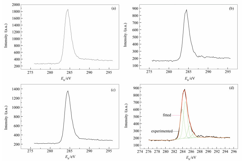
In order to gain more structure information and deposition state of coke on the surface of catalysts, the facial carbon species were studied by XPS. Figure 2 (a), 2(b), 2(c)) shows the C 1s XPS spectra of HDM 1, HDM 2 and HDM 3. Figure 2 (d) is the result of peak separation and fitting of HDM 2 by the software XPS peak. According to the reports[7, 8], the peak of (284.6±0.3) eV and (285.2±0.3) eV corresponds to C-C and graphitizing C-H, respectively. The peak of (286.0±0.3) eV correlates to C-N and (287.0±0.3) eV to C-S. The result of attribution and distribution of carbon in coke on catalysts was listed in Table 3.
Figure 2
 Figure 2. C 1s XPS and peak separation and fitting of catalysts
(a): HDM 1; (b): HDM 2; (c): HDM 3; (d): fitting of HDM 2
Table 3
Table 3. Attribution and distribution of different carbon in catalysts下载:
导出CSV
HDM 1 HDM 2 HDM 3 energy attribution AT/% energy attribution AT/% energy attribution AT/% 284.56 C-C 53.55 284.52 C-C 60.13 284.58 C-C 56.66 285.16 C-H 34.28 285.06 C-H 21.21 285.10 C-H 25.54 286.10 C-N 5.14 285.85 C-N 4.05 286.14 C-N 4.66 287.00 C-S 7.03 260.08 C-S 14.59 286.55 C-S 13.15 It can be found easily that there are normally four primary carbon species deposited on the catalysts, and their binding energy and relative area are also shown in Table 3. All the three samples share the common characteristic: C-C has the biggest relative area (content), which means the major species of coke on spent hydrotreating catalyst is graphite carbon. As for the relative content of C-N and C-S, it comes to the same conclusion with EA and TG.
2.3.2 Identification of functional groups
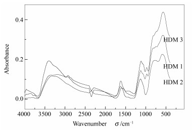
The spent catalysts were tested and analyzed by FT-IR which is shown in Figure 3.
Figure 3
The wavenumbers of each catalyst is basically the same although there is little difference in the steepness of curve. It is revealed that the organic functional groups of coke are similar but its quantity is different.
The belonging of each absorption peak, molecular vibration mode and possible structures of organic functional groups are listed in Table 4[9].
Table 4
Table 4. Functional groups of coke deposit on the spent catalysts[9]下载:
导出CSV
FT-IR peak wavenumber σ/cm-1 Functional group Mode of vibration HDM 1 HDM 2 HDM 3 577 590 571 C-S ν 744 766 740 -CH2- γ 816 810 816 R-Ar-H δ 974 1130 980 H-C=C-H δ 1124 1080 1120 C-N ν 1628 1600 1620 Ar ν 2940 2930 2930 C-H ν 3334 3360 3400 N-H ν According to the data in Table 4, the absorption peaks of alkanes C-H stretching vibration (ν) (2850-3100 cm-1)[10], aromatic ring C=C stretching vibration (1600 cm-1)[11, 12], and the peak of R-Ar-H out of plane bending vibration (δ) (810, 816 cm-1)[13]can be clearly observed. The results indicate that there is high content of aromatics in coke and unsubstituted H in the aromatic ring. The conclusion can be also gained that coke on different hydrotreating catalyst has special chemical structure but possess similar functional group.
2.3.3 Analysis of 13C NMR spectra
13C NMR is the ideal method for analyzing sophisticated structure and composition of coke without destroying its chemical structure. The structure parameters, obtained from high resolution solid state 13C NMR, can reflect the structure characteristics of coke on hydrotreating catalysts very well. Figure 4 (a) is the 13C NMR spectrogram of the three spent catalysts. It can be seen from Figure 4 that each spectrum can be classified into two main peaks: 0-70 (aliphatic carbon area) and (100-170) (aromatic carbon area).
Figure 4
In view of the low resolution of solid state 13C NMR, the spectral peaks of different functional groups should overlap and form a wide peak, and thus it is needed to unpack the overlapping peak and fit the spectrum with Origin Software. Figure 4 (b) is the result of peak separation and fitting of HDM 1. The belonging of each chemical shifts[13, 14] is listed in Table 5.
Table 5
下载:
导出CSV
Chemical shift Type Chemical shift Type 0-23 -CH3 123-129 
23-36 -CH2 36-70 -CH 129-137 
-C 137-148 Ar-C 100-123 Ar-H 148-170 Ar-X 2.4 Inference of coke structure
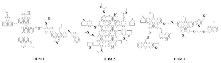
The structure parameters have been obtained by using the software Origin to analyze the 13C NMR spectrogram of spent hydrotreating catalysts. According to these parameters, the chemical structure of coke on catalyst can be inferred combining with the functional group determining by FT-IR as shown in Figure 5. It can be seen from the structures that the coke on spent hydrotreating catalyst has lower H/C and high condensation degree. HDM 2 has higher degree of condensation because it has the lowest H/C. This does agree with TG which showed HDM 2 contains less soft coke and more hard coke than others.
Figure 5
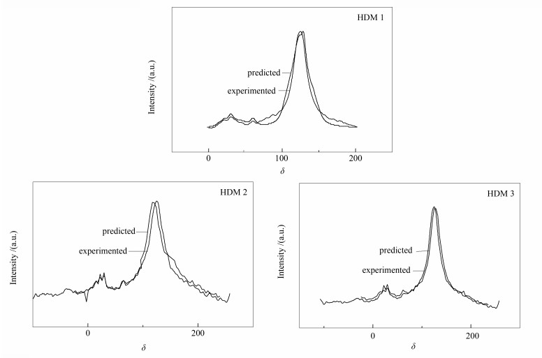
In order to conform the structure model with NMR spectra, another method was introduced to predict the 13C NMR spectra of predicted structure to compare with the experimental one and correct the simulated structure so that the simulated structure can conform to the experimental spectra very well[16-18]. The predicting spectra of simulated structure were obtained by computer software called gNMR and the results are shown in Figure 6.
Figure 6
The two curves in Figure 6 are the experimented spectra and predicted spectra. The predicted ones are obtained by leading the established structure model into software gNMR. The consistency between these two spectra show the accuracy of established structure model.
3. Conclusions
The structure parameters of coke on different spent residue hydrotreating catalysts were obtained by high resolution solid state 13C NMR. And then, the basic chemical structure model of coke were established combining with the result of EA, XPS and FT-IR. Finally, the theoretical 13C NMR spectra of the model were calculated taking the advantage of predictable software gNMR and compared with the experimental one in order to correct the model structure to match the experimental spectra.
The result showed that the main chemical structure unit of coke on spent catalysts was aromatic carbon and the aliphatic carbon only took a small part of all the carbon. Although the structure and composition of coke on spent residue hydrotreating catalysts located on different beds positions were different from each other, they still shared some common characteristics such as the kind of coke, the functional group and the structure parameters. As for the establishment of structure model, it may have profound guiding for the design and optimized project of hydrotreating catalysts.
-
-
[1]
SUN Y D, GU Z J, YANG C H. Influence of catalysts on product distribution of residue hydrotreating[J]. J Petrochem Univ, 2013, 26(30): 9-12.
-
[2]
XU C M, YANG C H. Petroleum Refining Engineering[M]. 4th ed. Beijing:Petroleum Industry Press, 2009.
-
[3]
GUO C L, FANG X C, JIA L M, LIU Q J, ZHANG X W, ZHAO X D. Investigation on coking deactivation behavior of molecular sieve catalysts[J]. Ind Catal, 2011, 19(12): 15-20.
-
[4]
XUN J K, ZHOU W, WANG J H, LI Z J, MA J X. Characterization and analysis of carbon deposited during the dry reforming of methane over No/La2O3/Al2O3 catalysts[J]. Chin J Catal, 2009, 30(11): 1076-1084. doi: 10.1016/S1872-2067(08)60139-4
-
[5]
ZHANG H C, MA B, LI J B, LIU S Q, GENG J Y, WANG J F. Analysis of coke on spent catalysts used for residue hydrotreating process[J]. Contemp Chem Ind, 2008, 37(3): 277-282.
-
[6]
WANG X. Study on structure and composition of coke on spent catalysts of commercial fixed-bed residue hydrotreating unit[D]. Qingdao: China University of Petroleum, 2014.
-
[7]
CHANG H Z, WANG C G, ZENG F G, LI J, LI W Y, XIE K C. XPS comparative analysis of coal macerals with different reducibility[J]. J Fuel Chem Technol, 2006, 34(4): 389-394.
-
[8]
MENG G, KONG D J, QI X L, XU Z Q. Carbon deposition on a toluene disproportionation and transalkylation catalyst[J]. Acta Phys-Chim Sin, 2010, 26(11): 3017-3022.
-
[9]
ZHENG Q R, ZENG F G, ZANG S T. FT-IR study on structure evolution of middle maturate coals[J]. J China Coal Soc, 2011, 36(3): 481-486.
-
[10]
ZHU N, WANG Y, CHEN F Q, ZHAN X L. Application of In situ FT-IR to deactivation by coke deposition[J]. Prog Chem, 2008, 20(10): 1447-1452.
-
[11]
YANG X, TIAN H P, WANG S H. Characterization of coke on spent catalytic cracking catalysts by integrated techniques[J]. Acta Pet Sin (Pet Proc Sect), 2011, 27(2): 198-206.
-
[12]
SUN Q L, LI W, LI D T, CHEN H K, LI B Q, BAI X F, LI W H. Relationship between structure characteristics and thermal conversion property of Shenmu maceral concentrates[J]. J Fuel Chem Technol, 2003, 31(2): 97-102.
-
[13]
HE Y G, HE Y F. Characterization of coke precursor deposited on the surface of solid acid alkylation catalysts[J]. Chin J Catal, 2000, 21(2): 175-178.
-
[14]
ANDRE H, ANTHONY S, ABDULAZEM M, AWATERF A. Initial coke deposition on hydrotreating catalysts. PartⅡ. Structure elucidation of initial coke on hydrodematallation catalysts[J]. Fuel, 2005, 84(2/3): 259-269.
-
[15]
MEI Y F, ZHAO X, SUN W F, TANG J, QIAO A X. Spectral analysis of coal tar from Xiaohuangshan region[J]. Chin J Magn Reson, 2011, 28(3): 339-348.
-
[16]
XIANG J H, ZENG F G, LI B, ZHANG L, LI M F, LIANG H Z. Construction of macromolecular structural model of anthracite from Chengzhuang coal mine and its molecular simulation[J]. J Fuel Chem Technol, 2013, 41(4): 391-399. doi: 10.1016/S1872-5813(13)60022-5
-
[17]
JIA J B, ZENG F G, SUN B L. Construction and modification of macromolecular structure model for vitrinite from Shendong 2-2 coal[J]. J Fuel Chem Technol, 2011, 39(9): 652-657.
-
[18]
XIANG J H, ZENG F G, LIANG H Z, SUN B L, ZHANG L, LI M F, JIA J B. Model construction of the macromolecular structure of Yanzhou coal and its molecular simulation[J]. J Fuel Chem Technol, 2011, 39(7): 481-488. doi: 10.1016/S1872-5813(11)60031-5
-
[1]
-
Figure 2 C 1s XPS and peak separation and fitting of catalysts
(a): HDM 1; (b): HDM 2; (c): HDM 3; (d): fitting of HDM 2
Table 1. Basic information of catalysts
Catalyst No. Reactor No. Catalyst species Sampling location in bed HDM 1 1 Ch-B top HDM 2 1 Ch-B middle HDM 3 1 Ch-B bottom  下载: 导出CSV
Table 2. Elemental contents of spent catalysts
No. Catalyst species Content w/% nH/nC H C N S HDM 1 Ch-B 0.89 10.40 0.21 1.66 1.02 HDM 2 Ch-B 1.39 19.42 0.35 6.73 0.85 HDM 3 Ch-B 1.04 10.05 0.20 2.95 1.23
下载: 导出CSV
Table 3. Attribution and distribution of different carbon in catalysts
HDM 1 HDM 2 HDM 3 energy attribution AT/% energy attribution AT/% energy attribution AT/% 284.56 C-C 53.55 284.52 C-C 60.13 284.58 C-C 56.66 285.16 C-H 34.28 285.06 C-H 21.21 285.10 C-H 25.54 286.10 C-N 5.14 285.85 C-N 4.05 286.14 C-N 4.66 287.00 C-S 7.03 260.08 C-S 14.59 286.55 C-S 13.15
下载: 导出CSV
Table 4. Functional groups of coke deposit on the spent catalysts[9]
FT-IR peak wavenumber σ/cm-1 Functional group Mode of vibration HDM 1 HDM 2 HDM 3 577 590 571 C-S ν 744 766 740 -CH2- γ 816 810 816 R-Ar-H δ 974 1130 980 H-C=C-H δ 1124 1080 1120 C-N ν 1628 1600 1620 Ar ν 2940 2930 2930 C-H ν 3334 3360 3400 N-H ν
下载: 导出CSV
-


 扫一扫看文章
计量
- PDF下载量: 0
- 文章访问数: 0
- HTML全文浏览量: 0
 下载:
下载:
