
图 1
The molecular structure of IIDDT-C3.
Figure 1.
The molecular structure of IIDDT-C3.
To improve alignment of isoindigo-based conjugated polymer film by controlling contact line receding velocity
Shuai-Jie Chi , Liang Chen , Hong-Xiang Li , Jian-Gang Liu , Xin-Hong Yu , Yan-Chun Han

D-A conjugated polymers have gained extensive attention and have been widely used in organic solar cells, field effect transistors, because of their excellent electronic properties [1-9]. The device performance has a close relationship with the molecular structure, processing method and film morphology [10-12], so it is of great significance to study the relationship between the above mentioned factors. Plenty of researches have revealed that charge carrier mobility can be enhanced remarkably by aligning the molecules and crystals [13-16].
There have been efforts to align conjugated polymers by introducing external force [17-21]. Yang et al. attained highly aligned P3HT film through rubbing at 150 ℃ after spin-coating [22]. Bao et al. described the growth of a highly aligned meta-stable structure of C8-BTBT by off-center spin-coating, which provided significantly increased charge carrier mobility up to 43 cm2/V/s [19]. Takeya et al. spread PB16TTT polymer films on the surface of an ionic liquid and then compressed the films mechanically to align the polymer chains [23]. The aligned polymer film could also be prepared by molecular interactions [24-28]. Samitsu et al. investigated the molecular arrangement of PQT12 in a nematic liquid crystal E44 and found that PQT12 exhibited preferential alignment parallel to the nematic direction [29]. F8T2, which possessed liquid crystalline property, could also obtained well aligned film [28]. Brinkmann et al. reported evidence for the semicrystalline structure of P3HT that has been oriented by directional solidification on 1, 3, 5-trichlorobenzene [30]. Aligned polymer film could also be prepared by controlling the contact line receding velocity, such as zone-casting [31-33], dip-coating [34, 35], flow-coating [36, 37], solution-shearing [37-40] and so on. Giri et al. obtained film with high alignment degree of TIPSpentacene through adjusting the contact line receding velocity and the temperature gradient by solution-shearing [37].
D-A conjugated polymers, isoindigo-based conjugated polymers exhibit excellent electronic performance [41-46]. Jian Pei et al. synthesized conjugated polymer IIDDT, which based on an isoindigo core, and developed for organic field-effect transistors by spin-coating. Investigation of their field effect performance indicated that IIDDT exhibited air-stable mobility up to 0.79 cm2/V/s, which is quite high among polymer FET materials. Changduk Yang et al. presented an easily synthesized D-A semiconducting polymer based on alternating thienoisoindigo (TIIG) and simple naphthalene (Np) units, PTIIG-Np. PTIIG-Np offered favorable property of charge-carrier mobility (up to 5.8 cm2/V/s) because of its inherently large co-planarity, favorable energetic levels for hole injection, as well as its closer π-π stacking distance. However, the fibers mentioned in these works arranged in a random manner, implying that there were large amounts of grain boundaries, which inhibited the further improvement of charge carrier mobility. According to the viewpoint of R. A. Street [13], the grain boundaries between crystallites limit conduction of charge carriers. Long range orientation of backbones could improve charge carrier mobility remarkably through reducing the energy barriers of grain boundaries between adjacent crystals.
In this paper, we prepared aligned IIDDT-C3 polymer film by drop-casting under solvent vapor environment at high temperature. We controlled the contact line receding velocity through adjusting solvent vapor content and film-formation temperature. We found that the film attained the highest degree of alignment when the contact line receding velocity was in accordance with the critical alignment velocity.
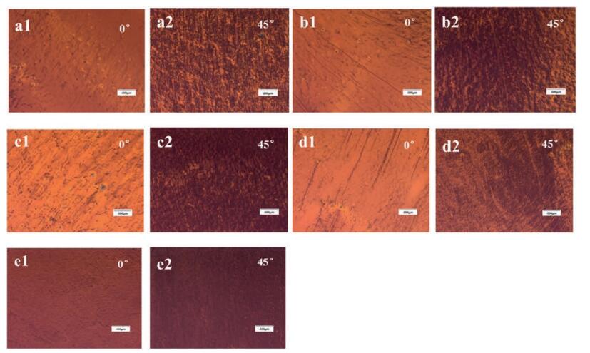
We characterized the macro anisotropy of IIDDT-C3 (Fig. 1) films by optic microscopy at 100 fold magnification in the polarized light mode (Fig. 2). When the content of solvent vapor was 0 mL, the optic macro scope image of IIDDT-C3 films obtained at 0° with respect to crossed polarizer and analyzer showed similar brightness in contrast to image obtained at 45°, which indicated the weak alignment of IIDDT-C3 film. When the content of solvent vapor was increased, the difference of the brightness between the images obtained at 0° and 45° became more obvious. When the content of solvent vapor was 0.3 mL, the optic macro scope images of IIDDT-C3 films obtained at 0° with respect to crossed polarizer and analyzer displayed large areas of bright zones in contrast to the dark images obtained at 45°, which indicated that IIDDT-C3 films had more significant apparent optic anisotropy in macro scales. When the content of solvent vapor was continued to increase, the contrast between the bright zones and dark zones became less obvious, which indicated the reduction of macro alignment degree of IIDDT-C3 films. When the content of solvent vapor increased up to 1.0 mL, the macro alignment degree of IIDDT-C3 films reduced to minimum.
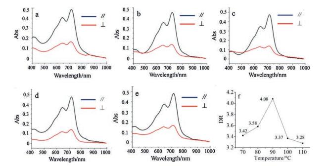
To further study the alignment of IIDDT-C3 films quantitatively, we characterized the dichroic ratio (Fig. 3). When the content of solvent vapor increased from 0 mL to 0.3 mL, the dichroic ratio of IIDDT-C3 films was improved from 2.12 to 3.42. However, when the content of solvent vapor was increased from 0.3 mL to 1.0 mL, the dichroic ratio of IIDDT-C3 films was reduced from 3.42 to 2.57. This demonstrated that with the increasing of the content of solvent vapor, the alignment degree of IIDDT-C3 films was first improved and then reduced.

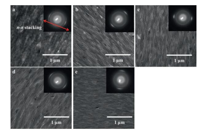
Then we characterized the micro morphology of IIDDT-C3 films through TEM. In Fig. 4, it was found that when the content of solvent vapor increased from 0 mL to 0.3 mL, the fiber structure with good alignment was formed in the IIDDT-C3 films, gradually. When the content of solvent vapor was 0.3 mL, the IIDDT-C3 film obtained the highest degree of alignment since the diffraction rings of the p-p stacking (3.63 Å) was became the sharpest. As the content of solvent vapor was continued to increase, the alignment degree of IIDDT-C3 films became lower, and the breadth of diffraction rings was became wider, which was in accordance with the optic macro scope images in Fig. 2. Long-range ordered morphology could not only decrease the amount of grain boundary, but also induce better planarization of tie-molecules between different crystalline regions, which was beneficial for the improvement of charge carrier mobility.
In Fig. 5, it was found that when the content of solvent vapor was increased from 0 mL to 1.0 mL, the intensity of diffraction peak was improved gradually, which indicated the enhancement of the crystallinity of IIDDT-C3. This was because the films of IIDDT-C3 had more sufficient time to self-assemble as the content of solvent vapor was increased from 0 mL to 1.0 mL. In addition, according to Bragg equation,

|
|
where d is the lattice spacing, θ is the scattering angle and λ is the wavelength of X-ray, it was calculated that the peaks in XRD profiles with a d-spacing of 24.58 Å was correspond to the alkylstacking (100) of IIDDT-C3. Through the TEM morphology images and relevant diffraction images, it was found that the backbone of IIDDT-C3 molecules was arranged parallel with the growth direction of fibers and adopted an edge-on orientation.
From the above mentioned experiments we could draw the conclusion that when the content of solvent vapor was 0.3 mL, the highest degree of alignment was attained in the IIDDT-C3 film. To further improve the alignment degree of IIDDT-C3, we optimized the film formation temperature. The films were prepared by dropcasting at different temperatures under the condition of the content of solvent vapor was 0.3 mL. All the weighing bottles were covered until the solvent was dried up.
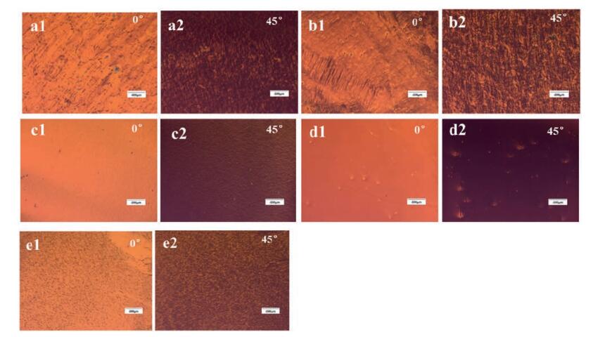
We first characterized the macro anisotropy of IIDDT-C3 films by optic microscopy at 100 fold in the polarized light mode (Fig. 6). When the film-formation temperature was increased from 70 ℃ to 90 ℃, the optic macro scope image of IIDDT-C3 films obtained at 0° with respect to crossed polarizer and analyzer showed more obviously bright and dark change in contrast to images obtained at 45°, which indicated the higher alignment degree of IIDDT-C3 film. When the film-formation temperature was continued to increase to 110 ℃, the contrast of brightness between the images obtained at 0° and 45° became less obvious, which indicated the reduction of optic anisotropy in macro scales.
To further study the alignment of IIDDT-C3 films quantitatively, we characterized the dichroic ratio (Fig. 7). When the filmformation temperature was increased from 70 ℃ to 90 ℃, the dichroic ratio of IIDDT-C3 films was improved from 3.42 to 4.08. When the film-formation temperature was continued to increase from 90 ℃ to 110 ℃, the dichroic ratio of IIDDT-C3 films was reduced to 3.28. This demonstrated that with the increasing of the film-formation temperature, the alignment degree of IIDDT-C3 films was first improved and then reduced.
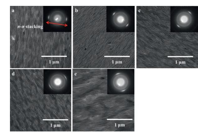
Then we characterized the micro morphology of IIDDT-C3 films through TEM. In Fig. 8, it was found that when the film-formation temperature was increased from 70 ℃ to 90 ℃, the fiber structure with better alignment was formed and the diffraction rings were sharper in the IIDDT-C3 films. As the film-formation temperature was continued to increase, the alignment degree of IIDDT-C3 films became lower, and the breadth of diffraction rings became wider, which was in accordance with the optic macro scope images in Fig. 6.
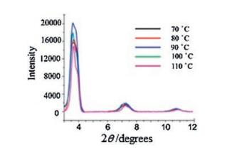
In Fig. 9, it was found that when the film-formation temperature was increased from 70 ℃ to 90 ℃, the intensity of diffraction peak was improved gradually, which indicated the enhancement of the crystallinity of IIDDT-C3. While as the filmformation temperature was continued to increase to 110 ℃, the intensity of diffraction peak became weaker, this indicated the reduction of the crystallinity of IIDDT-C3. In addition, according to Bragg equation, it was calculated that the peaks in XRD profiles with a d-spacing of 24.58 Å was correspond to the alkyl-stacking (100) of IIDDT-C3. The IIDDT-C3 molecules adopted an edge-on orientation.
According to the Rogowski's theory [47],
|
|
where Uth is the critical alignment velocity, Qev is the solvent evaporation flux, σ is the solution surface energy, ρ is the solution density, and η is the solution viscosity, the alignment degree of polymer film was related to the contact line receding velocity and the critical alignment velocity. When the receding velocity of contact line was in accordance with the critical alignment velocity, the highest degree of alignment could be attained in the polymer film.
By adjusting the content of solvent vapor during the filmformation process, it was found that when the content of solvent vapor was 0 mL, the alignment degree was low. As the content of solvent vapor was increased to 0.3mL, the highest degree of alignment was attained in the IIDDT-C3 film. While as the content of solvent vapor was continued to increase to 1.0mL, the alignment degree was reduced again.
We analyzed that when the content of solvent vapor was 0mL, thesolventin the solution was evaporated quickly and thereceding velocity of contact line was fast. The molecules of IIDDT-C3 could not be self-assembled sufficiently, and this lead to the reduction of crystallinity and alignment. As the content of solvent vapor was increased, the contact line receding velocity became slower. There was more time for the molecules of IIDDT-C3 to self-assemble and the crystallization degree was improved. When the content of solvent vapor was 0.3mL, the receding velocity of contact line was in accordance with the critical alignment velocity and the highest degree of alignment was attained in the IIDDT-C3 film. When the content of solvent vapor was continued to increase, the receding velocity of contact line was slower, the film-formation time became longer, and the alignment degree was reduced again. This was because the receding velocity of contact line was slower than the critical alignment velocity. When the receding velocity of contact line was too slow, the molecules of IIDDT-C3 were transferred from kinetics equilibrium to thermodynamics equilibrium which was more stable in energy. As a result, the anisotropy of the solution-shearing during the contact line receding was weaken and the degree of alignment was reduced.
Besides, it was found that the crystallization degree was improved with the increase of solvent vapor content. This was because with increasing the film-formation time, there was more time for the molecules of IIDDT-C3 to self-assemble, and this led to the improvement of crystallization degree. This was not contradictory to the phenomenon that the alignment degree was improved first and then reduced as the content of solvent vapor increased. The improvement of alignment degree was because of the match between the contact line receding velocity and the critical alignment velocity. Fibers were aligned parallel with the direction of the contact line receding. While when the film formation time was prolonged, the molecules were transformed to thermodynamics equilibrium which was more stable in energy and were isotropic. As a result, the alignment degree was reduced. However, this did not mean the reduction of crystallization degree inevitably.
By adjusting the film formation temperature, we found that the highest degree of alignment was attained in the IIDDT-C3 film when the film-formation temperature was 90 ℃. With the increasing the temperature, the alignment degree was reduced. We attributed this phenomenon to the variation of contact line receding velocity.
As the film formation temperature was increased from 70 ℃ to 90 ℃, the solvent was evaporated more quickly, and the critical alignment velocity became faster. As a result, the contact line receding velocity was still in accordance with the critical alignment velocity, and IIDDT-C3 film attained higher alignment degree. When the temperature was continued to increase to 110 ℃, owing to the exceedingly fast contact line receding velocity, the molecules of IIDDT-C3 could not be aligned sufficiently.
In this work, we studied the relationship between the alignment degree and the contact line receding velocity. When the solvent vapor content was too little or the film formation temperature was too high, the solvent was evaporated too quickly and there was not enough time for IIDDT-C3 molecules to selfassemble, which was detrimental to improve the alignment degree. While when there was too much solvent vapor or the film formation temperature was too low, the contact line receding velocity was too slow, the aligned molecules of IIDDT-C3 sheared by the contact line receding were transferred from kinetics equilibrium to thermodynamics equilibrium, which was more stable in energy, and the alignment degree was reduced. Only when solvent vapor content was 0.3 mL and the film-formation temperature was 90 ℃, the contact line receding velocity was in accordance with the critical alignment velocity, and the highest degree of alignment was attained in the IIDDT-C3 film, with the dichroic ratio up to 4.08.
The copolymer of isoindigo and bithiophene (IIDDT-C3) was purchased from 1-Material Inc. Fig. 1 shows the molecular structure of IIDDT-C3. The molecular weight (Mn) and polydispersity index (PDI) were 26 kDa and 2.66. Chlorobenzene(CB) was purchased from Sinopharm Chemical Reagent Co., Ltd. The glass slides as substrates were cleaned in piranha solution (70/30 v/v of concentrated H2SO4 and 30% H2O2) at 90 ℃ for 30 min and then treated with deionized water by ultrasound. Finally the glass slides were blown dry by nitrogen.
IIDDT-C3 was dissolved by CB at a concentration of 0.5 mg/mL. The solution was heated at 70 ℃ to be fully dissolved. All film samples were prepared by drop-casting the IIDDT-C3/CB solution at high temperature under the condition of solvent vapor enhancement with 50 μL in each glass slide.
For the preparation of the first part of samples, we placed glass slides into the weighing bottles with CB of 0 mL, 0.1 mL, 0.3 mL, 0.5 mL, 1.0 mL, respectively. Then the weighing bottles were sealed at 70 ℃ until the solvent was dried.
While for the preparation of the second part of the samples, we placed glass slides into weighing bottles with CB of 0.3 mL. Then the weighing bottles were sealed until the solvent dried at the temperature of 70 ℃, 80 ℃, 90 ℃, 100 ℃, 110 ℃, respectively.
The macroscopic morphology of IIDDT-C3 films were charac terized by Karl-Zeiss optic microscopy in the polarized light mode.
Transmission electron microscopy (TEM) images and selected area electron diffraction patterns (SAED) were obtained with a JEOL JEM-1011 transmission electron microscope (Japan). The accelerating voltage was 100 kV.
Dichroic ratio was characterized by an AvaSpect-3648 optical fiber spectrometer (Netherlands) equipped with a polarizer. The anisotropy was defined as the dichroic ratio between max absorption parallel and perpendicular to polarization direction.
GIXRD pattern was obtained on Bruker D8 Discover Reflector (Cu Kα, λ = 1.54056 Å) under 40 kV and 40 mA tube current.
This work was supported by the National Natural Science Foundation of China (Nos. 21334006, 51573185, 21474113), the Strategic Priority Research Program of the Chinese Academy of Sciences (No. XDB12020300) and OTFT National Key R & D Program of "Strategic Advanced Electronic Materials" (No. 2016YFB0401100).
Sirringhaus H.. 25th Anniversary article:organic field-effect transistors:the path beyond amorphous silicon[J]. Adv. Mater., 2014, 26: 1319-1335. doi: 10.1002/adma.201304346
Olivier Y., Niedzialek D., Lemaur V.. 25th anniversary article:highmobility hole and electron transport conjugated polymers:how structure defines function[J]. Adv. Mater., 2014, 26: 2119-2136. doi: 10.1002/adma.v26.14
Dutta G.K., Han A.R., Lee J.. Visible-near infrared absorbing polymers containing thienoisoindigo and electron-rich units for organic transistors with tunable polarity[J]. Adv. Funct. Mater., 2013, 23: 5317-5325. doi: 10.1002/adfm.v23.42
Li Y., Li M., Su Y.. et al, Liquid crystal character controlled by complementary discotic molecules mixtures:columnar stacking type and mesophase temperature range[J]. Chin. Chem. Lett., 2016, 27: 475-480. doi: 10.1016/j.cclet.2015.12.024
Gao X., Liu J., Sun Y., Xing R., Han Y.. Effects of aggregation of poly(3-hexylthiophene) in solution on uniaxial alignment of nanofibers during zone casting[J]. Chin. Chem. Lett., 2013, 24: 23-27. doi: 10.1016/j.cclet.2013.01.014
Gao X., Han Y.. P3HT stripe structure with oriented nanofibrils enabled by controlled inclining evaporation[J]. Chin. J. Polym. Sci., 2013, 31: 610-619. doi: 10.1007/s10118-013-1259-y
Gao X., Xing R., Liu J., Han Y.. Uniaxial alignment of poly(3-hexylthiophene) nanofibers by zone-casting approach[J]. Chin. J. Polym. Sci., 2013, 31: 748-759. doi: 10.1007/s10118-013-1284-x
Sun Y., Liu J., Ding Y., Han Y.. Controlling the surface composition of PCBM in P3HT/PCBM blend films by using mixed solvents with different evaporation rates[J]. Chin. J. Polym. Sci., 2013, 31: 1029-1037. doi: 10.1007/s10118-013-1295-7
Chi S., Chen L., Liu J.. Influence of bifurcation position and length of side chains on the structure of isoindigo-based conjugated polymer thin films[J]. Chin. Chem. Lett., 2017, 28: 333-337. doi: 10.1016/j.cclet.2016.09.005
Guo X., Facchetti A., Marks T.J.. Imide-and amide-functionalized polymer semiconductors[J]. Chem. Rev., 2014, 14: 8943-9021.
Pearson A.J., Wang T., Dunbar A.D.F.. Morphology development in amorphous polymer:fullerene photovoltaic blend films during solution casting[J]. Adv. Funct. Mater., 2014, 24: 659-667. doi: 10.1002/adfm.201301922
Li Y., Li H., Chen H.. Controlling crystallite orientation of diketopyrrolopyrrole-based small molecules in thin films for highly reproducible multilevel memor[J]. Adv. Funct. Mater., 2015, 25: 4246-4254. doi: 10.1002/adfm.v25.27
Street R.A.. Unraveling charge transport in conjugated polymers[J]. Science, 2013, 341: 1072-1073. doi: 10.1126/science.1242935
Noriega R., Rivnay J., Vandewal K.. A general relationship between disorder, aggregation and charge transport in conjugated polymers[J]. Nat. Mater., 2013, 12: 1038-1044. doi: 10.1038/nmat3722
Zhang X., Bronstein H., Kronemeijer A.J.. Molecular origin of high fieldeffect mobility in an indacenodithiophene-benzothiadiazole copolymer[J]. Nat. Commun, 2013, 4: 2238.
Takacs C.J., Treat N.D., Kramer S.. Remarkable order of a highperformance polymer[J]. Nano Lett., 2013, 13: 2522-2527. doi: 10.1021/nl4005805
Song P., Li Y., Ma F.. Insight into external electric field dependent photoinduced intermolecular charge transport in BHJ solar cell materials[J]. J. Mater. Chem. C, 2015, 3: 4810-4819. doi: 10.1039/C5TC00920K
Wang H., Chen L., Xing R.. Simultaneous control over both molecular order and long-range alignment in films of the donor-acceptor copolymer[J]. Langmuir, 2015, 31: 469-479. doi: 10.1021/la5037772
Yuan Y., Giri G., Ayzner A.L.. Ultra-high mobility transparent organic thin film transistors grown by an off-centre spin-coating method[J]. Nat. Commun, 2014, 5: 3005.
Amundson, B.J.Sapjeta, A.J.Lovinger. An in-plane anisotropic organic semiconductor based upon poly(3-hexyl thiophene)[J]. Thin Solid Films, 2002, 414: 143-149. doi: 10.1016/S0040-6090(02)00338-3
Derue G., Serban D.A., Lecl P., re è. Controlled nanorubbing of polythiophene thin films for field-effect transistors[J]. Org. Electron., 2008, 9: 821-828. doi: 10.1016/j.orgel.2008.05.024
Zhu R., Kumar A., Yang Y.. Polarizing organic photovoltaics[J]. Adv. Mater., 2011, 23: 4193-4198. doi: 10.1002/adma.201101514
Soeda J., Matsui H., Okamoto T.. Highly oriented polymer semiconductor films compressed at the surface of ionic liquids for high-performance polymeric organic field-effect transistors[J]. Adv. Mater., 2014, 26: 6430-6435. doi: 10.1002/adma.201401495
Tseng H.R., Phan H., Luo C.. High-mobility field-effect transistors fabricated with macroscopic aligned semiconducting polymers[J]. Adv. Mater., 2014, 26: 2993-2998. doi: 10.1002/adma.201305084
Kim D.H., Jang Y., Park Y.D.. Surface-induced conformational changes in poly(3-hexylthiophene) monolayer films[J]. Langmuir, 2005, 21: 3203-3206. doi: 10.1021/la047061l
Skrypnychuk V., Boulanger N., Yu V.. Enhanced vertical charge transport in a semiconducting P3HT thin film on single layer graphene[J]. Adv. Funct. Mater., 2015, 25: 664-670. doi: 10.1002/adfm.201403418
Lin C., Liub C.-L., Chen W.. Poly(3-hexylthiophene)/graphene composites based aligned nanofibers forhigh performance field effect transistors[J]. J. Mater. Chem. C, 2015, 3: 4290-4296. doi: 10.1039/C5TC00399G
Sirringhaus H., Wilson R.J., Friend R.H.. Mobility enhancement in conjugated polymer field-effect transistors through chain alignment in a liquid-crystalline phase[J]. Appl. Phys. Lett., 2000, 77: 406-408. doi: 10.1063/1.126991
Samitsu S., Takanishi Y., Yamamoto J.. Self-assembly and one-dimensional alignment of a conducting polymer nanofiber in a nematic liquid crystal[J]. Macromolecules, 2009, 42: 4366-4368. doi: 10.1021/ma900826h
Brinkmann M., Wittmann J.C.. Orientation of regioregular poly(3-hexylthiophene) by directional solidification:a simple method to reveal the semicrystalline structure of a conjugated polymer[J]. Adv. Mater., 2006, 18: 860-863. doi: 10.1002/(ISSN)1521-4095
Anokhin D.V., Rosenthal M., Makowski T.. Comparative structural study of thin films of a columnar liquid crystal aligned by mechanical shearing and zone casting[J]. Thin Solid Films, 2008, 17: 982-985.
Wade J., Steiner F., Niedzialek D.. Charge mobility anisotropy of functionalized pentacenes in organic field effect transistors fabricated by solution processing[J]. J. Mater. Chem. C, 2014, 2: 10110-10115. doi: 10.1039/C4TC01353K
Pisula W., Menon A., Stepputat M.. A zone-casting technique for device fabrication of field-effect transistors based on discotic hexa-peri hexabenzocoronene[J]. Adv. Mater., 2005, 17: 684-689. doi: 10.1002/adma.200401171
Xue L., Gao X., Zhao K.. The formation of different structures of poly(3-hexylthiophene) film on a patterned substrate by dip coating from aged solution[J]. Nanotechnology, 2010, 21: 145303. doi: 10.1088/0957-4484/21/14/145303
Wang S., Kiersnowski A., Pisula W.. Microstructure evolution and device performance in solution-processed polymeric field-effect transistors:the key role of the first monolayer[J]. J. Am. Chem. Soc., 2012, 134: 4015-4018. doi: 10.1021/ja211630w
DeLongchamp D.M., Kline R.J., Jung Y.. Controlling the orientation of terraced nanoscale ribbons of a poly(thiophene) semiconductor[J]. ACS Nano, 2009, 3: 780-787. doi: 10.1021/nn800574f
Giri G., Verploegen E., Mannsfeld S.C.. Tuning charge transport in solution-sheared organic semiconductors using lattice strain[J]. Nature, 2011, 480: 504-508. doi: 10.1038/nature10683
Diao Y., Tee B.C.-K., Giri G.. Solution coating of large-area organic semiconductor thin films with aligned single-crystalline domains[J]. Nat. Mater., 2013, 12: 665-671. doi: 10.1038/nmat3650
Giri G., DeLongchamp D.M., Reinspach J.. Effect of solution shearing method on packing and disorder of organic semiconductor polymers[J]. Chem. Mater., 2015, 27: 2350-2359. doi: 10.1021/cm503780u
Shin J., Hong T.R., Lee T.W.. Template-guided solution-shearing method for enhanced charge carrier mobility in diketopyrrolopyrrole-based polymer field-effect transistors[J]. Adv. Mater., 2014, 26: 6031-6035. doi: 10.1002/adma.201401179
Lei T., Cao Y., Fan Y.. High-performance air-stable organic field-effect transistors:isoindigo-based conjugatedpolymers[J]. J. Am. Chem. Soc., 2011, 133: 6099-6101. doi: 10.1021/ja111066r
Mei J., Kim do H., Ayzner A.L.. Siloxane-terminated solubilizing side chains:bringing conjugated polymer backbones closer and boosting hole mobilities in thin-film transistors[J]. J. Am. Chem. Soc., 2011, 133: 20130-20133. doi: 10.1021/ja209328m
Lei T., Dou J.H., Ma Z.J.. Siloxane-terminated solubilizing side chains:bringing conjugated polymer backbones closer and boosting hole mobilities in thin-film transistors[J]. J. Am. Chem. Soc., 2012, 134: 20025-20028. doi: 10.1021/ja310283f
Glowacki E.D., Voss G., Sariciftci N.S.. 25th Anniversary article:progress in chemistry and applications of functional indigos for organic electronics[J]. Adv. Mater., 2013, 25: 6783-6800. doi: 10.1002/adma.v25.47
Lei T., Dou J.H., Cao X.Y.. A BDOPV-based donor-acceptor polymer for high-performance n-type and oxygen-doped ambipolar field-effect transistors[J]. Adv. Mater., 2013, 25: 6589-6593. doi: 10.1002/adma.201302278
Kim G., Kang S.J., Dutta G.K.. A thienoisoindigo-naphthalene polymer with ultrahigh mobility of 14.4cm2/Vs that substantially exceeds benchmark values for amorphous silicon semiconductors[J]. J. Am. Chem. Soc, 2014, 136: 9477-9483. doi: 10.1021/ja504537v
Rogowski R.Z., Darhuber A.A.. Crystal growth near moving contact lines on homogeneous and chemically patterned surfaces[J]. Langmuir, 2010, 26: 11485-11493. doi: 10.1021/la101002x

Figure 2 Optic microscope images in polarized light mode of IIDDT-C3 films prepared by drop-casting at 70 ℃ under the following conditions: (a) SVE = 0 mL (b) SVE = 0.1 mL (c) SVE = 0.3 mL (d) SVE = 0.5 mL (e) SVE = 1.0 mL.

Figure 3 UV-vis absorption spectra of IIDDT-C3 films with radial direction parallel and perpendicular to polarized direction. The films were prepared by drop-casting at 70 ℃ under the following conditions: (a) SVE = 0 mL (b) SVE = 0.1 mL (c) SVE = 0.3 mL (d) SVE = 0.5 mL (e) SVE = 1.0 mL. (f) The variation of dichroic ratio of IIDDT-C3 films prepared under different SVE conditions.

Figure 4 The TEM images of IIDDT-C3 films prepared by drop-casting at 70 ℃ under the following conditions: (a) SVE = 0 mL (b) SVE = 0.1 mL (c) SVE = 0.3 mL (d) SVE = 0.5 mL (e) SVE = 1.0 mL. The red arrow in electron diffraction patterns represents π-π stacking directions.

Figure 5 The XRD profile of IIDDT-C3 films prepared by drop-casting at 70 ℃ under different SVE conditions.

Figure 6 Optic microscope images in polarized light mode of IIDDT-C3 films prepared by drop-casting under the condition of SVE = 0.3 mL at the following temperatures: (a) 70 ℃ (b) 80 ℃ (c) 90 ℃ (d) 100 ℃ (e) 110 ℃.

Figure 7 UV-vis absorption spectra of IIDDT-C3 films with radial directionparallel and perpendicular to polarized direction. The films were prepared by drop-casting under the condition of SVE=0.3mL at the following temperatures: (a) 70 ℃ (b) 80 ℃ (c) 90 ℃ (d) 100 ℃ (e) 110 ℃. (f) The variation of dichroic ratioof IIDDT-C3 films prepared under the condition of SVE=0.3mL at different temperatures.

Figure 8 The TEM images of IIDDT-C3 films prepared by drop-casting under the condition of SVE=0.3mL at the following temperatures (a) 70 ℃ (b) 80 ℃ (c) 90 ℃ (d) 100 ℃ (e) 110 ℃.

 扫一扫看文章

扫一扫关注我们
 下载:
下载:


 下载:
下载:

 下载:
下载: