Figure 1.
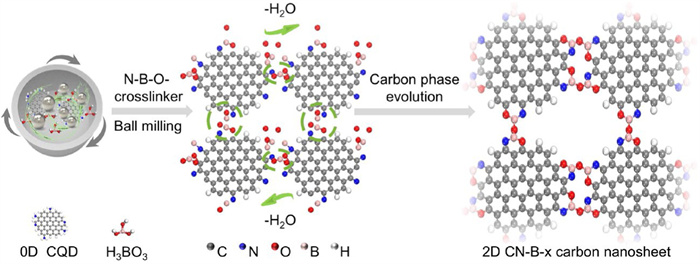
Schematic diagram of synthesis of 0D N-CQD to 2D CN-B-x carbon nanosheets.
N-B-O-crosslinker-induced mechanochemical conversion of carbon phase unlocks efficient hydrogen peroxide electrosynthesis
Leping Xie , Caihong Liang , Huazhang Guo , Kang Wang , Shihao Zhang , Jiye Zhang , Yeng Ming Lam , Zheng Liu , Liang Wang

Hydrogen peroxide (H2O2) is an important oxidizing agent extensively utilized in organic synthesis [1], disinfection, and bleaching, due to its high oxidizing capability and environmentally benign byproduct (water). The current industrial production of H2O2 predominantly uses the anthraquinone process, which relies on costly precious metal catalysts and toxic organic solvents, coupled with complex operational requirements that hinder scalability [2]. As an alternative, the two-electron (2e-) oxygen reduction reaction (ORR) offers a promising route for H2O2 synthesis, characterized by its mild conditions, safety, cost-effectiveness, and efficiency [3,4]. The exploration of efficient and cost-effective electrocatalysts is the key to facilitating this 2e- ORR process, presenting significant opportunities for future research.
Metal-free carbon materials have attracted considerable attention as pivotal candidates in electrochemical H2O2 synthesis due to their low cost, exceptional conductivity, large specific surface area, and superior stability [5,6]. Heteroatom doping, particularly with nitrogen-boron (N–B) bonds, can significantly influence the physical and electronic properties of carbon materials. N–B bonds, formed via sp2 hybridization, create a coplanar conjugated skeleton that enhances molecular packing and charge transport [7]. However, most B, N co-doped carbon materials preferentially promote the 4e- pathway over the 2e- pathway. Beyond various traditional carbon nanomaterials, zero-dimensional (0D) carbon quantum dot (CQD) serve as an alternative, offering precise regulation of functional groups. Especially, our recent work demonstrated that N–B–O site-activated graphene quantum dots exhibit high catalytic activity for the 2e- ORR, underscoring the synergistic effects of B and N co-doping on metal-free carbon electrocatalysts [8].
In this study, we fabricated nitrogen-rich CQD through a hydrothermal reaction [9,10], followed by high-speed mechanical ball milling with boric acid to form crosslinker, converting 0D CQD into two-dimensional (2D) carbon nanosheets. Experimental results revealed that increasing N–B–O bond content enhanced the size and thickness of the carbon nanosheets, improving their electrochemical performance for H2O2 generation. The prepared CN-B-3 demonstrates the highest H2O2 selectivity (over 98%) and stability, accompanied by a significantly increased ring current density (0.4 V vs. RHE, 0.46 mA/cm2). Such optimal sample was further evaluated in a flow cell setup. The H2O2 production yield (213 mmol/L) signifies the strong potential of the CN-B-3 for portable application. Through evaluating electrocatalytic performance, the relationship between N–B–O– bond formation and the conversion of 0D CQD to 2D carbon nanosheets, and their impact on ORR and H2O2 production were elucidated. In-situ technology and theoretical calculations further unraveled that mixing with boric acid promotes the integration of N-CQD into stable carbon nanosheets by forming crosslinker containing boron, oxygen, nitrogen and carbon atoms at edges of CQD. Our work provides a new perspective for the synthesis of 2D nanosheet materials for efficient ORR to produce H2O2.
Fig. 1 presents a schematic illustration of fabricating of N-CQD to CN-B-x carbon nanosheets structure, showcasing a progression from 0D to 2D dimensions, where periodic structure is regulated to achieve large sizes. Originally, N-CQD was synthesized and subsequently subjected to high-speed mechanical ball milling with boric acid [11], leading to the transformation of N-CQD towards carbon nanosheets (CN-B-x, x means the addition mass of boric acid). With the increase of the ratio of N-CQDs to boric acid dosage, the preparation for the process from 0D materials to 2D nanosheets has been achieved. Our hypothesis posits the incorporation of boric acid within the N-CQD matrix could facilitate the formation of N–B–O– crosslinker configurations, with a process accompanied by dehydration. This dehydration-induced mechanism not only elucidates the structural evolution from 0D to 2D, but also underscores the pivotal role of boric acid in the transformation process.
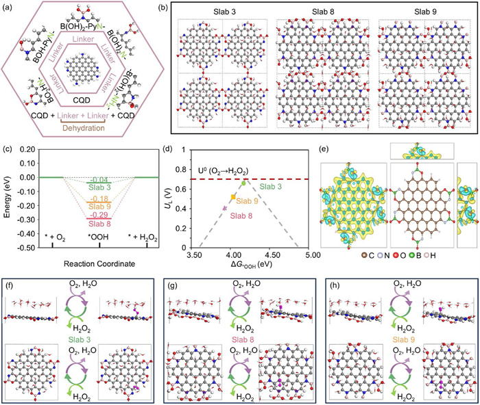
To elucidate the mechanism of converting 0D CQD to 2D CN-B-x carbon nanosheets, density functional theory (DFT) calculations were conducted to explore possible bond configurations among B, N, and O as linkages between two N-CQDs. Since the N–B–O– crosslinker is formed by the mixture of boric acid with N-CQDs, five potential linker configurations as proposed in our previous work [8] was applied for the subsequent bonding formation between two N-CQDs (Fig. 2a). Dehydration reactions between linkers initiate N–B–O– crosslinker formation between N-CQDs, with possible configurations displayed in Figs. S1-S5 (Supporting information). Following optimization and analysis of intermediate configurations and hydration effects via calculations, three possible slab structures were identified, as shown in Fig. 2b. Slab 3 results from dehydration between two BO2HN- linkers and slab 8 is produced by dehydration within two or three B(OH)2-PyN- linkers, while slab 9 is generated by dehydration between B(OH)2-PyN- and BOH-PyN- linkers. The details of these selection processes are described in the computational model (Supporting information). The Gibbs free energy diagram (Fig. 2c) indicates that slab 3 displays the lowest reaction energy barrier (0.04 eV), followed by slab 9 (0.18 eV) and slab 8 (0.29 eV). This trend aligns with the volcano plot in Fig. 2d, where the proximity of slab 3 to the apex of peak indicates its superior catalytic performance, followed by slab 9 and slab 8. Charge density difference (CDD) analysis in Fig. 2e further clarifies these findings. Slab 3 undergoes significant electronic redistribution throughout the entire structure after the formation of N–B–O– crosslinkers, suggesting the enhanced activation of inner carbon atoms and increased electron transfer capacity. In contrast, slab 8 and 9 exhibit electron redistributions primarily localized to the crosslinker part between two CQDs (Fig. S5), reducing their catalytic effectiveness compared to slab 3. The 2e- ORR pathway, including key intermediates like -OOH, was further examined on these slabs (Figs. 2f–h and Fig. S6 in Supporting information). In slab 3, the -OOH proton is inclined to interact with water molecules in the explicit water layer, highlighting the critical role of electrolyte in accurately simulating catalytic behavior under realistic conditions.
Transmission electron microscopy (TEM) images confirmed a uniform distribution of monodisperse nanodots, with average size of 5.04 nm for N-CQD (Fig. 3a). High-resolution TEM (Fig. 3b) exhibited clear diffraction patterns with spacings of 0.272 nm, corresponding to the (100) hexagonal plane of graphite, indicating high crystallinity [12,13]. Atomic force microscopy (AFM) images (Fig. 3c) revealed the CQD consisted of several graphite layers [14,15], with average thicknesses of 3.13 nm. Subsequently, boric acid was added to N-CQD in varying mass ratios (1:0, 1:1, 1:2, 1:4, and 1:6) during ball-milling, then the samples were remarked CN-B-0, CN-B-1, CN-B-2, CN-B-3, and CN-B-4, respectively. Interestingly, the TEM reveals an average diameter of 3.30 nanometers for CN-B-0, and its average thickness of AFM of 2.53 nm (Fig. S7 in Supporting information). These findings that ball milling can decrease the size of CQD and increase its thickness. The phenomenon indicated that N-CQD decreased the size after ball milling without the addition of boric acid and formation of N–B–O– crosslinker.
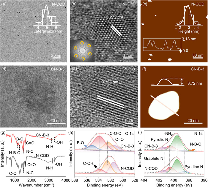
Subsequently, the morphology and structural characteristics of the resulting samples were characterized. TEM images (Fig. 3d and Fig. S7a) showed that all samples formed carbon nanosheet, ranging from 20 nm to 40 nm. The average sizes of the nanosheets 24.85 nm for CN-B-1, 27.94 nm for CN-B-2, and 37.16 nm for CN-B-3, with a slight decrease to 36.51 nm for CN-B-4 (Table S1 in Supporting information). The nanosheets have an area approximately 7–10 times greater than it of N-CQDs, speculating that the formation of carbon nanosheets is from the connection among N-CQDs. Lattice spacings observed in Fig. 3e and Fig. S7b were 0.394 nm for CN-B-1, 0.247 nm for CN-B-2, 0.328 nm for CN-B-3, and 0.248 nm for CN-B-4. AFM images (Fig. 3f and Fig. S7c) revealed that the average thickness of the nanosheets followed the order: CN-B-3 (3.72 nm) > CN-B-4 (3.04 nm) > CN-B-2 (2.63 nm) > CN-B-1 (2.49 nm), reflecting the trend observed in nanosheet size. Notably, CN-B-3 exhibited the largest size and thickness. These results underscore the critical role of N–B–O– crosslinkers in facilitating the conversion of N-CQD to carbon nanosheets and its impact on their morphological and structural properties.
The fluorescence spectra of N-CQD and CN-B-0 (Fig. S8 in Supporting information) show maximum emission peaks at 344 and 336 nm, respectively, indicating that the optical properties of N-CQD remain unchanged after ball-milling treatment. Raman spectroscopy (Fig. S9 in Supporting information) reveals two distinct peaks around 1350 and 1550 cm−1, corresponding to the disordered D-bands and crystalline G bands of graphite [16,17]. Notably, a decrease in the ID/IG ratio signifies an increased degree of graphitization and a larger sp2 domain within the CQD, revealing the strengthened conductivity of the treated CN-B-0. Raman analysis of the carbon nanosheets (Fig. S9) also shows two prominent peaks, with the ID/IG ratios in the order: CN-B-3 (0.61) = CN-B-4 (0.61) < CN-B-2 (0.71) < CN-B-1 (0.72), indicating that CN-B-3 and CN-B-4 possess the highest graphitization degree. X-ray diffraction (XRD) analysis (Fig. S10 in Supporting information) reveals distinct peaks for N-CQD and CN-B-0 at 20.52° and 20.33°, respectively, corresponding to the (002) crystal face of graphite [18]. The peak shift from N-CQD to CN-B-0 is attributed to increased crystal face spacing induced by ball milling. Fig. S10 shows that all samples exhibit distinct diffraction peak, specifically CN-B-1 (19.07°), CN-B-2 (25.67°), CN-B-3 (20.74°), and CN-B-4 (25.32°), which also correspond to the (002) crystal face of graphite. According to Bragg’s law, increased lattice spacing shifts XRD peaks to lower angles, consistent with the observed HRTEM lattice spacing and following Bragg’s law.
To elucidate the impact of the structure on electrocatalytic activities, the elemental valence states were investigated using Fourier-transform infrared (FT-IR) and X-ray photoelectron spectroscopy (XPS) characterization techniques. FT-IR spectroscopy (Fig. 3g and Fig. S11 in Supporting information) was employed to reveal characteristic absorption bands and stretching vibration bands for nitrogen and oxygen functional groups in both types of N-CQD, including -OH at 3331 cm−1, N–H at 1305.3 cm−1 and 2975 cm−1, C=O at 1668.5 cm−1, N–C at 1616.3 cm−1, and C–O at 1306.2 cm−1. Compared with N–CQD and CN-B-3, the new peaks of B–O at 1136 cm−1, and 1171 cm−1 in the CN-B samples corresponds to the N–B–O tensile vibration (Fig. 3g) [19]. The findings conclusively illustrate the successful integration of the boron element, derived from boric acid, into the nanosheets. XPS characterizations were conducted to further investigate the chemical composition and bonding properties of these samples. The survey spectra identified the presence of C, O, and N elements in both types of N-CQD (Fig. S12 in Supporting information). The fitted C 1s spectra of N-CQD showed peaks at 284.8 eV (C—C/C=C), 285.4 eV (C—N), 286.3 eV (C—O), and 288.2 eV (C=O) [20]. The O 1s spectra of N-CQD (Fig. 3h and Fig. S12) included peaks at 531.5 eV (C=O), 532.6 eV (C—O—C), and 533.8 eV (C—OH) [21,22]. The N 1s spectra of N-CQD (Fig. 3i and Fig. S12) revealed peaks can be categorized into pyridine N (398.6 eV), pyrrole N (400.5 eV), graphite N (401.3 eV), and -NH2 (399.6 eV) [23,24].
In the XPS survey spectra (Fig. S13 in Supporting information), compared with N-CQD and CN-B-0, a weak peak of B-C at 191.3 eV confirms the presence of boron in CN-B-x samples [25]. Furthermore, the high-resolution XPS spectra further revealed additional peaks at 283.7 eV (C–B bond) (Fig. S13) [26,27], 534.8 eV (B–O bond) (Fig. 3h) [28], and 398.2 eV (N–B–O bond) (Fig. 3i) [29]. Meanwhile, the high-resolution B 1s spectra displays three main peaks at 191.2, 192.7, and 193.6 eV (Fig. S14 in Supporting information), corresponding to B–C, N–B–O, and B–O bonds [30], respectively, confirming successful formation of N–B–O– crosslinker in carbon nanosheets. The boron atoms were found to modify the carbon skeleton by interlacing in the carbon nanosheet, with their three valence electrons acting as electron acceptors, thereby altering the electronic structure and enhancing the rate capability of the carbon nanosheets [30]. Table S2 (Supporting information) shows a successive increase in boron content from CN-B-1 to CN-B-3, followed by a decrease in CN-B-4, with the N–B–O– content following the same trend (Table S3 in Supporting information). The B 1s XPS shifts stem from varying boron bonding configurations (B–C, N–B–O, B–O) and electron density redistribution. Higher N–B–O– content (e.g., CN-B-3) increases binding energy due to stronger electron withdrawal, while structural order and crosslinking efficiency further modulate the shifts. The results suggest that the N–B–O– crosslinker is pivotal in transforming N-CQD to carbon nanosheets, influencing their size and thickness. Electrochemical tests demonstrated the relationship between nanosheet size, the content of N–B–O– crosslinker, and H2O2 synthesis properties.
The reduction of O2 to H2O2 on all electrocatalysts was evaluated using a rotating ring disk electrode (RRDE) with a calibrated collection efficiency of 0.249 (Fig. S15 in Supporting information) [31]. In an O2-saturated 0.1 mol/L KOH solution, the ring electrode on the 1600 RPM was held at 1.21 V vs. RHE to oxidize the H2O2 formed at the disk electrode. The optimal catalyst load was determined to 0.051 mg/cm2. Linear sweep voltammetry (LSV) measurements from the RRDE (Fig. 4a and Fig. S16 in Supporting information) showed the disk electrode current (solid line) generated by O2 reduction, while the ring electrode current (dashed line) generated by H2O2 oxidation. CN-B-3 exhibits a low disk current (ID) and a high ring current (IR), with an IR over 0.5 mA/cm2 (0.2 V vs. RHE), outperforming N-CQD, CN-B-0, CN-B-1, CN-B-2, and CN-B-4. Furthermore, CN-B-3 demonstrates a higher diffuse-limited current density at 0.5 V vs. RHE, indicating its superior mass transport and catalytic conversion efficiency in the ORR process [32].
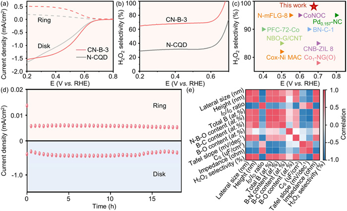
The relationship between H2O2 selectivity, electron transfer number (n) and applied potential was calculated (Fig. 4b and Fig. S17 in Supporting information) [33]. At 0.68 V vs. RHE, CN-B-3 achieved a high H2O2 selectivity of 98.4%, significantly surpassing N-CQD (58.5%), CN-B-0 (63.1%), CN-B-1 (66.5%), CN-B-2 (73.2%), and CN-B-4 (91.3%). Electrochemical impedance spectroscopy (EIS) results (Fig. S18 in Supporting information) revealed the characteristic semicircular feature in the high-frequency region. CN-B-3 exhibits the smallest EIS radius, indicating excellent charge transfer kinetics [34,35]. The Tafel slope of CN-B-3 is the lowest as 73.5 mV/dec, compared to N-CQD (91.6 mV/dec), CN-B-0 (86.3 mV/dec), CN-B-1 (103.1 mV/dec), CN-B-2 (80.5 mV/dec), and CN-B-4 (93.1 mV/dec) with larger slopes (Fig. S19 in Supporting information), further confirming CN-B-3’s superior ORR kinetics [11]. Double-layer capacitance measurements, indicative of electrochemical surface area (ECSA), showed that CN-B-3 (slope 27.82 ɥF/cm2) has the largest ECSA among all materials (Figs. S20 and S21 in Supporting information), aligning with its status as the most active catalyst for H2O2 production [36]. Compared with common metal materials and other carbon-based materials, the catalytic activity of CN-B-3 for 2e- ORR is significantly superior (Fig. 4c) [37-42]. In addition to catalytic activity, stability during the reaction is also crucial. The stability of CN-B-3 was assessed through continuous generation of H2O2 for 18 h, with the ring current and disk current of H2O2 maintaining 92.2% and 88.7% of their original values, respectively, indicating the structural stability of the active site under electrochemical production conditions (Fig. 4d, Figs. S22 and S23 in Supporting information). A heat map (Fig. 4e) was used to analyze the structure-performance relationship, showing the correlation between the structural characteristics, functional group content, and H2O2 selectivity. Blue signifies a negative correlation, while red indicates a positive correlation. As presented in Fig. 4e, the total content of B is positively correlated with the H2O2 selectivity, while the N–B–O– crosslinker content shows a more pronounced positive correlation with H2O2 selectivity than B–C and B–O bonds.
Through the RRDE tests assessments, the CN-B-3 catalyst emerged as a nearly ideal electrocatalyst for the 2e- ORR. To further elucidate its potential, a flow cell setup (Fig. 5a) was assembled. The setup was designed to operate within 1.0 mol/L KOH and 10 mmol/L ethylenediaminetetraacetic acid (EDTA) electrolytes, with the peristaltic pump independently controlling the anode and cathode. The CN-B-3 loaded gas diffusion layer electrode, with a concentration of 1 mg/cm2, served as the working electrode, while a Pt foil and Ag/AgCl electrode were designated as the counter electrode and reference electrode, respectively. Upon conducting LSV tests, a significant surge in current density was observed (Fig. S24 in Supporting information). Notably, the concentration of H2O2 exhibited a linear increase reaction time, suggesting a consistent rate of its formation. After 50 h, a total H2O2 production of 213 mmol/L was achieved, accompanied by a gradual decrease in Faraday efficiency (FE%) (Figs. 5b and c). This decrement can be attributed to enhanced reduction of H2O2 with concentrated H2O2 solution or the decomposition of H2O2 in an alkaline milieu [33]. These findings conclusively demonstrate that CN-B-3 catalyst exhibits excellent activity and stability not only in RRDE testing but also within the flow cell setup for 2e- ORR.
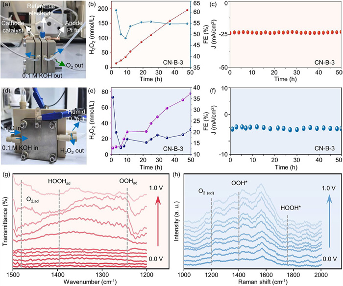
To achieve direct electrosynthesis of pure H2O2, 2e- ORR experiments were carried out in a customized solid-state electrolyte (SSE) electrolyze (Fig. 5d). The catalyst ink was uniformly sprayed onto carbon paper, forming a gas diffusion electrode with a loading of ~1 mg/cm2 as the cathode. In this setup, an SSE layer (Amberlite® IR 120 Strong Acid Ion Exchange Resin) was positioned between the cathode and anode chambers. An anion exchange membrane (Sustainion TM X37-50) and a proton exchange membrane (Nafion 117) were employed to isolate the SSE from the respective chambers, effectively preventing flooding and cross-contamination. Deionized water was supplied to this porous SSE layer using a peristaltic pump to bring out the generated H2O2. The cathode chamber was supplied with humidified O2 gas, while the anode chamber was circulated with 0.1 mol/L KOH aqueous solution at a flow rate of 10 mL/min to facilitate the OER. As shown in Fig. 5e, the CN-B-3 catalyst enabled efficient H2O2 production, achieving a high concentration of 77 mmol/L. Comparative performance analysis of CN-B-3 between CN-B-3 and other reported electrocatalysts in alkaline media, as summarized in Table S4 (Supporting information). The FE displays an initial decline followed by a modest rebound, suggesting potential stabilization or reactivation of catalytic sites during prolonged operation [43,44]. The long-term stability of H2O2 electrosynthesis was systematically evaluated under continuous operation. As illustrated in Fig. 5f, the system demonstrates exceptional operational durability, maintaining continuous and stable H2O2 production at the cathode for over 50 h without significant performance degradation, underscoring the excellent operational durability and practical applicability of the CN-B-3-based SSE system.
To gain a fundamental insight into the 2e- ORR mechanisms of CN-B-3 catalyst, we utilized in situ attenuated total reflectance infrared (ATR-IR) spectrometry to meticulously monitor the dynamic evolution of the crucial surface species as they participated in the ORR process. In an environment rich with oxygen, utilizing a 0.1 mol/L KOH electrolyte and a platinum counter electrode, a remarkable decline in potential was observed, ranging from 0 V to 1.0 V (Fig. 5g) [45]. The initial potential of 0 V regarded as the background for the subsequent spectra was collected, and the IR spectra were recorded at each potential step under O2. For the in-situ ATR-IR spectra, the band observed at 1479 cm−1 closely correlated with the presence of adsorbed molecular oxygen O2(ad). As the applied potential dips below 0.7 V (at about onset potential), the adsorption of superoxide OOH(ad) and hydroperoxide HOOH(ad) are clearly observed at respective wavenumbers 1225 and 1394 cm−1, respectively [39,46,47]. This finding suggests a preference for 2e- ORR pathway for CN-B-3 catalysts.
The Raman spectroscopy analysis conducted in situ for CN-B-3 revealed a comprehensive profile of its intermediate species under varying applied potentials, as illustrated in Fig. 5h. Three peaks appeared at 1242, 1429, and 1775 cm−1, with their intensities exhibiting a progressive enhancement as the potential varied from 0 V to 1.0 V. The peak at 1242 cm−1 was identified as the stretching vibration of B–O within the adsorbed O2(ad), and the peaks at 1429 and 1775 cm−1 were assignable to the vibration’s modes of the adsorbed OOH* on C=O and HOOH* on B–C–N, respectively [48]. The advent of these signals revealed that CN-B-3 carbon nanosheets catalyzed the 2e- ORR by adsorbing O2, generating OOH* and HOOH* intermediates, and promoting the formation of H2O2.
In summary, we employed a hydrothermal-ball milling tandem strategy to convert N-CQD into N, B, O, co-doped carbon nanosheets. Initially, N-CQD was fabricated through a hydrothermal reaction using p-phenylenediamine and cinnamonitrile as precursors, followed by high-speed mechanical ball milling with boric acid to form N–B–O–, a crosslinker, facilitating the transformation from 0D CQD into 2D carbon nanosheets. The size and thickness of N-CQD decreased after ball milling without boric acid, and the addition of boric acid facilitated the formation of N–B–O– crosslinkers between the edges of N-CQD. An increase in N–B–O– functional group content increases the size and thickness of the resulting carbon nanosheets and correlates positively with the electrochemical performance for H2O2 generation. CN-B-3, with the highest N–B–O– crosslinker content (0.38 at%), exhibited the largest size of 37.16 nm, the highest graphitization degree and superior performance. It achieved an H2O2 selectivity of 98.4% at 0.68 V vs. RHE, a low Tafel slope (73.5 mV/dec), and a high ring current density (0.46 mA/cm2 at 0.4 V vs. RHE). Additionally, CN-B-3 showed the smallest impedance and the largest ECSA slope (27.82 ɥF/cm2), outperforming common metal materials and other carbon-based materials. After an 18 h stability test, CN-B-3 maintained 92.2% of its initial ring current and 88.7% of its initial disk current, indicating high stability. In a flow cell experiment, the CN-B-3 catalyst demonstrated hydrogen peroxide yield of 213 mmol/L. Following an extensive 50-h stability assessment, the catalyst’s robust performance was further highlighted by its exceptional stability. To further improve the electrocatalytic ORR performance, we employed a solid-state electrolyte reactor system, which achieved a remarkable H2O2 production concentration of approximately 77 mmol/L and 50-h stability in the solid-state electrolyte cell. Furthermore, in situ ATR-IR and in situ Raman unveiled the CN-B-3 carbon nanosheet catalyst enhances the adsorption of O2 and facilitates the stabilization of the key intermediates (OOH* and HOOH*), which can improve the 2e- ORR performance. The DFT calculations identified the possible connected structures between several N-CQDs after mixing with H3BO3. Several configurations of N–B–O– crosslinker can promote the 2e- ORR. The bonding of B with a nitrogen atom dangling from the carbon ring promotes the 2e- ORR more effectively than the case when B is bonded to pyridinic-N within the carbon framework. This study presents a novel approach for converting 0D CQD to 2D carbon nanosheets, contributing to the development for efficient and sustainable energy conversion technologies, and highlighting the potential of metal-free N–B–O– crosslinked carbon nanosheets as electrocatalysts.
The authors declare that they have no known competing financial interests or personal relationships that could have appeared to influence the work reported in this paper.
Leping Xie: Writing – original draft, Investigation, Data curation. Caihong Liang: Writing – original draft, Investigation, Data curation. Huazhang Guo: Writing – original draft, Investigation, Data curation. Kang Wang: Investigation. Shihao Zhang: Investigation. Jiye Zhang: Investigation. Yeng Ming Lam: Writing – review & editing, Supervision, Project administration. Zheng Liu: Writing – review & editing, Supervision, Project administration. Liang Wang: Writing – review & editing, Supervision, Project administration, Funding acquisition.
This project was funded by the Shanghai Pujiang Program (No. 21PJD022) and the National Natural Science Foundation of China (No. 21901154). This work is supported by Shanghai Technical Service Center of Science and Engineering Computing, Shanghai University.
Supplementary material associated with this article can be found, in the online version, at doi:
Y. Pang, H. Xie, Y. Sun, J. Mater. Chem. A 8 (2020) 24996–25016. doi: 10.1039/d0ta09122g
S. Yang, A. Verdaguer-Casadevall, L. Arnarson, et al., ACS Catal. 8 (2018) 4064–4081. doi: 10.1021/acscatal.8b00217
S. Siahrostami, S.J. Villegas, A.H.B. Mostaghimi, et al., ACS Catal. 10 (2020) 7495–7511. doi: 10.1021/acscatal.0c01641
H. Sun, H. Awada, H. Lei, et al., Mater. Today Catal. 4 (2024) 100038.
Y. Xia, X. Zhao, C. Xia, et al., Nat. Commun. 12 (2021) 4225. doi: 10.1038/s41467-021-24329-9
G.F. Han, F. Li, W. Zou, et al., Nat. Commun. 11 (2020) 2209. doi: 10.1038/s41467-020-15782-z
X. Liu, S. Pang, L. Zeng, et al., Chem. Commun. 58 (2022) 8686–8689. doi: 10.1039/d2cc03172h
M. Fan, Z. Wang, K. Sun, et al., Adv. Mater. 35 (2023) 2209086. doi: 10.1002/adma.202209086
G. An, K. Wang, M. Yang, et al., Molecules 30 (2025) 953. doi: 10.3390/molecules30040953
S. Fu, B. Tang, Z. Wang, et al., Chem. Eng. J. 500 (2024) 157207. doi: 10.1016/j.cej.2024.157207
B. Guo, R. Ma, Z. Li, et al., Nano-Micro Lett. 12 (2020) 20. doi: 10.1007/s40820-019-0364-z
W. You, W. Zou, S. Jiang, et al., Carbon Neutral. 3 (2024) 245–284. doi: 10.1002/cnl2.120
Q. Ni, S. Zhang, K. Wang, et al., J. Mater. Chem. A 12 (2024) 31253. doi: 10.1039/d4ta06855f
Z. Jin, M. Yuan, H. Li, et al., Adv. Funct. Mater. 26 (2016) 5284. doi: 10.1002/adfm.201601570
N. Park, Y. Heo, J.W. Yang, et al., ACS Nano 19 (2025) 8692. doi: 10.1021/acsnano.4c15283
J. Tao, L. Xu, H. Jin, et al., Adv. Powder Mater. 2 (2023) 100091. doi: 10.1016/j.apmate.2022.100091
X. Qin, M. Yang, P. Yin, et al., Mater. Today Catal. 3 (2023) 100026.
S. Chen, T. Luo, K. Chen, et al., Angew. Chem. Int. Ed. 60 (2021) 16607–16614. doi: 10.1002/anie.202104480
M. Li, L. Qiu, I. Popovs, et al., Angew. Chem. Int. Ed. 62 (2023) e202302684. doi: 10.1002/anie.202302684
H. Liu, S. Zhu, Y. Zhang, et al., Small 19 (2023) 2204119. doi: 10.1002/smll.202204119
M. Fan, J. Xu, Y. Wang, et al., Chem. Eur. J. 28 (2022) e202201996. doi: 10.1002/chem.202201996
J. Sun, N. Guo, T. Song, et al., Adv. Powder Mater. 1 (2022) 100023. doi: 10.1016/j.apmate.2021.11.009
W. Hou, Y. Li, K. Wang, et al., Sci. China Chem. 68 (2025) 5293–5301. doi: 10.1007/s11426-025-2603-0
K. Wang, K. Huang, Z. Wang, et al., Small 21 (2025) 2502733. doi: 10.1002/smll.202502733
Z. Tian, Q. Zhang, L. Thomsen, et al., Angew. Chem. Int. Ed. 61 (2022) e202206915. doi: 10.1002/anie.202206915
Z. Yao, M. Hu, Z. Iqbal, et al., ACS Catal. 10 (2020) 160–167. doi: 10.1021/acscatal.9b03610
L. Liu, X. Zhang, D. Zhang, et al., Chem. Eng. J. 473 (2023) 145454. doi: 10.1016/j.cej.2023.145454
W. Sun, Y. Zhang, G. Yin, et al., Adv. Funct. Mater. 34 (2024) 2402346. doi: 10.1002/adfm.202402346
W. Lin, H. Chen, G. Lin, et al., Angew. Chem. Int. Ed. 61 (2022) e20220780.
J.J. Yao, C. Liu, J.Y. Li, et al., Rare Met. 42 (2023) 2307–2323. doi: 10.1007/s12598-023-02265-5
K. Zhao, Y. Su, X. Quan, et al., J. Catal. 357 (2018) 118–126. doi: 10.1016/j.jcat.2017.11.008
Z. Yang, Y. Gao, L. Zuo, et al., ACS Catal. 13 (2023) 4790. doi: 10.1021/acscatal.2c06092
Y. Guo, R. Zhang, S. Zhang, et al., Energy Environ. Sci. 15 (2022) 4167–4174. doi: 10.1039/d2ee01797k
X. Hu, Y. Li, X. Wei, et al., Adv. Powder Mater. 1 (2022) 100024. doi: 10.1016/j.apmate.2021.11.010
Z. Wang, H. Guo, S. Zhang, et al., Chem. Eng. J. 512 (2025) 162752. doi: 10.1016/j.cej.2025.162752
X. Ma, J. Du, H. Sun, et al., Appl. Catal. B: Environ. 298 (2021) 120543. doi: 10.1016/j.apcatb.2021.120543
N. Wang, X. Zhao, R. Zhang, et al., ACS Catal. 12 (2022) 4156–4164. doi: 10.1021/acscatal.1c05633
X. Zhao, Q. Yin, X. Mao, et al., Nat. Commun. 13 (2022) 2721. doi: 10.1038/s41467-022-30523-0
C. Tang, L. Chen, H. Li, et al., J. Am. Chem. Soc. 143 (2021) 7819–7827. doi: 10.1021/jacs.1c03135
L. Li, C. Tang, Y. Zheng, et al., Adv. Energy Mater. 10 (2020) 2000789. doi: 10.1002/aenm.202000789
Y. Tong, J. Liu, B.J. Su, et al., Carbon Energy 6 (2023) e378.
E. Jung, H. Shin, B.H. Lee, et al., Nat. Mater. 19 (2020) 436–442. doi: 10.1038/s41563-019-0571-5
H. Yin, J. Yuan, J. Wang, et al., Energy Environ. Sci. 18 (2025) 2231–2242. doi: 10.1039/d4ee05796a
M.D. Zhang, J.R. Huang, C.P. Liang, et al., J. Am. Chem. Soc. 146 (2024) 31034–31041. doi: 10.1021/jacs.4c10675
Z. Liang, C. Lee, J. Liu, et al., Mater. Today Catal. 2 (2023) 100011.
S. Nayak, I.J. McPherson, K.A. Vincent, Angew. Chem. Int. Ed. 57 (2018) 12855–12858. doi: 10.1002/anie.201804978
H. Li, P. Wen, D.S. Itanze, et al., Nat. Commun. 11 (2020) 3928. doi: 10.1038/s41467-020-17584-9
Y. Wang, Y. Zhou, Y. Feng, et al., Adv. Funct. Mater. 32 (2022) 2110734. doi: 10.1002/adfm.202110734

Figure 2 Density functional theory of possible bond linkage amongst B, N, O between two N-CQDs. (a) The basic structure of N-CQD and 5 different linkers. Color code: C, grey; N, blue; O, red; B, light pink; H, white. (b) Three basic (2 × 2) slab structures with water layer: slab 3, slab 8, and slab 9. (c) The Gibbs free energy diagram of optimal 2e- ORR pathway at U = 0.7 V over slab 3, slab 8, and slab 9. (d) The volcano plot between ΔG*OOH and Ulimited (UL) for different carbon nanosheets: slab 3, slab 8, and slab 9. (e) The charge density difference diagram of slab 3. Yellow isosurface (charge accumulation), cyan isosurface (charge depletion). Iso-surface level = 0.01 e/Bohr3 for all slab structures. Δρ = ρ(slab + linkers) - ρ(slab) - ρ(linkers). The schematic of ball-and-stick structure about the optimal 2e- ORR pathway over (f) slab 3, (g) slab 8 and (h) slab 9.

Figure 3 Morphological and structural characterizations of N-CQD and carbon nanosheets. (a) The TEM image of N-CQD. (b) The HRTEM image of N-CQD. (c) AFM image and corresponding height profiles of NCQD. (d) The TEM image of CN-B-3. (e) The HRTEM image of CN-B-3. (f) AFM image and corresponding height profiles of CN-B-3. (g) FT-IR spectra, (h) XPS O 1s spectra, and (i) N 1s spectra of N-CQD and CN-B-3.

Figure 4 Electrocatalytic performance and in situ technical characterizations of N-CQD and CN-B-x carbon nanosheets. (a) ORR polarization curves of the as-prepared N-CQD and CN-B-3 on RRDE at 1600 rpm in O2-saturated 0.1 mol/L KOH. (b) Calculated H2O2 selectivity under various potentials of the as-prepared N-CQD and CN-B-3. (c) Comparing H2O2 selectivity performance of the CN-B-3 with common other materials. (d) Long-term stability test of the CN-B-3 at 0.68 V vs. RHE using a RRDE. (e) Heat maps indicating Pearson correlation between CN-B-x and different physicochemical properties.

Figure 5 H2O2 production in a flow cell and degradation application of CN-B-3. (a) The photo of the flow cell device. (b) The concentration of produced H2O2 and corresponding H2O2 faradaic efficiency of the CN-B-3 under various reaction durations using flow cell. (c) Stability test of the CN-B-3 in a flow cell. (d) Schematic of H2O2 electrosynthesis vis solid-state-electrolyte cell. (e) The concentration of produced H2O2 and corresponding H2O2 faradaic efficiency of the CN-B-3 under various reaction durations using solid-state-electrolyte cell. (f) Stability evaluation of the CN-B-3 in a solid-state-electrolyte cell. (g) In situ ATR-IR spectra recorded during the constant potential steps of CN-B-3 in O2-saturated 0.1 mol/L KOH electrolyte, at various potentials. (h) In situ Raman spectra recorded during the constant potential steps of CN-B-3.

 扫一扫看文章

扫一扫关注我们
 DownLoad:

 下载:
下载:
 下载:
下载: