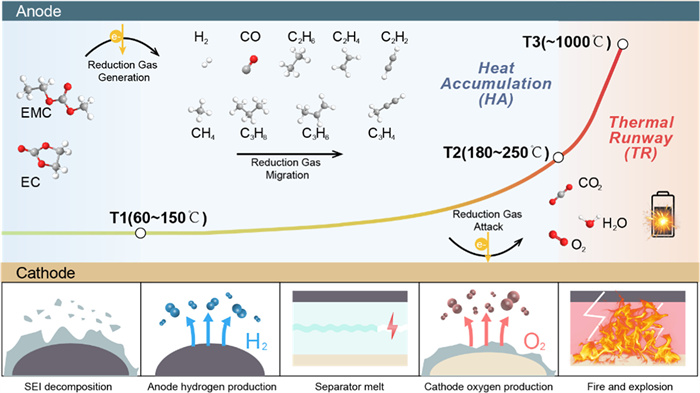
Figure 1.
Schematic diagram of thermal runaway mechanism.
The role of flame-retardant electrolytes in lithium-ion batteries: Custom design for improved battery-level safety
Yaxuan Fu , Xiaozhi Jiang , Chenyang Shi , Long Chen , Zhendong Yang , Mengran Wang , Bo Hong , Faping Zhong , Yanqing Lai

Achieving carbon neutrality necessitates a global transition from fossil fuels to renewable energy sources, with batteries serving as a crucial technology for energy conversion, transportation, and storage [1-3]. Compared with other battery technologies, lithium-ion batteries (LIBs) have the advantages of high energy density (>250 Wh/kg), long cycle life (>3500 cycles), high voltage (>3.5 V), low cost, and have been widely used in electric vehicles, mobile devices, and energy storage systems [4]. However, with the continuous expansion of the application scale of LIBs, as well as the continuous improvement of energy density requirements, relieving the safety issues for lithium-ion batteries are in urgent need. This insecurity involves several aspects of the separators [5,6], the electrode materials (especially the anode [7]), and the electrolytes.
Electrolyte plays a very important role in the thermal runaway process of LIBs [8]. Conventional lithium-ion battery electrolyte usually consists of lithium hexafluorophosphate and organic carbonate with low flash point, highly flammable and poor electrochemical stability [9,10]. While solid electrolytes have been proposed as an alternative to conventional liquid electrolytes due to their high thermal stability and mechanical strength [11,12]. However, these solid electrolytes are not as effective as liquid electrolytes in terms of ionic conductivity, interfacial compatibility, and manufacturing cost [13,14], leading to difficulties in replacing liquid electrolytes in the short term. Concurrently, if the liquid electrolyte can achieve non-flammability, which could attain both high electrochemical performance and high safety. Therefore, the development of non-flammable liquid electrolytes has attracted widespread attention. Most non-flammability strategies are to introduce flame-retardant additives/solvents into the electrolyte [15-17], which are reported to be effective to increase the safety of the battery to a certain extent, but sacrifice the battery cycling stability and interfacial stability.
In this situation, rational design of flame-retardant electrolytes for high-safety and high-performance batteries is essential. However, current works can hardly combine the flame-retardant electrolyte design with the battery safety directly, which could be assigned to the one-sided assessment of electrolyte. Herein, based on the latest theoretical understanding of battery thermal runaway, the role of flame-retardant electrolytes for the battery thermal runaway process to guide the customized design of flame-retardant electrolytes is described in this review. Furthermore, the solvation structure design principle for different flame-retardant electrolytes and the systematic safety characterization at the material and battery levels are also summarized in this work. This review shed light on the design of flame-retardant electrolytes for high-safety batteries.
Thermal runaway (TR) is the root cause of smoke, fire and explosion in LIBs. As shown in Fig. 1, a typical TR process consists of two characteristic phases (heat accumulation (HA), thermal runaway (TR)) and three characteristic temperatures (T1, T2, and T3) [3,18], which are defined based on adiabatic accelerated calorimetry (ARC). Before the T1 temperature, the lithium-ion battery is in the normal temperature range. The total battery heat production mainly consists of reversible heat production (redox reactions), irreversible heat production (ohmic and polarization heat production) and side reaction heat production [19]. Due to improper operation (mechanical abuse, electrical abuse and thermal abuse [20]) the battery temperature reaches T1 (60–150 ℃) and enters the HA stage. The internal temperature of the battery begins to rise slowly, typically at a rate of 0.02–0.05 ℃/min [21]. Reactions include decomposition of the solid electrolyte interfacial (SEI), anode-electrolyte reactions, and decomposition of the electrolyte itself [14]. The total HA duration can last from a few minutes to several days [22,23]. After this, the battery temperature reaches the thermal runaway threshold T2 (180–250 ℃) [24,25]. Accompanied by several lethal triggers, including separator collapse [26], dramatic release of oxygen from the cathode [27], and significant hydrogen production from the anode [28], the battery enters an intense TR stage with a temperature rise rate of 60–104 ℃/min. According to a rough estimation, the heat generated by the internal short circuit is only 2%, and the chemical exothermic reaction accounts for 98% [29]. After an intense heat release in the TR stage, the battery temperature rises to a maximum value of T3 (~1000 ℃) within a few seconds [22], resulting in catastrophic damage that is difficult to control. With the development of high energy density battery systems, more energy is compressed into a limited volume/weight, increasing the difficulty of heat dissipation from the battery, and thus battery TR tends to be triggered more easily and violently [30,31].
As one of the most flammable components in LIBs, electrolytes have an important impact on the thermal runaway process of batteries, especially in the HA stage. The specific causes are as follows: Firstly, organic carbonates themselves have low flash and boiling points and are usually highly volatile and flammable, and these solvents are prone to cause fires when exposed to air [32,33]. Secondly, conventional electrolytes are chemically unstable. LiPF6 is sensitive to moisture and decomposes easily above 60 ℃, where it can produce the strong Lewis acid phosphorus pentafluoride (PF5), and PF5 reacts with organic solvents to produce HF and other reducing gases [34-36]. As the temperature increases above 100 ℃, the carbonate solvents come into direct contact with the lithiated anode and begin to undergo more intense redox reactions. This is typically manifested by a steadily increasing heating slope (>1 ℃/s) in ARC tests or a significant exothermic peak on DSC results [3], corresponding to the characteristic T2 temperature of the TR process. In addition, the organic solvent decomposes itself at 200 ℃ to produce CO2 and H2O [37-39]. Thirdly, the electrolyte is unstable to the interface. The narrow electrochemical window of the electrolyte itself makes it prone to side reactions at the cathode and anode, while the actual SEI formed by the conventional carbonate electrolyte is fragile and unstable, which leads to inhomogeneous lithium deposition [40]. The generated lithium dendrites eventually puncture the separator, resulting in direct cathode-anode contact and the subsequent triggering of thermal runaway, which corresponds to a T3 temperature. Lastly, it promotes the accumulation of flammable gases. During the battery HA stage, some reducing gases (e.g., H2, CO, CH4, C2H4, and C2H6) are continually produced, which migrate inside the battery and attack the cathode crystals, especially the gases containing unsaturated bonds, triggering the release of more oxygen at high temperatures and generating large amounts of heat and gases [41].
Tailored electrolyte design can address safety issues and is an important development direction for future high safety, high energy density LIBs. Considering that TR usually occurs within 0.1 s [42], it is difficult for safety countermeasures to take effect during TR. Even stabilizing cathode crystals [43] or trapping oxygen [44] can only slightly delay TR, but not avoid it. whereas the side reaction occurs moderately in the HA phase, which usually lasts for several minutes or days, implying the possibility of cutting off the heat release. Furthermore, the heat change in the HA phase happens to be closely related to the electrolyte [41]. The basic strategies are as follows: (1) The use of intrinsically safe functional solvents, such as phosphate esters that trap free radicals, and ionic liquids that are difficult to volatilize, can reduce the likelihood of heat build-up and outgassing, as well as lowering T2 and T3 temperatures. (2) Build an electrolyte interface layer SEI with high thermal stability to delay the T1 temperature and the HA stage. (3) Constructing a solvated structure with a stable and wide electrochemical window to achieve battery-level safety and reduce the possibility of thermal runaway in batteries under thermal and electrical abuse.
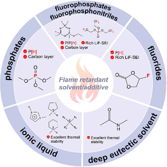
As mentioned above, the development of non-flammable liquid electrolytes that are both flame-retardant and battery-grade safe is of paramount importance. It is widely acknowledged that the design of electrolytes is a complex, systematic project. Consequently, the introduction of flame-retardants has an impact on all aspects of battery performance, including thermal stability, electrochemical stability and interfacial stability. This section provides an overview of the most commonly used flame-retardant solvents, including phosphates, fluorides, fluorosphates and fluorophosphonitriles, ionic liquids, and deep eutectic solvents (Fig. 2). Finally, the influence of a particular category of flame-retardant solvents on the battery system is elucidated, along with proposals for optimization strategies.
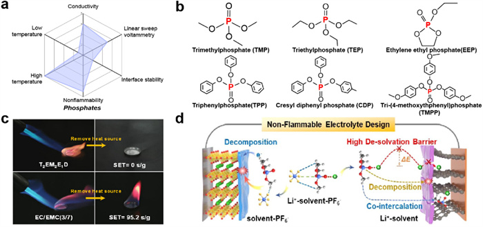
Phosphates are one of the most promising candidates for non-flammable electrolytes for LIBs due to their efficient flame retardancy and low toxicity. Fig. 3a summarizes the relevant properties of phosphates and Fig. 3b shows the structural formulas of commonly used phosphates. They trap reactive free radicals (H and OH radicals) and acids generated by combustion and produce phosphoric acid to promote the formation of a char layer on the surface of the substrate, preventing flame propagation and combustion [45-47]. Common phosphates include linear phosphates (trimethyl phosphate (TMP), triethyl phosphate (TEP), etc.), cyclic phosphates (ethylene ethyl phosphate (EEP), etc.), and aryl-substituted phosphates (triphenylphosphate (TPP), cresyl diphenyl phosphate (CDP), tri-(4-methoxythphenyl)phosphate (TMPP), etc.). Table 1 summarizes the physical properties of the above phosphates, which generally have higher thermal stability than carbonates. This section will analyze the performance characteristics of several types of phosphates from the structural point of view and present their current problems, followed by a discussion of current modification strategies from the point of view of additive introduction and solvation adjustments, and finally present our own viewpoints.
 DownLoad:
CSV
DownLoad:
CSV
| Solvents | Boiling point (℃) | Flash point (℃) |
| TMP | 197 | 148 |
| TEP | 215 | 117 |
| EEP | 100 (0.5 mmHg) | 77 |
| TPP | 370 | 220 |
| CDP | 235–255 | 232 |
| TMPP | 457.8 ± 40 | – |
Phosphates with different structures result in differing performances in batteries, especially in terms of electrochemical and interfacial stability. In detail, linear phosphates with low molecular weight typically exhibit low viscosity, high donor numbers, and low dielectric constants [48,49]. Consequently, linear phosphates exhibit a robust binding energy with Li+ and are susceptible to forming solvent-separated ion pairs (SSIP) in the electrolyte, as well as their inherent weak film-forming ability, showing incompatibility at both graphite and lithium metal anode interfaces, which worsens the cycling performance of the battery [50,51]. For this reason, researchers have improved their solventation ability and enhanced interfacial stability by increasing the number of carbon atoms in the alkyl groups [52] or using cyclic phosphates [53] and aromatic phosphates [54]. For instance, Zhang et al. [52] investigated the solvation capacity and structural adaptability of TEP by modifying the length of the TEP carbon chain. Of the three candidates, triethyl phosphate, tripropyl phosphate and tributyl phosphate, tripropyl phosphate was found to exhibit a balance between solvation ability and salt dissociation ability with better electrochemical performance. Furthermore, cyclic and aromatic phosphates demonstrate superior flame-retardant efficacy compared to linear phosphates, accompanied by additional electrochemical enhancements. Gao et al. [55] added an electrolyte with 10% EEP in the carbonate solvents and found that the self-extinguishing time of the electrolyte containing EEP was only less than half that of the baseline electrolyte. The addition of EEP can delay the sharp voltage rise during overcharging of Li||NCM111 batteries. Yang et al. [56] also found that 10% TMPP can provide overcharge protection for batteries. It is seen that proper structural adjustments can change the behaviour of phosphates in batteries.
In addition to structural adjustments, the introduction of sacrificial additives or the use of lithium salts with better thermal stability can also improve phosphates interfacial incompatibility. On the one hand, the film-forming additives weaken the strong polarity of the P=O bond through dipole-dipole and dipole-ion interactions, allowing more lithium salts or other solvents to undergo solvation sheaths inducing anion-dominated interfacial chemistry. On the other hand, they preferentially decompose to form more homogeneous and stable SEI films, and add inorganic species favorable for Li+ migration, such as LiF. The formation of robust SEI films contributes to the prolongation of the electrochemical lifetime of the battery and the delay of the thermal runaway onset temperature T1. These additives include VC [57], VEC [58], FEC [59], LiNO3 [60] and DTD [49], as well as lithium salts such as LiTFSI [57], LiFSI [61] and LiDFOB [59]. Ming et al. [49] introduced ethylene sulfate (DTD) with high polar surface area and strong Li+ coordination capacity to weaken the Li+-TMP interaction, as well as to partially decompose to form SEI due to the low LUMO of Li+-DTD (Figs. 3c and d). The graphite||NCM811 battery achieved high cycle stability and excellent power generation capability (fast charging rate up to 5 C) at high voltage > 4.3 V and wide temperature range of −50 ℃ to 60 ℃. It is not difficult to see that a small number of additives can have a multiplier effect, but the compatibility, multifunctionality and environmental friendliness of additives to the electrolyte system need to be improved.
It has been demonstrated that modifying the solvation structure by adjusting the phosphate-based electrolyte represents an effective approach to ensure battery safety and cycle stability. In conventional electrolytes, the solvent molecule occupies the initial solventised sheath layer, which readily exposes the instability of the phosphate interface. And this can be compensated by allowing the thermally stable lithium salt to dominate the solventised sheath layer. Cao et al. [61] developed a non-combustible concentrated electrolyte composed of 1:2-LiFSI:TEP. In the concentrated solution, most TEP molecules were coordinated with Li+, which effectively reduced the reaction between TEP and the graphite anode. And the fully charged 18,650 battery was found to withstand the short circuit, puncture and crush tests. Deng et al. [62] formed a FSI--dominated weakly solvated structure by adding FEMC to TEP. This electrolyte enabled the LiCoO2 cell to maintain >79% capacity after 400 cycles at 5 C and 4.6 V. Solemnization adjustments are a long term solution to achieve intrinsic battery safety and performance improvements, but increasing the concentration of lithium salts brings cost anxiety and viscosity issues, so screening for appropriate solvents to weaken the coordination of Li+ with phosphates is a more preferable strategy.
In summary, phosphates are one of the most effective and widely used flame-retardant solvents. They have significant advantages in radical trapping and thermal stabilization. However, their weak film-forming ability and tendency to co-embed with Li+ have historically posed challenges. Currently, improving the structure of phosphates, introducing additives and changing the solvation structure are effective solutions to this problem. Nevertheless, the adjustment of solvation structure exerts the most significant influence on the safety and performance of the battery, especially in terms of wide temperature and fast charging. The latest reports on phosphate-based high safety electrolytes have been summarized in Table 2 [49,61-64].
DownLoad:
CSV
| Electrolyte | σ (mS/cm) | tLi+ | ESW (V) | Battery composition | Cycle preformance | Safety test | Ref. |
| Phosphates | |||||||
| 1 mol/L LiFSI/10 vol% FEC/FEMC:TEP = 3:1 vol% | 4.60 | 0.58 | 4.60 | LCO|| Gr | 74.9% (400 cycles, 5 C, 4.6 V) | SET; pierce; IT In-situ XRD | [62] |
| LiFSI:TEP = 1:2 mol%/5 vol% FEC/0.05 mol/L LiBOB | None | None | 4.30 | LCO||Li | 88.0% (350 cycles, 20 mA/g, 4.3 V) | SET; pierce | [61] |
| 1.2 mol/L LiPF6/6 wt% DTD TMP:EMC:EC = 4.7:3.8:1.5 MR | 5.82 | 0.46 | 4.50 | LCO|| Gr | 83.2% (200 cycles, 1 C, 4.5 V) | SET; In-situ XRD | [49] |
| 1.2 mol/L LiFSI/TEP:BTFE = 1:3 mol% | 1.30 | None | 4.40 | NCM622||Li | 97.0% (600 cycles, 0.33 C/1 C, 4.4 V) | SET | [63] |
| 1.5 mol/L LiNO3/TEP:FEC = 3:1 vol% | None | None | 4.60 | NCM811||Li | 95.5% (1000 cycles, 1 C, 4.3 V) | SET; TA IT+pierce | [64] |
| Fluorides | |||||||
| 1 mol/L LiPF6/FEC/DFEC/EMC/DEC = 1.5:1.5:4:3 vol% | None | 4.60 | LCO||Li | 85.5% (1000 cycles, 1 C, 4.6 V) | None | [78] | |
| 2 mol/L LiPF6/DMC:FEC:FEMC = 3:1:1 vol% | 9.30 | 0.65 | >6.00 | LCO||Li | 74.2% (270 cycles, 1.5 mA/cm2, 4.5 V) | None | [76] |
| LiTFSI:P13FSI:TTE = 1:2:2 mol% | 3.40 | 0.12 | >5.50 | LCO||Li | 80.0% (400 cycles, 0.5 C, 4.3 V) | SET; DSC | [75] |
| 1 mol/L LiPF6/EC:FEMC = 3:7 vol%, 2% VC | 0.40 | None | 5.80 | NCM622||Gr | 82.5% (100 cycles, 0.5 C, 4.5 V, 45 ℃) | SET; DSC | [66] |
| 1 mol/L LiPF6/ETFB:FEC = 1:4 vol% | 4.95 | 0.48 | >5.00 | NCM811||Li | 70.0% (140 cycles, 1 C, 4.5 V) | None | [77] |
| 1 mol/L LiPF6/FEC:EMC:TFEC = 3:3:4 vol% | ~5.00 | None | 5.94 | NCM811||Li | 80.0% (300 cycles, 0.3 C/0.5 C, 4.4 V) | SET; ARC; TA; Pierce+IT | [65] |
| Fluorophosphates and fluorophosphonitriles | |||||||
| 1 mol/L LiTFSI/DME:HFPN = 4:1 vol% | None | 4.30 | LCO||Li | >80.0% (100 cycles, 0.3 C, 4.2 V) | SET | [95] | |
| 0.93 mol/L LiTFSI/TFEP:FEMC:HFE = 1:3:1 vol% | 3.16 | None | 5.10 | NCM622||Li | 88.2% (400 cycles, 0.4 C, 4.6 V) | SET | [96] |
| 0.8 mol/L LiPF6/EC:DEC:HFPN = 1:1.5:1 MR | 5.23 | None | >4.30 | NCM622||Li | 92.9% (200 cycles, 0.5 C, 4.3 V) | In-situ XRD; SET | [97] |
| LiFSI:DME:FEC:PFPN = 1:1.5:0.5:3 mol% | 2.22 | None | 4.60 | NCM811||Gr | 82.0% (1000 cycles, 1/3 C, 4.5 V) | SET | [98] |
| 1 mol/L LiPF6/TFP:FEMC = 1:1.25 mol% | ~2.52 | None | >5.00 | NCM811||Li | 80.0% (200 cycles, 4.3 V, 0.5 C) | SET; Pierce | [84] |
| 1.5 mol/L LiTFSI/0.5 mol/L LiDFOB/DME:FEC:PFPN = 3:3:4 vol% | 6.42 | 0.72 | 5.10 | NCM811||Li | 89.2% (180 cycles, 4.5 V, 0.2C/0.3C) | SET | [99] |
| ILs and DESs | |||||||
| 1 mol/L LiDFOB/1,3,5-trioxane:SN = 1:1 wt% | 4.10 | 0.40 | 5.60 | LCO||Li | 90.0% (200 cycles, 0.3 C, 4.3 V) | DSC | [115] |
| 1 mol/L LiTFSI/0.5 mol/L LiDFOB/SN | 2.86 | None | 5.00 | NCM622||Li | 77.0% (750 cycles, 1 C, 4.5 V) | DSC; SET | [113] |
| LiTFSI:NMAC = 1:4 MR/2 wt% LiNO3 | 0.47 | None | 4.50 | NCM811||Li | 84.0% (600 cycles, 0.5 C, 4.3 V) | MA; TA; MS | [114] |
| LiFSI:EmimFSI:dFBn = 1:2:2 mol% | 8.84 | 0.12 | 4.40 | NCM811||Li | 93.0% (500 cycles, 0.33 C/1 C, 4.4 V) | None | [104] |
| LiTFSI:BdS = 1:3 wt% | 7.41 | 0.52 | 4.30 | NCM811||Li | 90.0% (250 cycles, 0.2 C, 4.3 V) | SET; TA | [116] |
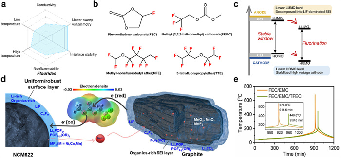
Fluorides are another free radical bursting solvent that is inherently electrochemically and chemically stable (Fig. 3a). Fluorides are a category of halogenated flame retardants that decompose at high temperatures to produce hydrogen halide (HX). This interacts with HO· to impede the chain reaction of combustion, while its decomposition products also facilitate carbonization of the substrate material. It is notable that other halogenated flame retardants, such as bromines and chlorines, have received minimal attention from researchers due to their adverse environmental impact and comparatively lower flame retardant efficiency compared to fluorides. As shown in Fig. 4b, common fluorides include fluorinated carbonates (such as fluoroethylene carbonate (FEC), methyl(2,2,2-trifluoroethyl)carbonate (FEMC)) and fluorinated ethers (such as methyl-nonafluorobutyl ether (MFE), 1,1,2,2-tetrauoroethyl-2,2,3,3-tetrauoropropyl ether (TTE)). The specific physical properties are shown in Table 3. This section will provide an overview of fluorides in terms of their thermal stability, interfacial stability and their role in electrolytes. The aim is to provide a relevant theoretical basis and inspiration for the design of flame-retardant electrolytes.
 DownLoad:
CSV
DownLoad:
CSV
| Solvents | Boiling point (℃) | Flash point (℃) |
| FEC | 249.5 | 130 |
| FEMC | 74.2 ± 40 | – |
| MFE | 60 | – |
| TTE | 92 | 27.5 |
Although fluorides have a weaker ability to trap H and OH radicals than phosphates, they exhibit higher thermal stability towards fully charged cathodes. Zhang et al. [65] employed differential scanning calorimetry (DSC) to assess the heat release of a range of compounds, including common carbonates, ethers, sulfones, phosphates, and fluorides, in combination with NCM811. The fluorides exhibited relatively lower heat release (<200 J/g) and higher onset/peak temperatures (>200 ℃) in general. On the contrary, the methyl-containing TMP were not thermally stable enough when combined with a fully charged cathode, resulting in significant heat release (425.6 J/g). Song et al. [66] also reached the same conclusion. This indicates that the formation of a uniform and stable unique interface by fluorides has a beneficial effect on the stability of the cathodes, as well as reducing their exothermic temperature and heat release during TR.
The most significant contribution of fluorides to the safety is the formation of a robust, uniform and dense interfacial film at the cathode and anode interfaces, particularly under high voltage conditions (Fig. 4c). Firstly, the strong electron-absorbing ability of elemental fluorine lowered the LUMO energy level of fluorides to preferentially decompose into LiF-dominated SEIs with high stability [67] and Young’s modulus [68], and lowered the HOMO energy level to promote stable operation of high-voltage cathodes [47]. Song et al. [66] reported a nonflammable electrolyte consisting of methyl(2,2,2-trifluoroethyl)carbonate (FEMC), which was found to form a organics-rich surface layer on the cathode of the NCM622 and graphite anode, effectively solving the metal dissolution, cracking, and structural degradation problems of the NCM622 cathode at high voltage of 4.5 V (Fig. 4d). Secondly, fluorides with weak polarization and low intermolecular interaction forces can induce lithium anion-dominated interfacial chemistry to stabilize the battery operation. Xiao et al. [69] designed a non-flammable electrolyte consisting of FEC/bis(2,2,2-trifluoroethyl)carbonate (BTC). The introduction of the -F group weakened the solvent binding to Li+, so that more anions entered the solvated structure of Li+, reducing the desolvation energy of Li+ and forming a stable interface. Compared to the EC/DEC-based electrolyte, no significant lithium dendrites were observed after 2 h of lithium deposition on copper foil, and a lithium deposition thickness close to the theoretical value (10.8 mm) was obtained. And the Li||NCM811 cell achieved >100 cycles at ultra-high cut-off voltages of 4.7 V and 4.8 V. Thus, the contribution of fluorides to the interfacial stability of batteries is remarkable, but how to rationally design the molecular structure of fluorides to balance their functionality and environmental sustainability has been troubling researchers.
Combining the properties of different fluorides to construct a reasonable solvation structure is an important means to achieve battery level safety. The roles of fluorinated carbonates and fluorinated ethers in the electrolyte are typically distinct, depending on the number of substitutions of the fluorine atom. In comparison to EC, fluorinated carbonates exhibit reduced dielectric constants and DN values [70], act as weak coordination solvents, and are frequently employed in the construction of weakly solvated electrolytes. Zhang et al. [65] evaluated the binding energies of EMC, FEC, and 2,2,2-trifluoroethyl ethyl carbonate (TFEC) with Li+, and TFEC exhibited the lowest binding energy (−1.51 eV). As a result, the TFEC-based electrolyte showed a weakened interaction of Li+ with the solvent but an enhanced interaction with the anion. This electrolyte greatly improves the safety of commercial Gr||NCM523 pouch batteries under abusive conditions such as nail penetration (Fig. 4e), package damage, and exposure to open flame. In contrast, highly fluorinated ethers have low surface tension and low viscosity and usually act as diluents in electrolytes. The diluents do not alter the original solvated structure, but appear more at the periphery of the solvated sheath layer, participating in the construction of the SEI and CEI while modulating the physicochemical properties of the electrolyte [71-73]. Ren et al. [74] reported on a TTE-based localized highly concentrated electrolyte and provide insight into the solvated structure of this electrolyte system. It was found that the TTE diluent does not interfere with the strong interactions between FSI- and Li+ in the highly concentrated electrolyte and leads to more FSI- anions into the inner solvated sheath layer. Under the requirements of high voltage, high loaded cathode, and thin lithium anode, the capacity retention of TTE-based lithium metal battery was >80% for 150 cycles, while the baseline electrolyte lost all capacity for 20 cycles. Fluorides have been shown to enhance the cycling performance and safety of batteries to varying degrees, both as the primary solvent and as a diluent. However, the precise relationship between the molecular structure and the electrolyte function, as well as the specific mechanisms involved in the formation of CEI and SEI, remain unknown.
In summary, fluorides as flame-retardant solvents can capture free radicals generated in combustion, while reducing the heat of reaction with the electrodes. They can not only form LiF-rich interfacial layers, but also act as diluents or weak coordination solvents to build more stable solvated structures, which widens the cycle life and applicability of the battery. However, highly fluorinated solvents cause cost and environmental problems, so molecular design with low fluorine content is needed to balance the safety, cost and performance of LIBs. The relevant literature reports are shown in Table 2 [65,66,75-78].
Fluorinated phosphates with two flame-retardant elements (F, P) and fluorinated phosphonitriles with three elements (F, N, P) have the synergistic flame-retardant effect, which are more efficient flame-retardant solvents (Fig. 5a). They enhance the free radical-destroying ability of the phosphates while maintaining the advantages of the thermal and electrochemical stability of fluorides. Common fluorinated phosphates include linear fluorophosphates (such as (2,2,2-trifluoroethyl)diethyl phosphate (TDP), bis(2,2,2-trifluoroethyl)methylphosphate (BMP), tris(2,2,2-trifluoroethyl)phosphate (TFP)) and cyclic fluorophosphates (such as 2-ethoxy-1,3,2-dioxaphospholane 2-oxide (TFEP)), and fluorophosphonitriles (such as hexafluorocyclotriphosphazene (HFPN), (ethoxy)pentafluorocyclotriphosphazene (PFPN), pentafluoro(phenoxy)cyclotriphosphazene (FPPN)), as shown in Fig. 5b. The following section provides an overview of the structures of fluorinated phosphates and fluorinated phosphonitriles, their effect on interfacial stability and achieving battery-level safety, respectively.
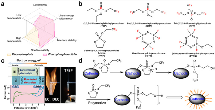
The number and position of fluorine substitutions exert a significant influence on the flame retardancy and properties of fluorinated phosphonates and fluorinated phosphonitriles. Although the flame retardancy of each solvent is slightly different depending on its structure, the basic order is as follows: fluorinated linear phosphates < fluorinated cyclic phosphates < fluorinated phosphonitriles. Xu et al. [79,80] systematically evaluated the effect of the degree of fluorination of TEP (TDP, BMP, and TFP) on the physical properties, flammability, and electrochemical stability, they found that the higher the degree of alkyl fluorination, the higher the flame-retardant efficiency. The β-position substitution of TFP perfectly achieves the balance between electrolyte non-flammability and battery performance [81], and is widely used in the research of high safety electrolyte systems (Fig. 5c) [82-85]. Notably, the fluorinated substitution of more branched chains, although is effective in improving the flame-retardant efficiency, brought about a thicker SEI layer and greater interfacial transfer impedance [86]. This conclusion also applies to fluorinated cyclic phosphate esters [87,88]. However, substitution of high F-element content shows the opposite result in phosphonitriles. The simplest hexafluorocyclic triphospho nitrile HFPN with a boiling point of only 52 ℃ cannot achieve the safety of LIB. Therefore, researchers have developed ether-modified fluorophosphonitriles based on HFPN, which realize the combined advantages of lithium metal anode compatibility and high voltage tolerance. Feng et al. [89] found that adding 12 wt% FPPN to the carbonate electrolyte provided effective overcharge protection for LNMO||Li batteries. In the overcharge test, the charge voltage of the battery with this electrolyte was stable at 5.05 V even after 200% of the overcharge capacity. Fluorinated phosphates and phosphonitriles have improved flame retardancy and thermal stability, and the F substitution at the β-C position is able to achieve a good balance between high oxidative stability, good solubility and conductivity. However, the complex preparation process and high manufacturing cost of these emerging molecules have hindered their development.
The multi-element synergy of fluorinated phosphates and fluorinated phosphonitriles exhibits unique advantages in terms of interfacial stability and safety. Zheng et al. [88] investigated the mechanism by which the fluorinated phosphate TFEP stabilizes the operation of a 4.7 V battery. When TFEP was attacked by the nucleophilic attack of oxygen atoms on the metal surface, a ring-opening reaction occurred to eventually form a polyphosphate-rich cathode electrolyte interface (CEI) layer (Fig. 5d). The CEI layer served to inhibit the oxidative decomposition of the electrolyte, prevent the dissolution of the transition metal, and reduce the side reaction between the imide salt and the Al. Kim et al. [90] added 5% fluorinated phosphonitrile HFNPN to carbonate electrolyte and achieved 400 stable cycles at 0.5 C multiplication rate for 5 V grade Li||LNMO battery with 86% discharge capacity retention, which is significantly improved compared with 58% in the pristine electrolyte. This was achieved thanks to the stable ion-conducting interfacial layer and the fact that HFEPN effectively eliminated HF, significantly reducing the dissolution of Ni and Mn in LNMO. The ring-opening effect of cyclic phosphates and the strong electron-absorbing effect of F together give fluorinated phosphates and fluorinated phosphonitriles super-high interfacial stability, but due to the cost and the existing manufacturing technology, the mechanism of these flame-retardant solvents in the electrolyte and the interfacial mechanism of formation still need to be more in-depth study.
If the electrolyte can be custom-designed based on the basic properties of fluorinated phosphates and fluorinated phosphonitriles, it is expected that battery-level safety can be achieved, and even the occurrence of thermal runaway can be controlled. It is generally accepted that conventional phosphates are high coordination number solvents, which are not favorable for the formation of ion-solvent-coordinated structures. Therefore, Chen et al. [84] constructed a weakly solvated electrolyte using low coordination number FEMC together with TFP, and FEMC reduced the coordination of P=O (TFP) with Li+ and enhanced the coordination of PF6- with Li+. The graphite||NMC811 pouch cell achieved high cycling stability (93% capacity retention for 300 cycles) and was successfully validated by spike test. On the other hand, fluorinated phosphonitriles have a rather high viscosity, which considerably limits their ion transport kinetics. Especially the bulky phosphonitrile molecules are generally used only as additives (<10 vol%) [91-93]. Liu et al. [94] were surprised to find a special coordination effect of ethoxy(pentafluoro)cyclic triphosphonitrile (PFPN) with Li+. The N and O atoms of PFPN achieved stable coordination with Li+ and the spatial site resistance weakened the coordination ability of conventional solvents (e.g., dimethyl ether (DME)), increasing the chance of Li+-anion coordination. The NMC811 full cell has a capacity retention rate of 84.1% after 150 cycles at the ultra-high voltage of 4.6 V, while the capacity of the base sample declines significantly after 100 cycles. Although fluorinated phosphonitriles and fluorinated phosphates can be used as additives for flame retardant purposes, small amounts of these additives are not sufficient to achieve battery-grade safety. It is more worthwhile to understand the mechanism of each molecular structure in the electrolyte and introduce them into the solvated structure to maintain the safety of the battery for a long period of time and delay the thermal runaway of the battery.
Multi-element synergistic fluorophosphates and fluorophosphonitriles are more effective than single-element flame retardants, and show significant compatibility with electrodes, with relatively small degree of impact on batteries as additives. However, the realization of battery-level safety requires an in-depth understanding of the oxidative stability, ion transport capacity and coordination ability of these molecules, as well as a rational electrolyte structure design. But there are fewer studies in this field at present. The latest relevant studies have been displayed in Table 2 [84,95-99].
Ionic liquids (ILs) are novel solvents consisting only of anions and cations with a wide electrochemical window and high thermal stability [100]. The low flammability of these solvents is due to the strong interactions between the ions [101]. In LIBs, the lithium salts are usually used as the coordinating anion, and the cations are imidazolium, pyrrolidinium, piperidinium, phosphonium, and so on. In this section we analyse the thermal stability of ILs, then point out their shortcomings as solvents for lithium-ion battery electrolytes, and finally comment on the existing strategies and give our own views.
ILs possess excellent thermal stability, so their decomposition properties at elevated temperatures have always been a concern. Huddleston et al. [102] investigated the thermal decomposition properties of ILs consisting of 1‑butyl‑3-methylimidazole (C4mim), 1-hexyl-3-methylimidazole (C6mim), and 1-octyl-3-methylimidazole (C8mim) as cations with BF4-, Cl-, I-, PF6-, and Tf2N- as anions. For most of the ILs, their thermal decomposition temperatures are above 250 ℃, with [C4mim]Cl being the lowest at 254 ℃ and [C4mim][Tf2N] reaching 439 ℃. It has been demonstrated that the type of anion is the primary factor influencing the thermal stability of ILs.
However, pure ILs exhibit high viscosity and low conductivity at room temperature, and most of them cannot be decomposed to form a stable SEI film [103]. The conventional approach is to combine the ionic liquid with a low-viscosity organic solvent [104,105]. Wang et al. [105] designed intrinsically nonflammable electrolytes by adding TEP to N-methyl-N-propyl-pyrrolidinium bis(trifluo-romethyl sulfonyl)imide [Pyr13][TFSI] ionic liquid. In this electrolyte, the Pyr13+ cation exerts an electrostatic shielding effect, while the TFSI- and DFOB- anions can participate in the solvation structure of Li+ improving the stability of the nickel-rich cathode and inhibiting the growth of Li dendrites. 2.2 Ah lithium-metal flexible packs were used without any smoke or fire during nail penetration. It can thus be seen that the incorporation of organic solvents and the creation of solvated structures are crucial strategies for ensuring the stable operation of ILs in batteries.
ILs as a refractory organic solvent are remarkable for the improvement of electrolyte thermal decomposition temperature and flash point, but they are limited by high viscosity and high cost. Combining them with organic solvents can improve battery performance, but specific solvent screening and solvation design methods still need to be investigated urgently.
Deep eutectic solvents (DESs) are also flame-retardant solvents with low volatility, which is similar to ILs, but DESs are cheaper to prepare and less toxic [106]. Generally, DES is a liquid medium obtained by mixing two or more self-consolidating components. Its melting point is lower than that of the individual components, and the basic principle is shown in Figs. 6a and b [107]. Currently, the deep eutectic electrolytes (DEEs) used in LIBs are mainly nitriles and amides, such as Urea-LiTFSI [108], N-methylacetamido-LiTFSI [109], SN-LiFSI [110]. In the following, the thermal stability characteristics of DESs will be presented, and then the interfacial stability issues when they are used as electrolytes will be discussed.
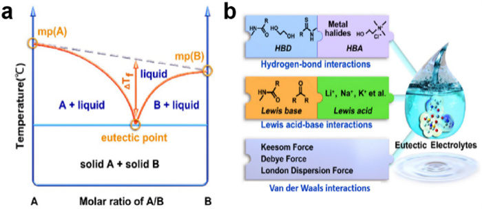
The thermal stability of DESs is closely related to the type and proportion of components. In general, DESs are formed by three main types of interactions, namely hydrogen bonds, Lewis acids and bases, and van der Waals forces [107]. They require solubility between the different components and good mobility at room temperature. The strength of these interactions can be modified by adjusting the solvent composition and mixing ratio. Ghaedi et al. [111] investigated the thermal decomposition temperatures of DESs with varying molar ratios. They employed allyltriphenylphosphonium bromide as the hydrogen bond acceptor (HBA) and diethylene glycol and triethylene glycol as the hydrogen bond donors (HBD). It was observed that the thermal stability of the DESs increased in conjunction with the rise in HBA content. Furthermore, the onset temperatures (Tonset) of thermal degradation for all the DESs were recorded to be above 300 ℃. In addition, the thermal stability of DESs is related to the properties of each individual component itself [112]. Therefore, DESs for high safety LIBs need to consider the thermal stability of the components and the strength of the interaction between the components, as well as whether they meet the basic requirements foruse as an electrolyte, such as conductivity and viscosity.
In DEEs, the deposition potential and the corresponding deposition sequence between the anion of the metal salt and the organic ligand affect the composition and stability of the SEI and CEI. Hu et al. [113] introduced two lithium salts (LiDFOB and LiTFSI) into succinonitrile (SN) in order to form a double anion DEE dominated by hydrogen bonding interactions. In the eutectic system, TFSI- and DFOB- can preferentially SN molecules to react chemically with lithium metal, which ensures a stable SEI containing LiF, Li3 N, LixBFyOz and sulphides on the lithium anode. It allowed the Li||Li symmetric batteries to be cycled stably for >10,000 h. However, free HBD molecules may react with the lithium anode resulting in a large interfacial impedance, therefore, it is feasible to improve the battery performance by using additives to form a stable SEI. Liang et al. [114] modulated the solvated structure of DEE consisting of LiTFSI/N-methylacetamide (NMAC) by LiNO3. Simulations showed that the interaction of NMAC with Li+ was stronger than that of NO3-, which increased the solubility of LiNO3 in the DEE and enhanced the interaction of TFSI- with Li+. The Li||NCM622 cell reached 84% capacity retention after 600 cycles at 0.5 C, which was much higher than that of conventional carbonate electrolyte capacity retention (56%). Therefore, allowing preferential deposition of metal salt anions and reduction of free HBD molecules can improve the electrochemical performance and interfacial stability of DEEs. DES as a hard-to-volatilise green solvent has a promising application in LIB safety applications. However, its large size characteristics and relatively free volume of ions can lead to undesired viscosity and ionic conductivity, and the free HBD can side-react with lithium metal anode. Therefore, the coming work should be devoted to further selecting suitable DES components, especially introducing flame-retardant groups, so as to develop green, safe, and high-performance DEEs suitable for LIBs. Several relevant studies have been summarized in Table 2 [113-116].
Comprehensive safety testing is essential for the rational design of flame-retardant electrolytes and performance evaluation for practical applications. The thermal safety performance of the electrolyte itself is the foundation for realizing high safety batteries, which can reduce the possibility of thermal runaway, short-circuit and other safety risks from the source. As the battery is the place where thermal runaway occurs, it is also necessary to evaluate the safety of the whole battery system. Therefore, this section outlines the relevant safety test methods from the material level and battery level respectively (Fig. 7).
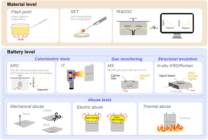
In the design process of LIBs, the electrolyte is the ‘short board’ that determines the safety of LIBs. And it is essential to evaluate the safety of each component. It is therefore essential to conduct relevant safety tests at the material level, with a particular focus on the electrolyte’s flammability, self-extinguishing properties and thermal stability. The details are as follows:
Flash point (FP) is a physical property that describes the lowest temperature at which a liquid is ignited at standard atmospheric pressure, and reflects the ease with which the material itself can be ignited. According to the Occupational Safety and Health Administration (OSHA) and the National Fire Protection Agency (NFPA), a liquid is defined as flammable if the FP is < 38 ℃, and as combustible when the flash point is between 38 ℃ and 93 ℃.
Self-extinguishing time (SET) indicates the burning time of the liquid after ignition. The self-extinguishing capability of the electrolyte is generally assessed by observing whether the target electrolyte can extinguish the flame. It is not possible to make qualitative comparisons between the different articles due to the differences in ignition temperatures and test methods employed [117]. Xu et al. [118] recommend the use of small ball wicks soaked in 0.05–0.1 g electrolyte to minimize the exposure of the electrolyte to air and avoid the effects of wettability. They also divided the electrolyte into three categories: (1) SET < 6 s/g, non-combustible; (2) SET > 20 s/g, flammable; (3) 6 s/g < SET < 20 s/g, flame-retardant.
Thermogravimetric analysis (TA) and differential scanning calorimetry (DSC), which show the changes in sample weight and heat flow with increasing temperature, are commonly used to respond to differences in the thermal stability of different electrolyte systems and to explain the corresponding thermal decomposition mechanisms. Specifically, by comparing the onset apparent weight loss temperatures [119], the onset exothermic peaks, and the amount of exothermic heat at a given stage for different systems [65], higher thermally stable samples will be quickly screened out, which is an important tool for the optimisation of our formulations. In particular, they can also provide data to support the pyrolysis behaviour of the electrolyte system. For example, Mu et al. [120] performed TA and DSC tests on three systems, LE, GPE and polymer matrix, respectively, and found that the thermal behaviour was dominated by LE degradation in stage Ⅲ of the fitted curves, while the polymer matrix was dominant in stages Ⅳ and Ⅴ.
Unlike the material level tests, the battery level safety tests can intuitively reflect the safety performance of the battery in practical application, including calorimetric tests, gas monitoring, structural evolution and abuse tests under overcharge, overdischarge, short-circuit and high-temperature conditions for the whole battery system. The details are as follows:
Accelerated scanning calorimetry (ARC) and infrared thermography (IT) are used to monitor thermal changes in the battery. ARC is employed to forecast the potential TR behavior of a sample during its actual utilization by monitoring its temperature alteration in an adiabatic setting. The ARC test is highly sensitive and can synchronously obtain a variety of data, such as the dynamic curves of temperature, resistance, voltage, and resistance over time, and the data analysis to obtain the initial decomposition temperature, exothermic rate, heat of reaction, activation energy, and pressure, which is an important tool used by the researchers to predict the battery’s TR mechanism [121]. In addition to evaluating the basic thermal characterization data, Cui et al. [122] investigated the crosstalk behavior of the gaseous by-products by means of a self-designed two-sphere crosstalk experimental setup, which demonstrated that cathode crosstalk affected the battery more than the anode. IT uses infrared radiation to detect and image the temperature distribution on the surface of an object, which is a non-destructive testing technique. Researchers usually compare the temperature changes inside LIBs of different systems under conditions such as fast charging [62], pinning [123], thermal abuse [64] and so on, to demonstrate the safety of flame-retardant electrolytes.
In-situ X-ray diffraction spectroscopy/Raman spectroscopy (in-situ XRD/Roman) are used to monitor the structural evolution of batteries during charging and discharging. Similarly, varying the charging/discharging interval [97] and environmental temperature [124] allowed access to the reaction mechanisms under different conditions. For example, Tan et al. [97] found a symmetric distribution of in situ XRD contours during one charge/discharge cycle, verifying the high reversibility of phosphonitrile molecules to graphite anode. Li et al. [125] examined the thermal stability of the near-surface structure of NCM materials using in-situ Raman. By comparing the spectral shifts at different stages, it was found that the thermal stability was significantly affected by the electrolyte composition, such as dehydrogenation, adsorption, oxidation of carbonate solvents, and decomposition of lithium salts, which is an important guideline for enhancing the thermal stability of high-Ni NCM materials.
Differential electrochemical mass spectrometry (DEMS) is a technique for detecting changes in gaseous reactants or products during electrochemical reactions. It allows for the in situ quantitative and qualitative detection of chemicals, including gaseous or volatile electrochemical reactants, reaction intermediates, and products derived from the main cell materials, during electrochemical cell cycling [126]. The specific gas species can be determined from the mass/charge ratio (m/z) and intensity of the material. For example, Liu et al. followed the gas production in graphite anodes during the decomposition of the reducing electrolyte and subsequent SEI production, and speculated on the mechanism of anode SEI film formation [127].
Abuse testing evaluates the safety of lithium-ion battery systems under abusive conditions, including mechanical abuse, electrical abuse, and thermal abuse. Mechanical abuse includes test items such as puncture, shear, and bending. Chen et al. [84] demonstrated the high safety of the designed electrolyte by performing a pinning test on a 5 Ah graphite||NMC811 pouch cell. Electrical abuse refers to overcharge and overdischarge testing of batteries. Thermal runaway characteristics (temperature, gas release, capacity degradation, etc.) can be obtained by charging to a specific state of charge (SOC > 100%) or by overdischarging to a specific potential (0–2 V) [4]. Thermal abuse refers to abuse testing of battery systems that are overused or exposed to high temperatures. In a high temperature environment, the internal reaction of the battery is intensified, leading to an increase in the internal resistance of the battery, a decrease in capacity, and even causing safety problems such as battery expansion, leakage, and explosion. Thermal abuse reacts to the battery’s tolerance at high temperatures [128].
From the above, it can be found that material level tests can quickly and efficiently obtain the intrinsic thermal stability characteristics of the electrolyte, but they cannot reflect the stability and compatibility of the electrolyte in the battery, and the existing test methods lack a unified test standard. Battery level tests intuitively respond to the safety condition of the battery in a specific situation and are flexible and tunable, but these tests are generally long and costly and require extensive experimental validation. Consequently, the combination of two or more characterization modalities for integrated assessment is a future trend, while there is in urgent need to develop efficient and comprehensive characterization systems.
In this review, it is found that the electrolyte, which plays a key role in heat accumulation, is a key factor in reducing the risk of thermal runaway and cutting off heat release. Considering that the design of the electrolyte is a systematic project, we have analyzed the thermal, electrochemical and interfacial stability of several common flame-retardant solvents to achieve intrinsic non-flammability and meet the requirements of battery level safety. Considering the shortcomings of existing research, suggestions are shown as follow:
(1) The thermal runaway process of specific battery systems with novel flame-retardant electrolytes should be investigated. Although several types of flame-retardant solvents mentioned in this paper can increase the T1 and T2 temperatures, which can delay the thermal runaway to a certain extent. However, once the threshold temperature is reached, the thermal decomposition characteristics of the flame-retardant electrolyte at elevated temperatures and the specific thermal runaway evolution are unknown. The thermal hazard characteristics of the system also need to be evaluated.
(2) The future should be devoted to the development of flame-retardant electrolytes that can improve battery safety and have comparable electrochemical performance. While existing flame-retardant solvents can enhance the safety of the system, their roles and mechanisms in the electrolyte remain unclear, resulting in poor cycling performance of the battery. Based on the functional properties of flame-retardant solvents, the design of a reasonable and stable solvation structure to promote the continuous optimization of battery performance and the continuous improvement of battery safety is the future development direction.
(3) New safety characterization techniques for electrolyte need to be developed. The safety assessment of flame-retardant solvents should not be limited to the thermal decomposition temperature and non-ignition, but should also focus on the rate of heat production and reactivity with electrode materials. Therefore, more new characterization techniques are needed to systematically analyze the safety of systems at the electrolyte level and at the battery level. For example, detection of reactive oxygen content and characterization of the thermal stability of the interfacial phase of the electrolyte.
Yaxuan Fu: Writing – review & editing, Writing – original draft, Investigation, Data curation. Xiaozhi Jiang: Investigation, Data curation. Chenyang Shi: Investigation. Long Chen: Investigation. Zhendong Yang: Data curation. Mengran Wang: Writing – review & editing. Bo Hong: Formal analysis, Conceptualization. Faping Zhong: Writing – review & editing. Yanqing Lai: Validation.
We gratefully acknowledge the National Natural Science Foundation of China (No. 52174287), Central South University Research Programme of Advanced Interdisciplinary Studies (No. 2023QYJC005), Young Elite Scientists Sponsorship Program by CAST (No. 2023QNRC001), the Natural Science Foundation of Hunan Province (No. 2024JJ5425), the Science and Technology Innovation Program of Hunan Province (No. 2023RC3054).
The authors declare that they have no known competing financial interests or personal relationships that could have appeared to influence the work reported in this paper.
K.Y. Park, J.M. Lim, N.S. Luu, et al., Adv. Energy Mater. 10 (2020) 2001216. doi: 10.1002/aenm.202001216
L.H. Zhao, N.R. Sottos, Adv. Energy Mater. 11 (2021) 2003139. doi: 10.1002/aenm.202003139
Y. Wang, X.N. Feng, W.S. Huang, et al., Adv. Energy Mater. 13 (2023) 2203841. doi: 10.1002/aenm.202203841
Z. Ye, J.Y. Li, Z.J. Li, J. Mater. Chem. A 11 (2023) 15576–15599. doi: 10.1039/d3ta01951a
D. Chen, Y. Liu, C. Feng, Electron 1 (2023) e1. doi: 10.1002/elt2.1
R. Razaq, M.M.U. Din, D.R. Småbråten, et al., Adv. Energy Mater. 14 (2024) 2302897. doi: 10.1002/aenm.202302897
B. Song, L. Su, X. Liu, et al., Electron 1 (2023) e13. doi: 10.1002/elt2.13
X.N. Feng, M.G. Ouyang, X. Liu, et al., Energy Storage Mater. 10 (2018) 246–267. doi: 10.1016/j.ensm.2017.05.013
K. Xu, Chem. Rev. 114 (2014) 11503–11618. doi: 10.1021/cr500003w
L. Xia, L.P. Yu, D. Hu, et al., Acta Chim. Sin. 75 (2017) 1183–1195. doi: 10.6023/A17060284
R. Pacios, A. Villaverde, M. Martínez, et al., Adv. Energy Mater. 13 (2023) 2301018. doi: 10.1002/aenm.202301018
M.C. Long, T. Wang, P.H. Duan, et al., J. Energy Chem. 65 (2022) 9–18. doi: 10.1016/j.jechem.2021.05.027
V. Ramar, C. Pszolla, M. Rapp, et al., J. Electrochem. 167 (2020) 070521. doi: 10.1149/1945-7111/ab7119
J. Xie, Y.C. Lu, Adv. Mater. (2024) 2312451.
M.C. Liu, Q.S. Liu, Y.Z. Quan, et al., Chin. Chem. Lett. 35 (2024) 109123. doi: 10.1016/j.cclet.2023.109123
Y.Z. Quan, Q.S. Liu, M.C. Liu, et al., J. Energy Chem. 84 (2023) 374–384. doi: 10.1016/j.jechem.2023.05.041
Q.S. Liu, Y.Z. Quan, M.C. Liu, et al., J. Energy Chem. 83 (2023) 239–246. doi: 10.1016/j.jechem.2023.04.021
X.N. Feng, S.Q. Zheng, D.S. Ren, et al., Appl. Energy 246 (2019) 53–64. doi: 10.1016/j.apenergy.2019.04.009
F.F. Zhai, Q. Zhou, Z.L. Lv, et al., EnergyChem 4 (2022) 100082. doi: 10.1016/j.enchem.2022.100082
J.W. Wen, Y. Yu, C.H. Chen, Mater. Express 2 (2012) 197–212. doi: 10.1166/mex.2012.1075
H. Ishikawa, O. Mendoza, Y. Sone, et al., J. Power Sources 198 (2012) 236–242. doi: 10.1016/j.jpowsour.2011.09.067
C.S. Xu, X.N. Feng, W.S. Huang, et al., J. Energy Storage 31 (2020) 101670. doi: 10.1016/j.est.2020.101670
J.L. Liu, Z.H. Huang, J.H. Sun, et al., J. Power Sources 526 (2022) 231136. doi: 10.1016/j.jpowsour.2022.231136
P.F. Huang, C.X. Yao, B.B. Mao, et al., Energy 213 (2020) 119082. doi: 10.1016/j.energy.2020.119082
Y.S. Duh, Y.J. Sun, X. Lin, et al., J. Energy Storage 41 (2021) 102888. doi: 10.1016/j.est.2021.102888
D.S. Ren, X.N. Feng, L.G. Lu, et al., Appl. Energy 250 (2019) 323–332. doi: 10.1016/j.apenergy.2019.05.015
X. Liu, D.S. Ren, H.J. Hsu, et al., Joule 2 (2018) 2047–2064. doi: 10.1016/j.joule.2018.06.015
L. Huang, G.J. Xu, X.F. Du, et al., Adv. Sci. 8 (2021) 2100676. doi: 10.1002/advs.202100676
X.N. Feng, X.M. He, M.G. Ouyang, et al., J. Electrochem. 165 (2018) A3748–A3765. doi: 10.1149/2.0311816jes
H. Li, Q. Duan, C. Zhao, et al., J. Hazard. Mater. 375 (2019) 241–254. doi: 10.1201/9780429026577-22
X. Feng, S. Zheng, D. Ren, et al., Appl. Energy 246 (2019) 53–64. doi: 10.1016/j.apenergy.2019.04.009
S. Abada, G. Marlair, A. Lecocq, et al., J. Power Sources 306 (2016) 178–192. doi: 10.1016/j.jpowsour.2015.11.100
K. Zhang, G.H. Lee, M. Park, et al., Adv. Energy Mater. 6 (2016) 1600811. doi: 10.1002/aenm.201600811
M.N. Richard, J.R. Dahn, J. Power Sources 83 (1999) 71–74. doi: 10.1016/S0378-7753(99)00260-8
S.E. Sloop, J.K. Pugh, S. Wang, et al., Electrochem. Solid-state Lett. 4 (2001) A42–A44. doi: 10.1149/1.1353158
T. Kawamura, S. Okada, J. Yamaki, J. Power Sources 156 (2006) 547–554. doi: 10.1016/j.jpowsour.2005.05.084
D.D. MacNeil, J.R. Dahn, J. Electrochem. Soc. 148 (2001) A1205–A1210. doi: 10.1149/1.1407245
R. Spotnitz, J. Franklin, J. Power Sources 113 (2003) 81–100. doi: 10.1016/S0378-7753(02)00488-3
Q. Wang, J. Sun, C. Chen, et al., Rare Metals 25 (2006) 94–99. doi: 10.1016/S1001-0521(07)60052-7
J.N. Ye, H.D. Chen, Q.S. Wang, et al., Appl. Energy 182 (2016) 464–474. doi: 10.1016/j.apenergy.2016.08.124
Y. Wang, X.N. Feng, Y. Peng, et al., Joule 6 (2022) 2810–2820. doi: 10.1016/j.joule.2022.10.010
Y. Wang, D.S. Ren, X.N. Feng, et al., Appl. Energy 306 (2022) 117943. doi: 10.1016/j.apenergy.2021.117943
Y. Wu, X.N. Feng, X. Liu, et al., Energy Storage Mater. 43 (2021) 248–257. doi: 10.3390/act10100248
Y. Li, X. Liu, L. Wang, et al., Nano Energy 85 (2021) 105878. doi: 10.1016/j.nanoen.2021.105878
G.R. Zhu, Q. Zhang, Q.S. Liu, et al., Nat. Commun. 14 (2023) 4617. doi: 10.1038/s41467-023-40394-8
M.C. Long, G. Wu, X.L. Wang, et al., Energy Storage Mater. 53 (2022) 62–71. doi: 10.1016/j.ensm.2022.08.044
K.R. Deng, Q.G. Zeng, D. Wang, et al., Energy Storage Mater. 32 (2020) 425–447. doi: 10.1016/j.ensm.2020.07.018
K. Chen, X.H. Shen, L.B. Luo, et al., Angew. Chem. Int. Ed. 62 (2023) e202312373. doi: 10.1002/anie.202312373
H.R. Cheng, Z. Ma, P. Kumar, et al., ACS Energy Lett. 9 (2024) 1604–1616. doi: 10.1021/acsenergylett.3c02789
X.M. Wang, E. Yasukawa, S. Kasuya, J. Electrochem. 148 (2001) A1066–A1071. doi: 10.1149/1.1397774
H. Nakagawa, M. Ochida, Y. Domi, et al., J. Power Sources 212 (2012) 148–153. doi: 10.1016/j.jpowsour.2012.04.013
D.W. Zhang, H.W. Fu, X.M. Ma, et al., Angew. Chem. Int. Ed. 63 (2024) e202405153. doi: 10.1002/anie.202405153
H. Ota, A. Kominato, W.J. Chun, et al., J. Power Sources 119 (2003) 393–398.
K.C. Hogstroem, H. Lundgren, S. Wilken, et al., J. Power Sources 256 (2014) 430–439. doi: 10.1016/j.jpowsour.2014.01.022
D. Gao, J.B. Xu, M. Lin, et al., RSC Adv. 5 (2015) 17566–17571. doi: 10.1039/C4RA15899G
J.K. Feng, Y.L. Cao, X.P. Ai, et al., Electrochim. Acta 53 (2008) 8265–8268. doi: 10.1016/j.electacta.2008.05.024
L.H. Jiang, C. Liang, H. Li, et al., ACS Appl. Energy Mater. 3 (2020) 1719–1729. doi: 10.1021/acsaem.9b02188
X.M. Wang, C. Yamada, H. Naito, et al., J. Electrochem. 153 (2006) A135–A139. doi: 10.1149/1.2136078
B. Qiu, L.Z. Xie, K.Y. Liang, et al., Appl. Surf. Sci. 612 (2023) 155936. doi: 10.1016/j.apsusc.2022.155936
H. Su, H.K. Zhang, Z.F. Chen, et al., Chin. Chem. Lett. 34 (2023) 108640. doi: 10.1016/j.cclet.2023.108640
Z. Zeng, V. Murugesan, K.S. Han, et al., Nat. Energy 3 (2018) 674–681. doi: 10.1038/s41560-018-0196-y
Z. Deng, Y. Jia, Y. Deng, et al., J. Energy Chem. 96 (2024) 282–290. doi: 10.1016/j.jechem.2024.04.041
S. Chen, J. Zheng, L. Yu, et al., Joule 2 (2018) 1548–1558. doi: 10.1016/j.joule.2018.05.002
C. Liao, L. Han, W. Wang, et al., Adv. Funct. Mater. 33 (2023) 2212605. doi: 10.1002/adfm.202212605
S.C. Zhang, S.Y. Li, X.Y. Wang, et al., Nano Energy 114 (2023) 108639. doi: 10.1016/j.nanoen.2023.108639
G.J. Chung, J. Han, S.W. Song, ACS Appl. Mater. Inter. 12 (2020) 42868–42879. doi: 10.1021/acsami.0c12702
X.L. Fan, L. Chen, O. Borodin, et al., Nat. Nanotechnol. 13 (2018) 715–722. doi: 10.1038/s41565-018-0183-2
R. Pathak, K. Chen, A. Gurung, et al., Nat. Commun. 11 (2020) 93. doi: 10.1038/s41467-019-13774-2
P.T. Xiao, Y. Zhao, Z.H. Piao, et al., Energy Environ. Sci. 15 (2022) 2435–2444. doi: 10.1039/d1ee02959b
Z. Wang, B. Zhang, Energy Mater. Devices 1 (2023) 9370003. doi: 10.26599/emd.2023.9370003
S.R. Chen, J.M. Zheng, D.H. Mei, et al., Adv. Mater. 30 (2018) 1706102. doi: 10.1002/adma.201706102
S.P. Beltran, X. Cao, J.G. Zhang, et al., Chem. Mater. 32 (2020) 5973–5984. doi: 10.1021/acs.chemmater.0c00987
H. Jia, Y.B. Xu, X.H. Zhang, et al., Angew. Chem. Int. Ed. 60 (2021) 12999–13006. doi: 10.1002/anie.202102403
X.D. Ren, L.F. Zou, X. Cao, et al., Joule 3 (2019) 1662–1676. doi: 10.1016/j.joule.2019.05.006
S. Lee, K. Park, B. Koo, et al., Adv. Funct. Mater. 30 (2020) 2003132. doi: 10.1002/adfm.202003132
W. Cai, Y. Deng, Z. Deng, et al., Adv. Energy Mater. 13 (2023) 2301396. doi: 10.1002/aenm.202301396
S. He, H. Yuan, P. Zhu, et al., Chem. Engin. J. 500 (2024) 156302. doi: 10.1016/j.cej.2024.156302
H. Ren, G. Zheng, Y. Li, et al., Energy Environ. Sci. 17 (2024) 7944–7957. doi: 10.1039/d4ee02049a
K. Xu, S.S. Zhang, J.L. Allen, et al., J. Electrochem. 149 (2002) A1079–A1082. doi: 10.1149/1.1490356
K. Xu, M.S. Ding, S.S. Zhang, et al., J. Electrochem. 150 (2003) A161–A169. doi: 10.1149/1.1533040
Y.K. Wang, Z.M. Li, Y.P. Hou, et al., Chem. Soc. Rev. 52 (2023) 2713–2763. doi: 10.1039/d2cs00873d
Z.Q. Zeng, X.W. Liu, X.Y. Jiang, et al., Infomat 2 (2020) 984–992. doi: 10.1002/inf2.12089
Y. Jin, P.M.L. Le, P.Y. Gao, et al., Nat. Energy 7 (2022) 718–725. doi: 10.1038/s41560-022-01055-0
L. Chen, X.H. Shen, H. Chen, et al., Energy Storage Mater. 55 (2023) 836–846. doi: 10.1016/j.ensm.2022.12.044
L.F. Wang, G.C. Liu, R. Xu, et al., Adv. Energy Mater. 13 (2023) 2203999. doi: 10.1002/aenm.202203999
N. von Aspern, S. Röser, B.R. Rad, et al., J. Fluorine Chem. 198 (2017) 24–33. doi: 10.1016/j.jfluchem.2017.02.005
C.C. Su, M.N. He, C. Peebles, et al., ACS Appl. Mater. Inter. 9 (2017) 30686–30695. doi: 10.1021/acsami.7b08953
Q.F. Zheng, Y. Yamada, R. Shang, et al., Nat. Energy 5 (2020) 291–298. doi: 10.1038/s41560-020-0567-z
J.K. Feng, X.P. Gao, L.J. Ci, et al., RSC Adv. 6 (2016) 7224–7228. doi: 10.1039/C5RA22547G
C.K. Kim, D.S. Shin, K.E. Kim, et al., ChemElectroChem 3 (2016) 913–921. doi: 10.1002/celc.201600025
J.W. Liu, X. Song, L. Zhou, et al., Nano Energy 46 (2018) 404–414. doi: 10.1016/j.nanoen.2018.02.029
Q.Q. Liu, Z.R. Chen, Y. Liu, et al., Energy Storage Mater. 37 (2021) 521–529. doi: 10.1016/j.ensm.2021.02.039
X.X. Chen, S.S. Yan, T.H. Tan, et al., Energy Storage Mater. 45 (2022) 182–190. doi: 10.1016/j.ensm.2021.11.026
Y. Lu, W.L. Zhang, S.Z. Liu, et al., ACS Nano 17 (2023) 9586–9599. doi: 10.1021/acsnano.3c02948
Y. Li, Y.L. An, Y. Tian, et al., ACS Appl. Mater. Inter. 13 (2021) 10141–10148. doi: 10.1021/acsami.1c00661
S. Yang, Y. Zhang, Z. Li, et al., ACS Energy Lett. 6 (2021) 1811–1820. doi: 10.1021/acsenergylett.1c00514
S.J. Tan, Y.F. Tian, Y. Zhao, et al., J. Am. Chem. Soc. 144 (2022) 18240–18245. doi: 10.1021/jacs.2c08396
L. Chen, Q.S. Nian, D.G. Ruan, et al., Chem. Sci. 14 (2023) 1184–1193. doi: 10.1039/d2sc05723a
Y. Lu, W. Zhang, S. Liu, et al., ACS Nano 17 (2023) 9586–9599. doi: 10.1021/acsnano.3c02948
Y.Y. Zheng, D. Wang, S. Kaushik, et al., EnergyChem 4 (2022) 100075. doi: 10.1016/j.enchem.2022.100075
M. Watanabe, M.L. Thomas, S.G. Zhang, et al., Chem. Rev. 117 (2017) 7190–7239. doi: 10.1021/acs.chemrev.6b00504
J.G. Huddleston, A.E. Visser, W.M. Reichert, et al., Green Chem. 3 (2001) 156–164. doi: 10.1039/b103275p
S. Wilken, S.Z. Xiong, J. Scheers, et al., J. Power Sources 275 (2015) 935–942. doi: 10.1016/j.jpowsour.2014.11.071
X. Liu, A. Mariani, T. Diemant, et al., Adv. Energy Mater. 12 (2022) 2200862. doi: 10.1002/aenm.202200862
Z.C. Wang, R. Han, H. Zhang, et al., Adv. Funct. Mater. 33 (2023) 2215065. doi: 10.1002/adfm.202215065
B.B. Hansen, S. Spittle, B. Chen, et al., Chem. Rev. 121 (2021) 1232–1285. doi: 10.1021/acs.chemrev.0c00385
L.S. Geng, X.P. Wang, K. Han, et al., ACS Energy Lett. 7 (2022) 247–260. doi: 10.1021/acsenergylett.1c02088
H.Y. Liang, H. Li, Z.X. Wang, et al., J. Phys. Chem. B 105 (2001) 9966–9969. doi: 10.1021/jp0119779
S.F. Yang, X.W. He, T. Hu, et al., Adv. Funct. Mater. 33 (2023) 2304727. doi: 10.1002/adfm.202304727
Q. Hou, P.W. Li, Y.Q. Qi, et al., ACS Energy Lett. 8 (2023) 3649–3657. doi: 10.1021/acsenergylett.3c01079
H. Ghaedi, M. Ayoub, S. Sufian, et al., J. Chem. Thermodyn. 116 (2018) 50–60. doi: 10.1016/j.jct.2017.08.029
W.J. Chen, X.Y. Bai, Z.M. Xue, et al., New J. Chem. 43 (2019) 8804–8810. doi: 10.1039/c9nj02196e
Z.L. Hu, F. Xian, Z.Y. Guo, et al., Chem. Mater. 32 (2020) 3405–3413. doi: 10.1021/acs.chemmater.9b05003
Y.H. Liang, W.B. Wu, D.P. Li, et al., Adv. Energy Mater. 12 (2022) 2202493. doi: 10.1002/aenm.202202493
J.N. Zhang, H. Wu, X. Du, et al., Adv. Energy Mater. 13 (2023) 2202529. doi: 10.1002/aenm.202202529
T. Zhou, C. Lei, J. Li, et al., Angew. Chem. Int. Ed. 63 (2024) e202408728. doi: 10.1002/anie.202408728
S.C. Zhang, S.Y. Li, X.Y. Wang, et al., Nano Energy 114 (2023) 108639. doi: 10.1016/j.nanoen.2023.108639
K. Xu, M.S. Ding, S.S. Zhang, et al., J. Electrochem. 149 (2002) A622–A626. doi: 10.1149/1.1467946
Q. Zhang, S. Liu, Z. Lin, et al., Nano Energy 74 (2020) 104860. doi: 10.1016/j.nanoen.2020.104860
X. Mu, X. Li, C. Liao, et al., Adv. Funct. Mater. 32 (2022) 2203006. doi: 10.1002/adfm.202203006
W. Li, F. Xuning, X. Gang, et al., Energy Stor. Sci. Tech. 7 (2018) 1261–1270. doi: 10.1109/lawp.2018.2841650
T. Dong, G. Xu, B. Xie, et al., Adv. Mater. 36 (2024) 2400737. doi: 10.1002/adma.202400737
X. Jiang, F. Liu, M. Bai, et al., ACS Energy Lett. 9 (2024) 3369–3379. doi: 10.1021/acsenergylett.4c00843
Z.H. Chen, Y. Ren, E. Lee, et al., Adv. Energy Mater. 3 (2013) 729–736. doi: 10.1002/aenm.201201059
J.Y. Li, H.M. Hua, X.B. Kong, et al., Energy Storage Mater. 46 (2022) 90–99. doi: 10.1016/j.ensm.2022.01.007
S. Kim, H.S. Kim, B. Kim, et al., Adv. Energy Mater. 13 (2023) 2301983. doi: 10.1002/aenm.202301983
T.C. Liu, L.P. Lin, X.X. Bi, et al., Nat. Nanotechnol. 14 (2019) 50. doi: 10.1038/s41565-018-0284-y
J.X. Hou, L.G. Lu, L. Wang, et al., Nat. Commun. 11 (2020) 5100. doi: 10.1038/s41467-020-18868-w

Figure 3 (a) Radar diagram of phosphate properties. (b) Structural formulae of commonly used phosphate molecules. TMP-based flame-retardant electrolyte (c) flammability tests and (d) design schematic. Copied with permission [49]. Copyright 2024, American Chemical Society.

Figure 4 (a) Radar chart of relevant properties of fluorides. (b) Structural formulae of commonly used fluorides. (c) Effect of fluorination on electrolyte HOMO and LUMO levels. (d) Schematic of electrode-electrolyte interface modulation mechanism. Copied with permission [66]. Copyright 2020, Elsevier. (e) ARC test results of the NCM811 pouch cell. Copied with permission [65]. Copyright 2023, Elsevier.

Figure 5 (a) Radar plots of the properties of fluorophosphates and fluorophosphonitriles. (b) Structural formulae of fluorinated phosphates and fluorinated phosphonitriles. (c) Schematic of the electrochemical window of the TFP-based electrolyte and photographs of the flame ignition test. Copied with permission [82]. Copyright 2020, John Wiley and Sons. (d) TFEP cathode interface CEI construction mechanism. Copied with permission [88]. Copyright 2020, Springer Nature.

Figure 6 (a) Phase diagram of eutectic electrolytes with two components, and (b) formation mechanisms of eutectic electrolytes. Copied with permission [107]. Copyright 2021, American Chemical Society.
Table 1. Physical properties of commonly used phosphates.
| Solvents | Boiling point (℃) | Flash point (℃) |
| TMP | 197 | 148 |
| TEP | 215 | 117 |
| EEP | 100 (0.5 mmHg) | 77 |
| TPP | 370 | 220 |
| CDP | 235–255 | 232 |
| TMPP | 457.8 ± 40 | – |
 下载: 导出CSV
Table 2. Flame-retardant electrolyte summary.
| Electrolyte | σ (mS/cm) | tLi+ | ESW (V) | Battery composition | Cycle preformance | Safety test | Ref. |
| Phosphates | |||||||
| 1 mol/L LiFSI/10 vol% FEC/FEMC:TEP = 3:1 vol% | 4.60 | 0.58 | 4.60 | LCO|| Gr | 74.9% (400 cycles, 5 C, 4.6 V) | SET; pierce; IT In-situ XRD | [62] |
| LiFSI:TEP = 1:2 mol%/5 vol% FEC/0.05 mol/L LiBOB | None | None | 4.30 | LCO||Li | 88.0% (350 cycles, 20 mA/g, 4.3 V) | SET; pierce | [61] |
| 1.2 mol/L LiPF6/6 wt% DTD TMP:EMC:EC = 4.7:3.8:1.5 MR | 5.82 | 0.46 | 4.50 | LCO|| Gr | 83.2% (200 cycles, 1 C, 4.5 V) | SET; In-situ XRD | [49] |
| 1.2 mol/L LiFSI/TEP:BTFE = 1:3 mol% | 1.30 | None | 4.40 | NCM622||Li | 97.0% (600 cycles, 0.33 C/1 C, 4.4 V) | SET | [63] |
| 1.5 mol/L LiNO3/TEP:FEC = 3:1 vol% | None | None | 4.60 | NCM811||Li | 95.5% (1000 cycles, 1 C, 4.3 V) | SET; TA IT+pierce | [64] |
| Fluorides | |||||||
| 1 mol/L LiPF6/FEC/DFEC/EMC/DEC = 1.5:1.5:4:3 vol% | None | 4.60 | LCO||Li | 85.5% (1000 cycles, 1 C, 4.6 V) | None | [78] | |
| 2 mol/L LiPF6/DMC:FEC:FEMC = 3:1:1 vol% | 9.30 | 0.65 | >6.00 | LCO||Li | 74.2% (270 cycles, 1.5 mA/cm2, 4.5 V) | None | [76] |
| LiTFSI:P13FSI:TTE = 1:2:2 mol% | 3.40 | 0.12 | >5.50 | LCO||Li | 80.0% (400 cycles, 0.5 C, 4.3 V) | SET; DSC | [75] |
| 1 mol/L LiPF6/EC:FEMC = 3:7 vol%, 2% VC | 0.40 | None | 5.80 | NCM622||Gr | 82.5% (100 cycles, 0.5 C, 4.5 V, 45 ℃) | SET; DSC | [66] |
| 1 mol/L LiPF6/ETFB:FEC = 1:4 vol% | 4.95 | 0.48 | >5.00 | NCM811||Li | 70.0% (140 cycles, 1 C, 4.5 V) | None | [77] |
| 1 mol/L LiPF6/FEC:EMC:TFEC = 3:3:4 vol% | ~5.00 | None | 5.94 | NCM811||Li | 80.0% (300 cycles, 0.3 C/0.5 C, 4.4 V) | SET; ARC; TA; Pierce+IT | [65] |
| Fluorophosphates and fluorophosphonitriles | |||||||
| 1 mol/L LiTFSI/DME:HFPN = 4:1 vol% | None | 4.30 | LCO||Li | >80.0% (100 cycles, 0.3 C, 4.2 V) | SET | [95] | |
| 0.93 mol/L LiTFSI/TFEP:FEMC:HFE = 1:3:1 vol% | 3.16 | None | 5.10 | NCM622||Li | 88.2% (400 cycles, 0.4 C, 4.6 V) | SET | [96] |
| 0.8 mol/L LiPF6/EC:DEC:HFPN = 1:1.5:1 MR | 5.23 | None | >4.30 | NCM622||Li | 92.9% (200 cycles, 0.5 C, 4.3 V) | In-situ XRD; SET | [97] |
| LiFSI:DME:FEC:PFPN = 1:1.5:0.5:3 mol% | 2.22 | None | 4.60 | NCM811||Gr | 82.0% (1000 cycles, 1/3 C, 4.5 V) | SET | [98] |
| 1 mol/L LiPF6/TFP:FEMC = 1:1.25 mol% | ~2.52 | None | >5.00 | NCM811||Li | 80.0% (200 cycles, 4.3 V, 0.5 C) | SET; Pierce | [84] |
| 1.5 mol/L LiTFSI/0.5 mol/L LiDFOB/DME:FEC:PFPN = 3:3:4 vol% | 6.42 | 0.72 | 5.10 | NCM811||Li | 89.2% (180 cycles, 4.5 V, 0.2C/0.3C) | SET | [99] |
| ILs and DESs | |||||||
| 1 mol/L LiDFOB/1,3,5-trioxane:SN = 1:1 wt% | 4.10 | 0.40 | 5.60 | LCO||Li | 90.0% (200 cycles, 0.3 C, 4.3 V) | DSC | [115] |
| 1 mol/L LiTFSI/0.5 mol/L LiDFOB/SN | 2.86 | None | 5.00 | NCM622||Li | 77.0% (750 cycles, 1 C, 4.5 V) | DSC; SET | [113] |
| LiTFSI:NMAC = 1:4 MR/2 wt% LiNO3 | 0.47 | None | 4.50 | NCM811||Li | 84.0% (600 cycles, 0.5 C, 4.3 V) | MA; TA; MS | [114] |
| LiFSI:EmimFSI:dFBn = 1:2:2 mol% | 8.84 | 0.12 | 4.40 | NCM811||Li | 93.0% (500 cycles, 0.33 C/1 C, 4.4 V) | None | [104] |
| LiTFSI:BdS = 1:3 wt% | 7.41 | 0.52 | 4.30 | NCM811||Li | 90.0% (250 cycles, 0.2 C, 4.3 V) | SET; TA | [116] |
下载: 导出CSV
Table 3. Physical properties of commonly used fluorides.
| Solvents | Boiling point (℃) | Flash point (℃) |
| FEC | 249.5 | 130 |
| FEMC | 74.2 ± 40 | – |
| MFE | 60 | – |
| TTE | 92 | 27.5 |
下载: 导出CSV

 扫一扫看文章

扫一扫关注我们


 下载:
下载: