Figure 1.
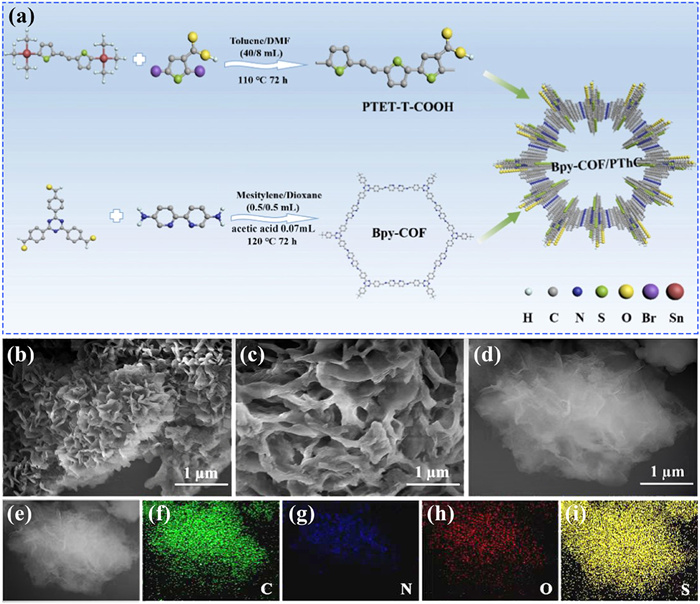
(a) Synthesis process of Bpy-COF/PThC heterojunction. Scanning electron microscopy (SEM) images of (b) Bpy-COF, (c) PThC and (d) 30% Bpy-COF/PThC. (e-i) Mapping images of 30% Bpy-COF/PThC.
Environmentally friendly Bpy-COF/PThC all-organic heterojunction for efficient removing antibiotic-resistant bacteria and organic pollutants
Feng Liu , Liaofang Shang , Yao Liu , Xinyue Zhang , Chunbo Liu , Guangbo Che , Haiyong Guo , Yaqian Lan

Antibiotic-resistant bacteria (ARB) and organic pollutants in the aquatic environment pose a significant threat to environmental safety and human health [1-4]. Represented by methicillin-resistant Staphylococcus aureus (MRSA), MRSA is one of the primary pathogens responsible for hospital infections. It exhibits multidrug resistance and strong pathogenicity, capable of causing skin and soft tissue infections, bloodstream infections, and infections of various organs throughout the body. Infections caused by this bacterium are difficult to treat and have a high mortality rate [5-8]. Therefore, eliminating antibiotic-resistant bacteria and other organic pollutants is of great significance for sustainable human development.
Due to the disadvantages of traditional chemical and physical sterilization methods, such as high cost, cumbersome operation process, incomplete sterilization, and high biological toxicity of by-products, their industrial application has been hindered [9-11]. Therefore, it is urgent to develop new, efficient, and green technologies for removing pathogenic microorganisms from water bodies. Photocatalytic sterilization technology has been widely studied in recent years due to its advantages of strong oxidation capacity, low energy consumption, and mild reaction conditions. It has broad application prospects and great development potential in removing organic pollutants and ARBs [12-15]. Designing and developing efficient, safe, and bacteria-resistant novel antimicrobial materials is the key to photocatalytic sterilization technology.
Currently, inorganic semiconductor photocatalytic antibacterial materials, such as ZnO, TiO2, and Ag3PO4, are widely studied [16-18]. However, most inorganic semiconductor photocatalysts suffer from high photogenerated carrier recombination rates, low quantum efficiency, and wide band gaps, which hinder their effective utilization of visible light [19-23]. Additionally, the potential biological toxicity of the metal elements they contain greatly limits their widespread use [24-27]. Compared to inorganic materials, organic semiconductor materials possess numerous unparalleled advantages such as abundant resources, precise design of molecular structure, tunable electronic structure and light absorption, as well as diverse self-assembly morphologies and functions [28-31].
Therefore, there is an urgent need to develop efficient, environmentally friendly, and biocompatible organic antibacterial materials.
Polythiophene is a class of conjugated polymers characterized by excellent photophysical properties, low toxicity, high stability, and ease of modification. It is widely used in fields such as biological imaging, bacterial inactivation, and sensing [32-36]. In previous work, our research group copolymerized 2,5-dibromothiophene-3-carboxylic acid monomer with the planar T-E-T-Tin monomer through palladium-catalyzed Stille coupling reaction, obtaining a thiophene-based polymer PThC with a regular chain structure. This polymer can kill approximately 99.9% of MRSA after being irradiated with visible light for about 2 h [37]. However, polythiophene has a high recombination rate of photogenerated carriers, resulting in low photocatalytic performance and limiting its practical applications [34-39]. Constructing heterojunction composite materials with tightly contacted interfaces is one of the most effective strategies to enhance carrier transport efficiency [40-44].
The novel porous crystalline covalent-organic frameworks (COFs) are considered as ideal platforms for achieving this goal, owing to their advantages such as abundant catalytic sites, large specific surface area and structural diversity [45-48]. COF-based antimicrobial agents possess numerous advantages over other porous materials. Their robust covalent bonds confer high stability, making them suitable for various antimicrobial conditions. Furthermore, their regular, long-range open nanopores provide a stable microenvironment and rapid diffusion channels for reactive oxygen species (ROS). Their conjugated π system and open planar structure can effectively promote light absorption and carrier transport. More importantly, COFs do not contain unstable and harmful metals or metal oxides, making them highly safe and practical for biomedical applications. Therefore, the value of COFs in antimicrobial applications has been continuously explored [49-52]. For instance, Liu et al. [51] synthesized five COFs with different nitrogen atom positions using p-phenylenediamine with varying numbers and positions of heterocyclic nitrogen atoms as precursors, and applied them to the inactivation of E. coli. Their study revealed that by embedding heterocyclic N atoms in the precursor, the local electronic structure of the COF can be optimized, enhancing charge interaction and quantum efficiency, thereby improving the photocatalytic sterilization performance of the COF. This provides a new approach for developing novel multifunctional water disinfection photocatalysts based on COF materials. Additionally, constructing COF heterojunction composites and using them for photocatalytic antibacterial activity has also become a hot research area. For example, Lv et al. [52] synthesized a MIL-88B@COF-200@10% PANI composite using a stepwise self-assembly method. The results showed that the type Ⅱ heterojunction constructed from bimetallic Fe.Co-MIL-88B and spherical COF-TPA/TPB can effectively promote the separation and transfer of photoinduced carriers. Compared to the monomers, the Fe.Co-MIL-88B@COF-200@10% PANI composite exhibited superior killing effects on E. coli and Staphylococcus aureus.
However, research on photocatalytic antibacterial materials based on PThC and COF is relatively scarce and urgently needs to be explored. Based on this, we prepared a high-performance conductive polymer PThC through the Stille coupling reaction and a bipyridine covalent organic framework Bpy-COF through acid-catalyzed imine condensation. Leveraging the π-π stacking and hydrogen bonding interactions between Bpy-COF and PThC, we successfully fabricated a novel Bpy-COF/PThC all-organic heterojunction. We systematically investigated the chemical structure, photoelectrochemical properties, photocatalytic degradation of organic pollutants, and sterilization performance and mechanism of the photocatalyst. Additionally, the safety of the photocatalyst was evaluated through cytotoxicity experiments. The research results provide new design ideas for constructing efficient and safe organic photocatalysts, and offer a theoretical basis for water pollution control and treatment.
Preparation of PTET-T-COOH: Under nitrogen protection, T-E-T-Tin (200 mg, 0.386 mmol) and 2,5-dibromo-3-thiophene carboxylic acid (110.42 mg, 0.386 mmol) dissolved in anhydrous toluene (40 mL) were added to the reaction flask. Then, anhydrous DMF (8 mL) and Pd (PPh3) 4 (70 mg, 0.038 mmol) were added. The mixture was stirred at 110 ℃ for 72 h under conditions of anhydrous and anaerobic conditions. Then, the solvent was removed by rotary evaporation, washed with anhydrous ethanol, and dried overnight in a vacuum oven at 80 ℃. After soxhlet extraction with anhydrous ethanol, acetone and n-hexane for 24 h each, they were dried to obtain a reddish-brown solid (180 mg, 89%). After 24 h of Soxhlet extraction with anhydrous ethanol, acetone, and n-hexane, a reddish brown solid (180 mg, 89%) was obtained by drying.
Preparation of Bpy-COF: 2,4,6-Tris(4-aldehyde phenyl)-1,3,5-triazine (TFPT, 15.73 mg) and 5,5′-diamino-2,2′-bipyridine (Bpy, 11.17 mg) were added to a high-temperature resistant glass tube after grinding, then 1,4-dioxane (0.5 mL), m-trimethylbenzene (0.5 mL), and anhydrous acetic acid (0.07 mL 6 mol/L) were added. The glass tube was frozen and vacuumed with liquid nitrogen, sealed with a flame spray gun, and placed in an oven at 120 ℃ for 3 days to obtain orange solid products. The product was washed three times with acetone and dried.
Preparation of Bpy-COF/PThC heterojunction: 14 mg PTET-T-COOH was dissolved in 20 mL tetrahydrofuran, and after ultrasound for 1 h, it was added drop by drop to the mixed solution composed of 6 mg Bpy-COF and 20 mL anhydrous ethanol. 30% Bpy-COF/PThC was obtained by mechanical stirring for 5 h at room temperature and away from light. By changing the monomer mass, 10%, 20%, 40%, and 50% Bpy-COF/PThC composites were prepared, respectively. The solvent was evaporated by rotation, washed with ethanol, and dried in a vacuum drying oven.
The characterization methods of the materials, as well as the evaluation of their biotoxicity testing and photocatalytic activity, are described in detail in Supporting information.
As shown in Fig. 1a, a high-performance conductive polymer PTET-T-COOH (PThC) was prepared via the Stille coupling reaction, and a bipyridine (Bpy) covalent organic framework Bpy-COF was synthesized through acid-catalyzed imine condensation. By utilizing the π-π stacking and hydrogen bonding interactions between Bpy-COF and PThC, a Bpy-COF/PThC type Ⅱ heterojunction was successfully fabricated.
The morphology and microstructure of the composite were observed using SEM. From Fig. 1b, it can be seen that Bpy-COF is a flower-like cluster composed of stacked nanosheets. Fig. 1c reveals that PThC possesses a distinct porous structure, with interconnected channels that can provide more pathways for charge transfer. As observed in Figs. 1d-i, Bpy-COF and PThC are in close contact, and elements such as C, N, O, and S are uniformly distributed in the material, proving the successful synthesis of the heterojunction. The high-resolution transmission electron microscopy (HR-TEM) images of Bpy-COF (Fig. S1 in Supporting information) and Bpy-COF/PThC (Fig. S2 in Supporting information) both exhibit clear lattice fringes with a spacing of 0.28 nm, similar to other reported COFs [53,54]. As shown in Fig. 2a, the zeta potentials of Bpy-COF and PThC are −15.4 and −11.2 mV, respectively, indicating that they cannot be complexed through electrostatic attraction. Considering the π-electron conjugated system and carboxyl group of PThC, it is speculated that PThC can be tightly bound to Bpy-COF rich in aromatic groups through π-π interactions.
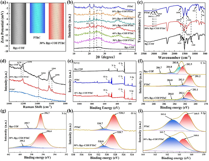
The structural characteristics of the material were analyzed using XRD, FTIR, and Raman spectroscopy. As depicted in Fig. S3, the obvious diffraction peak of Bpy-COF at 2θ = 2.44° corresponds to the (100) lattice plane, indicating the presence of open channels [55-57]. The broad peak of Bpy-COF in the range of 25°−30° is attributed to the (001) crystallographic plane, suggesting the π–π stacking of 2D layers along the c direction [58-60]. PThC has three distinct characteristic peaks at 20.2°, 23.0° and 39.0°. The broad diffraction peak at 23.0° is attributed to the π-π stacking form [61]. With the increase of the mass fraction of Bpy-COF, the characteristic peak of Bpy-COF in Bpy-COF/PThC composites gradually increases, while the diffraction peak intensity of PThC gradually weakens. As displayed in Fig. 2c, the FT-IR peak at 1698 cm-1 is attributed to the C=O stretching mode of the carboxyl group [62]. The peaks at 3063, 3015 and 2919 cm-1 are related to the C—H stretching mode. The peak at 1557 cm-1 is caused by O—H vibration. The peaks at 934 and 791 cm-1 are attributed to the =C−H and C−H deformation vibrations, respectively. As exhibited in Fig. 2d, the peaks at 1170 and 1194 cm-1 are associated with the in-plane ring C—H bending and stretching vibrations. Both Bpy-COF and PThC have obvious peaks at 1416 cm-1, which is consistent with the C=C vibration mode of fat. The peaks at 1566 and 1606 cm-1 in Bpy-COF are generated by the stretching vibration of aromatic C=C bonds in the plane [63]. In addition, the peak position of 30% Bpy-COF/PThC is blue-shifted relative to Bpy-COF, which may also be the result of π-π interactions [63]. The aforementioned observations discovered in Raman spectroscopy are consistent with the results obtained from FTIR spectroscopy, revealing the formation of chemical bonds between Bpy-COF and PThC, rather than simple mixing.
The surface chemical valence states of Bpy-COF, PThC, and 30% Bpy-COF/PThC were studied using XPS. As shown in the total spectrum of Fig. 2e, the presence of C, N, O, and S elements in the heterojunction is demonstrated, with N 1s originating from Bpy-COF, O 1s and S 2p originating from PThC, and C 1s originating from both monomers, confirming the successful preparation of the heterojunction. Fig. 2f is a C 1s spectrum, and all three samples have a peak at 284.8 eV, which corresponds to the graphite C—C bond [64]. The C 1s spectra of Bpy-COF display four distinct peaks at 282.5, 283.0, 284.8 and 286.7 eV, corresponding to C—C, C—N, C=O and π-π excitation, respectively [65,66]. Fig. 2g shows the N 1s spectrum, with 396.7 and 399.7 eV corresponding to the R-CN and pyridine C—N—H bonds, respectively [67-69]. The O 1s spectrum (Fig. 2h) shows two characteristic peaks at 528.3 and 530.7 eV for PThC, corresponding to the O=C bond and adsorbed -OH oxygen, respectively [32-34]. The characteristic peaks of S 2p at 160.5 and 161.5 eV (Fig. 2i) can be attributed to S 2p1/2 and S 2p3/2, respectively [37,38]. Notably, the N peak in the heterojunction shifts towards lower binding energy, while the peak positions of O 1s and S 2p shift towards higher binding energy, indicating that Bpy-COF gains electrons (e-), while PThC loses electrons. In the heterojunction, electrons move from PThC to Bpy-COF, leading to an increase in electron density on the surface of Bpy-COF, further confirming the strong interfacial interaction between Bpy-COF and PThC.
Targeting MRSA as the drug-resistant bacteria, the photocatalytic antibacterial activities of the materials were investigated. As shown in Fig. 3a, PThC and Bpy COF can only kill approximately 1.00 log and 0.48 log of MRSA, respectively, within 60 min. The Bpy-COF/PThC heterojunction exhibits superior antibacterial efficacy compared to Bpy-COF and PThC alone. When the loading ratio of Bpy-COF increases from 10% to 30%, the photocatalytic antibacterial efficiency of the heterojunction gradually improves. This can be explained by the fact that the loaded Bpy-COF improves the separation efficiency of photogenerated carriers in the heterojunction, facilitating the generation of more active species. However, as the loading amount of Bpy-COF continues to increase, the photocatalytic antibacterial efficiency of the heterojunction gradually decreases. This is mainly because excessive Bpy-COF reduces the exposed active sites of the composite, thereby decreasing the production of active species. From Fig. 3b, it can be seen that 30% Bpy COF/PThC exhibits the best antibacterial effect, killing 99.96% of bacteria after 60 min of irradiation and demonstrating better bactericidal performance than other reported organic photocatalysts (Table S1 in Supporting information). Moreover, the reaction rate constant of 30% Bpy-COF/PThC is the highest (1.48 min-1), which is 21.14 times and 9.80 times higher than that of Bpy-COF (0.07 min-1) and PThC (0.151 min-1), respectively (Fig. S4 in Supporting information). The above results demonstrate that the enhanced antibacterial capability of the composite is attributed to the formation of a heterojunction.
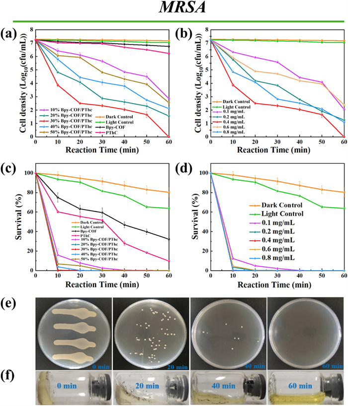
By changing the amount of catalyst added, the inactivation ability of 30% Bpy-COF/PThC with different concentrations (0.1, 0.2, 0.4 and 0.6 mg/mL) against MRSA was investigated. As shown in Figs. 3c and d, when the catalyst concentration increases from 0.1 mg/mL to 0.4 mg/mL, the antibacterial performance of the photocatalyst is enhanced. However, when the concentration increases to 0.6 mg/mL, the antibacterial performance decreases. This is because high doses of photocatalysts can lead to increased light scattering and decreased light transmittance, ultimately resulting in a decrease in the number of active species. After 60 min of photocatalytic reaction between 0.4 mg/mL 30% Bpy-COF/PThC and bacteria, there are almost no bacterial colonies on the agar plate (Fig. 3e), and the rabbit plasma is in a completely flowing state (Fig. 3f), indicating that the bacteria has been completely inactivated at this time.
The potential for practical application of the material was further investigated through photocatalytic antibacterial experiments under natural light exposure. As shown in Figs. 4a and b, it can be observed that the bacterial density in the control group and the Bpy-COF treatment group remain almost unchanged. The bactericidal rate of PThC reaches 60% after 1 h of natural light exposure. However, the bactericidal rate of the 30% Bpy-COF/PThC composite significantly increases to 96% after 1 h of natural light exposure, and it can completely kill 7.43 log of MRSA after 3 h (Fig. 4c), indicating that the Bpy-COF/PThC heterojunction still exhibits excellent antibacterial performance under natural light exposure.
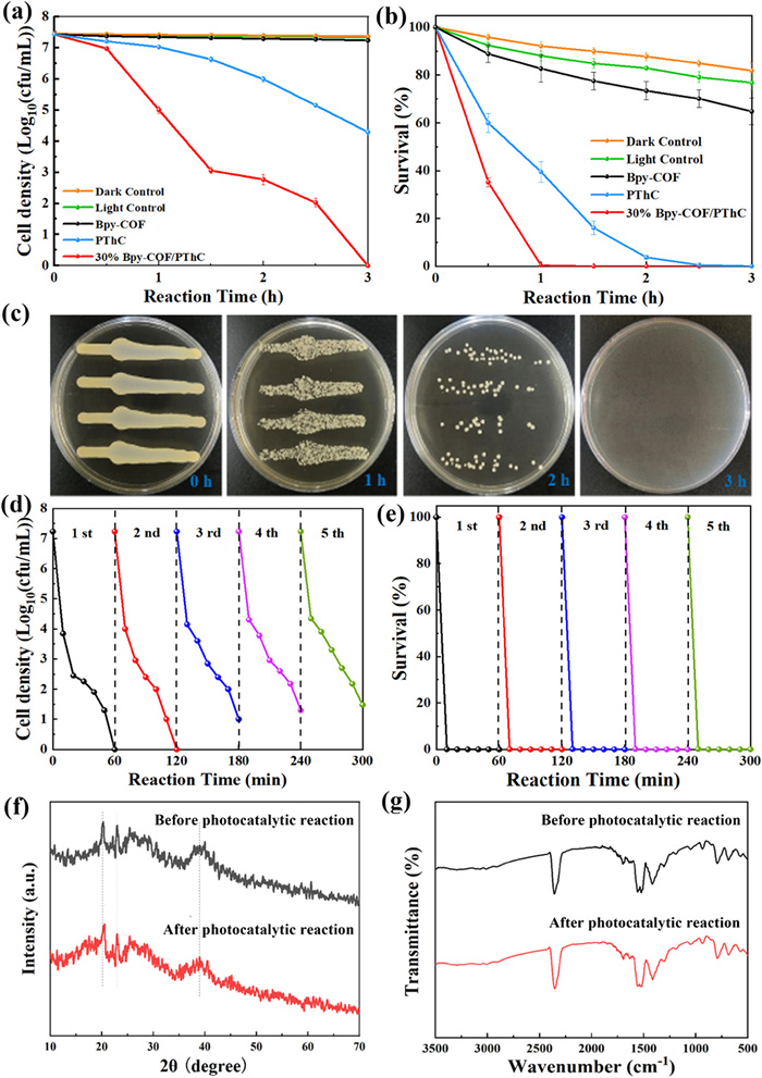
To investigate the recyclability and stability of the 30% Bpy-COF/PThC heterojunction, five cycles of photocatalytic sterilization experiments were conducted. Experimental data indicate that after five cycles of repeated use, the composite still exhibits high antibacterial activity, maintaining an inactivation rate of over 95% against MRSA bacteria (Figs. 4d and e). A possible reason for the slight decrease in photocatalytic antibacterial efficiency is the loss of a small amount of photocatalyst during the recycling and collection process. Another possible cause is slight light corrosion caused by prolonged simulation of sunlight exposure [42]. The XRD (Fig. 4f) and FT-IR (Fig. 4g) spectral images of the composite before and after the photocatalytic reaction are almost identical, indicating that the chemical structure of the composite is relatively stable and can be recycled for reuse.
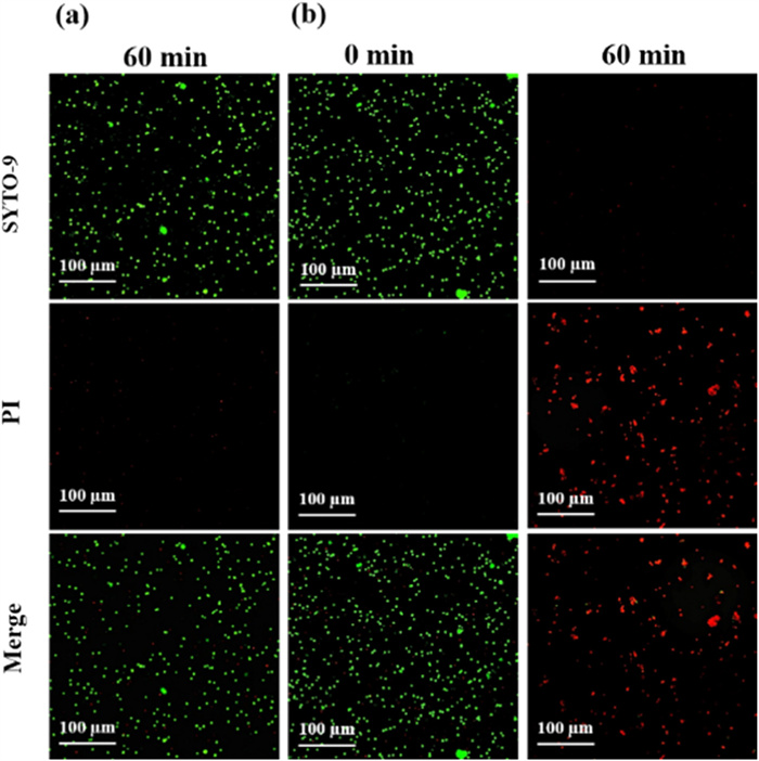
The live/dead bacterial staining experiment can visually demonstrate the bactericidal effect of photocatalytic materials. As shown in Fig. 5, after 60 min of visible light irradiation, the MRSA cells in the control group (without photocatalyst) exhibit green fluorescence, indicating that the cells are still alive. However, all MRSA cells treated with the 30% Bpy-COF/PThC heterojunction exhibit obvious red fluorescence, indicating that the bacteria have been inactivated.
The morphological changes of MRSA cells before and after the reaction were observed by SEM and TEM, further investigating the mechanism of bacterial inactivation. From Fig. 6a, it can be seen that before the photocatalytic reaction, most MRSA cells were encapsulated by the material, and the bacteria on the material surface present as round, grape-like shapes with intact cell walls. After the reaction, wrinkles and depressions appear on the cell surface (Fig. 6b). From the TEM images of MRSA cells before and after the reaction (Figs. 6c-f), it can be observed that after the photocatalytic reaction, the bacterial cell walls are damaged.
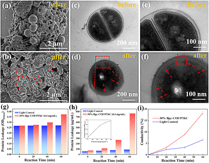
When bacterial cells are damaged, their permeability increases, leading to the leakage of inorganic salts and proteins from the body. By testing the protein content and conductivity of bacterial suspensions at different reaction times, we can further investigate the inactivation mechanism of bacteria. As the photocatalytic reaction time increases, there is no significant change in the protein leakage amount of MRSA cells in the control group, while the protein leakage amount in the experimental group gradually increases (Figs. 6g and h). Fig. 6i shows that the conductivity of the bacterial suspension in the experimental group increases with the extension of reaction time. The conductivity value at 60 min is approximately 17.5 times that at 0 min and 3.5 times that at 60 min in the control group. The above experimental results indicate that the Bpy-COF/PThC heterojunction under illumination can rupture the cell membrane of MRSA cells, leading to the leakage of contents such as inorganic salts and proteins, thereby inactivating the bacteria.
The broad-spectrum bactericidal potential of the material was further investigated through photocatalytic inactivation experiments of E. coli under visible and natural light irradiation. Experimental data indicates the antibacterial performance of 30% Bpy-COF/PThC against E. coli under visible or natural light is significantly better than that of Bpy-COF and PThC. After 2 h of visible light irradiation, 2.75 log of bacteria can be killed, with a bactericidal rate of 99.83% (Fig. S5 in Supporting information). The antibacterial activity of 30% Bpy-COF/PThC against E. coli is slightly lower than its antibacterial activity against MRSA. This may be due to the protective effect of the outer membrane of E. coli, which makes it difficult for free radicals to penetrate the cell wall [70]. Under natural light irradiation for 2 h, the composite material can kill 98.22% of E. coli (Fig. S6 in Supporting information), indicating that the Bpy-COF/PThC heterojunction has excellent broad-spectrum bactericidal capability.
The photocatalytic degradation capability of the composite towards environmental pollutants was evaluated through degradation experiments of RhB (Fig. 7a), MB (Fig. 7b), and TC (Fig. 7c) under simulated sunlight. The experimental results indicate that after 180 min of exposure to light, the degradation rate of RhB by 30% Bpy-COF/PThC is 94.8%, whereas the degradation rates of RhB by Bpy-COF and PThC are only 30.47% and 13.13%, respectively. The reaction rate constant (3.09 min-1) of the composite is 8.58 times and 23.76 times higher than that of Bpy-COF (0.36 min-1) and PThC (0.13 min-1), respectively (Fig. 7d). Moreover, the degradation rate constants (1.03 and 0.51 min-1) of MB (Fig. 7e) and TC (Fig. 7f) by the 30% Bpy-COF/PThC heterojunction are also significantly higher than those by Bpy-COF (0.21 and 0.14 min-1) and PThC (0.34 and 0.14 min-1). The experimental data demonstrate that the degradation performance of the composite for the three pollutants is significantly superior to that of Bpy-COF and PThC. To further evaluate the removal capability of the photocatalyst towards pollutants, the removal rate of total organic carbon (TOC) by the composite was tested. As shown in Fig. S7 (Supporting information), the TOC mineralization rates reach 56.86% for RhB, 46.02% for MB, and 14.63% for TC, respectively. These results demonstrate that the composite exhibits excellent degradation activity towards various environmental pollutants.
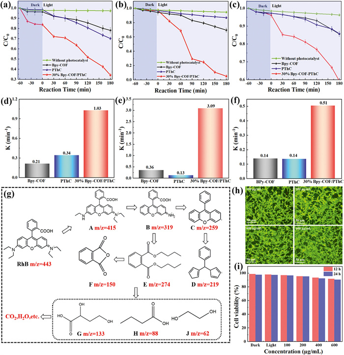
The degradation pathway and intermediates of RhB in the photocatalytic process were further studied using high-performance liquid chromatography-mass spectrometry (HPLC-MS) technology. As exhibited in Fig. S8 (Supporting information) and Fig. 7g, RhB (m/z = 443) undergoes N-demethylation to produce substance A (m/z = 415), which decomposes to generate product B (m/z = 319), and B undergoes decarboxylation to produce product C (m/z = 259). Meanwhile •O2- and •OH radicals are cleaved to produce product E (m/z = 274), which is then converted to product F (m/z = 150) [71,72]. Intermediate product D (m/z = 219) can undergo cleavage as a chromophore [73,74]. Under the action of active species, the macromolecular intermediate undergoes oxidation, ring-opening reactions, and removal of functional groups, gradually decomposing into several small molecular intermediates, such as products G (m/z = 133), H (m/z = 88), and J (m/z = 62), and ultimately decomposing into H2O and CO2.
To evaluate the biotoxicity of the 30% Bpy-COF/PThC heterojunction, the composite with different concentrations were co-cultured with NIH3T3 cells. As displayed in Fig. 7h, with the increase in the concentration of the composite (100, 200, 400, 600 µg/mL), there is no significant change in the morphology of the cells, and most of the cells survive (green fluorescence). In Fig. 7i, after co-culturing the composite with NIH3T3 cells for 12 and 24 h, the decrease in cell viability is relatively small, indicating that the 30% Bpy-COF/PThC heterojunction has low biotoxicity and good biocompatibility towards NIH3T3 cells.
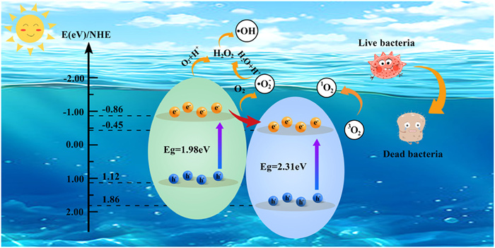
The optical properties of the composites were evaluated by UV–vis diffuse reflectance spectroscopy (Fig. 8a). Based on the Tauc plot method, the band gap energies (Eg) of Bpy-COF, PThC, and 30% Bpy-COF/PThC were calculated to be approximately 2.31, 1.98, and 1.93 eV, respectively (Fig. 8b). The ordered π-induced stacking structure of Bpy-COF/PThC enhances its light absorption capability and optimizes its bandgap, rendering it an efficient generator of ROS [75-77].
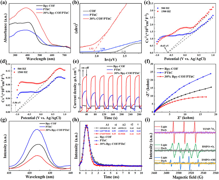
By measuring the Mott-Schottky curves at different frequencies, the flatband potentials of Bpy-COF (Fig. 8c) and PThC (Fig. 8d) are determined to be −0.65 V vs. Ag/AgCl (−0.45 V vs. normal hydrogen electrode [NHE]) and −1.06 V vs. Ag/AgCl (−0.86 V vs. NHE), respectively. Additionally, both Bpy-COF and PThC exhibit positive slopes, indicating that they are n-type semiconductors. For n-type semiconductors, the flatband potential is approximately equal to conduction band (CB) potential [40-42]. Therefore, it can be inferred that the conduction band (CB) positions of Bpy-COF and PThC are −0.45 and −0.86 eV, respectively, while the valence band (VB) positions are 1.86 and 1.12 eV, respectively. Therefore, the energy band structures of Bpy-COF and PThC are intertwined, which is conducive to the formation of stable and efficient heterojunctions, thereby facilitating the separation and transport of photogenerated carriers.
The photogenerated carrier transfer efficiency of the heterojunction was investigated through EIS, PL, TRPL and photocurrent response spectra (Fig. 8e). Experimental data reveal that 30% Bpy-COF/PThC exhibits the lowest charge transfer resistance (Fig. 8f) and PL fluorescence intensity (Fig. 8g), along with the highest photocurrent response intensity, indicating its superior charge separation efficiency. As evident from Fig. 8h, the fluorescence lifetime of the composite (0.35 ns) is shorter than that of Bpy-COF (0.63 ns) and IDT-COOH (0.60 ns), suggesting that short-lived carriers can enhance the photocatalytic activity by rapidly generating highly reactive species. Through π-π interactions, the heterojunction forms a tight contact interface, effectively reducing the interface resistance and greatly facilitating the efficient separation of space charges, which is conducive to the generation and transport of active radicals [78-80].
The types and contributions of active species in the photocatalytic antibacterial process were investigated through radical trapping experiments and ESR tests. Under visible light, NaN3, EDTA-2Na, K2Cr2O7, l-ascorbic acid, and isopropanol were used as trapping agents for 1O2, h+, e-, •O2-, and •OH, respectively. Fig. S9a (Supporting information) shows the toxicity test results of various capture agents, and the experimental data indicate that the various capture agents themselves do not have a significant inactivation effect on bacteria. From Fig. S9b (Supporting information), it can be seen that the photocatalytic antibacterial activities of Bpy-COF/PThC heterojunction are inhibited to varying degrees after adding various capture agents, and the contribution rates of each active species are in the order of e- > 1O2 > •O2- > •OH > h+. The content of active species was further determined using ESR testing. As shown in Fig. 8i, there is no obvious signal peak under dark conditions, while under visible light irradiation, the Bpy-COF/PThC heterojunction can generate 1O2, •OH and •O2-.
Based on the aforementioned research results, the photogenerated charge separation pathway and photocatalytic reaction mechanism of the Bpy-COF/PThC heterojunction are proposed. As illustrated in Fig. 9, the conduction band of PThC is −0.86 eV vs. NHE, while that of Bpy-COF is −0.45 eV vs. NHE. The conduction band position of PThC is higher than that of Bpy-COF. Under visible light irradiation, e- on the CB of PThC can transfer to the CB of Bpy-COF, while h+ on the VB of Bpy-COF simultaneously migrate to the VB of PThC. The formation of the Bpy-COF/PThC heterojunction facilitates the separation of photogenerated carriers. Electrons can be captured by O2 to generate •O2- (O2/•O2- = −0.33 eV vs. NHE), and 3O2 is converted to 1O2 through an energy transfer process [34]. Since the VB position of PThC (1.12 eV vs. NHE) and the VB potential of Bpy-COF (1.86 eV vs. NHE) are more negative than the potential of OH-/•OH (1.99 eV vs. NHE) and H2O/•OH (2.27 eV vs. NHE), it is difficult to oxidize H2O/OH- to •OH under visible light irradiation. However, more H2O2 can be generated through the two-electron reduction reaction of O2 and H+, which can then be converted to •OH, further enhancing the oxidation capability of the composite system. Under the combined action of •O2-, h+, •OH, and 1O2, the Bpy-COF/PThC heterojunction can degrade and mineralize organic matter into small molecular products such as CO2 and H2O. Meanwhile, these ROS possess highly unstable redox potentials, capable of killing a wide range of bacteria within a short period of time. Its specific bactericidal mechanism encompasses the following aspects. The generated ROS can damage the cellular components of bacteria, attack the cell wall, and tear apart the cell membrane. Subsequently, ROS react with cellular proteins, typically targeting the amino/carboxyl functional groups in amino acids, disrupting the peptide bonds within amino acids, leading to leakage of intracellular contents and protein denaturation. Additionally, ROS can oxidize enzymes required for glucose decomposition in bacteria, causing metabolic disorders and thus inhibiting bacterial growth. ROS molecules can also directly react with bacterial DNA and RNA, damaging their genetic material and preventing normal replication and reproduction of bacteria. Ultimately, this leads to the death of E. coil and MRSA cells [81-84].
In summary, the Bpy-COF/PThC heterojunction exhibits higher light absorption performance, faster separation and migration efficiency of photogenerated carriers, and stronger oxidation capability, thus significantly improving its photocatalytic performance in removing organic pollutants and drug-resistant bacteria.
In conclusion, a Stille coupling reaction was employed to prepare a thiophene-based conjugated polymer, which was then compounded with a bipyridine covalent organic framework to successfully fabricate a novel Bpy-COF/PThC all-organic heterojunction. Characterization results such as XRD, FT-IR, Raman, XPS, and SEM demonstrate the successful preparation of the Bpy-COF/PThC heterojunctions. The π-π stacking interaction between Bpy-COF and PThC aids in charge separation. Antibacterial experiments indicate good photocatalytic performance against both MRSA and E. coli under both LED light and natural light. Under LED light, 7.23 log of MRSA can be completely killed within 60 min, and the sterilization rate for E. coli reaches 99.83% after 2 h. Protein leakage, conductivity, live/dead bacterial fluorescence experiments, as well as SEM and TEM images after bacterial reaction, reveal that the cell wall is destroyed, leading to bacterial death. When irradiated with LED light for 180 min, degradation rates of 94.80%, 65.81%, and 40.67% are achieved for RhB, MB, and TC, respectively, demonstrating the universality of 30% Bpy-COF/PThC for pollutant degradation. Mechanism analysis shows that this type Ⅱ heterojunction can achieve efficient electron-hole pair separation and carrier transport. Cytotoxicity testing results indicate that the material has good biocompatibility and potential for practical applications. The research findings provide new design ideas for constructing efficient and safe organic photocatalysts.
The authors declare that they have no known competing financial interests or personal relationships that could have appeared to influence the work reported in this paper.
Feng Liu: Writing – original draft. Liaofang Shang: Data curation. Yao Liu: Formal analysis. Xinyue Zhang: Funding acquisition. Chunbo Liu: Data curation. Guangbo Che: Writing – review & editing. Haiyong Guo: Investigation. Yaqian Lan: Conceptualization.
This work is supported by the Science and Technology Research Project of the Education Department of Jilin Province (No. JJKH20240576KJ), the Natural Science Foundation Project of Jilin Province (Nos. YDZJ202402054CXJD, YDZJ202401468ZYTS), the National Natural Science Foundation (No. 22478150), the Science and Technology Development Plan Project of Siping City (No. 2023080) and Undergraduate Innovation and Entrepreneurship Training Program Project of Jilin Normal University (No. 202410203072).
Supplementary material associated with this article can be found, in the online version, at doi:
S. Wang, C. Li, H. Yin, et al., Environ. Res. 264 (2025) 120313. doi: 10.1016/j.envres.2024.120313
F. Ishaque, R.K. Manoharan, Y.H. Ahn, Chem. Eng. J. 489 (2024) 151240. doi: 10.1016/j.cej.2024.151240
F.P. Yang, J. Shi, Y.S. Wei, et al., Chin. Chem. Lett. 36 (2025) 109746. doi: 10.1016/j.cclet.2024.109746
T. Li, C.Y. Li, Y.F. Wang, et al., J. Hazard. Mater. 477 (2024) 135357. doi: 10.1016/j.jhazmat.2024.135357
Q. Fang, N. Liu, Y. Gu, et al., Sep. Purif. Technol. 335 (2024) 126122. doi: 10.1016/j.seppur.2023.126122
Z. Lin, S. Ye, Y. Xu, et al., Chem. Eng. J. 453 (2023) 139747. doi: 10.1016/j.cej.2022.139747
Z. Yu, Y. Zhou, H. Zhang, et al., Environ. Pollut. 358 (2024) 124500. doi: 10.1016/j.envpol.2024.124500
F. Zhang, S. Cheng, J. Zhao, et al., J. Environ. Manage. 348 (2023) 119194. doi: 10.1016/j.jenvman.2023.119194
J. Xu, P. Liang, X. Shen, et al., Sep. Purif. Technol. 339 (2024) 126734. doi: 10.1016/j.seppur.2024.126734
X. Yu, Z. Wang, Y. Lou, et al., Chem. Eng. J. 484 (2024) 149552. doi: 10.1016/j.cej.2024.149552
X. Lin, C. Zhang, R. Han, et al., ISME J. 17 (2023) 2003–2013. doi: 10.1038/s41396-023-01514-w
Y. Liu, W. Dong, X. Jiang, et al., Environ. Sci. Technol. 57 (2023) 12105–12116. doi: 10.1021/acs.est.3c03103
Y. Liu, Y. Cai, G. Li, et al., Water Res. 218 (2022) 118407. doi: 10.1016/j.watres.2022.118407
X.D. Yang, J. Duan, X. Zhang, et al., Chin. Chem. Lett. 33 (2022) 3792–3796. doi: 10.1016/j.cclet.2021.11.031
M. Yu, D.W. Liu, L.C. Wang, et al., Appl. Catal. B: Environ. 350 (2024) 123922. doi: 10.1016/j.apcatb.2024.123922
N. Thakur, N. Thakur, A. Kumar, et al., Sci. Total Environ. 914 (2024) 169815. doi: 10.1016/j.scitotenv.2023.169815
Z.Q. Wang, Y.J. Gao, T.J. Wang, et al., Chin. Chem. Lett. 36 (2025) 110602. doi: 10.1016/j.cclet.2024.110602
R. Wang, M. Shi, F. Xu, et al., Nat. Commun. 11 (2020) 4465. doi: 10.1038/s41467-020-18267-1
R. Yang, B. Liang, D. Han, et al., J. Alloys Compd. 973 (2024) 172849. doi: 10.1016/j.jallcom.2023.172849
J. Jia, S. Giannakis, D. Li, et al., Sci. Total Environ. 901 (2023) 166376. doi: 10.1016/j.scitotenv.2023.166376
B. Ran, L. Ran, Z. Wang, et al., Chem. Rev. 123 (2023) 12371–12430. doi: 10.1021/acs.chemrev.3c00326
T. Zhou, R. Hu, L. Wang, et al., Angew. Chem. Int. Ed. 132 (2020) 10038–10042. doi: 10.1002/ange.201916704
J. Gao, S. Rao, X. Yu, et al., J. Colloid Interface Sci. 628 (2022) 166–178. doi: 10.1016/j.jcis.2022.07.112
W. Wang, S. Mei, H. Jiang, et al., Chin. J. Catal. 55 (2023) 137–158. doi: 10.1016/S1872-2067(23)64551-6
M.Y. Sun, L. Zhang, Y. Li, et al., Chin. Chem. Lett. 36 (2025) 110035. doi: 10.1016/j.cclet.2024.110035
Q. Zheng, Y. Zhang, Q. Zhang, et al., Chemosphere 319 (2023) 138039. doi: 10.1016/j.chemosphere.2023.138039
M. Herraiz-Carbona, S. Cotillas, E. Lacasa, et al., J. Water Process Eng. 49 (2022) 103035. doi: 10.1016/j.jwpe.2022.103035
X.B. Li, J.Y. Liu, J.T. Huang, et al., Acta Phys. Chim. Sin. 37 (2021) 2010030.
S.Y. Hu, Y.N. Sun, Z.W. Feng, et al., Chemosphere 286 (2022) 131646–131662. doi: 10.1016/j.chemosphere.2021.131646
J.H. You, Y. Zhao, L. Wang, et al., J. Clean. Prod. 291 (2021) 125822–125845. doi: 10.1016/j.jclepro.2021.125822
X.R. Chen, W.R. Cui, R.P. Liang, et al., ACS Appl. Bio Mater. 4 (2021) 6502–6511. doi: 10.1021/acsabm.1c00621
Y.L. Bi, D.Y. Shan, B. Feng, et al., Mater. Today Commun. 34 (2023) 105148. doi: 10.1016/j.mtcomm.2022.105148
J. Du, X.Y. Bai, S.M. Wang, et al., Catal. Lett. 154 (2024) 1865–1883. doi: 10.1007/s10562-023-04409-9
X. Wang, X.H. Li, G.B. Che, et al., ACS Appl. Mater. Interfaces 16 (2024) 6367–6381. doi: 10.1021/acsami.3c16123
C.B. Liu, X.H. Li, P.A. Charpentier, et al., Colloid. Polym. Sci. 302 (2024) 1513–1522. doi: 10.1007/s00396-024-05280-9
X.H. Li, X. Wang, H.Y. Guo, et al., Polym. Chem. 15 (2024) 3617. doi: 10.1039/D4PY00462K
J. Du, S.M. Wang, P.Y. Luo, et al., J. Photoch. Photobio. A 444 (2023) 114973. doi: 10.1016/j.jphotochem.2023.114973
X. Zhao, S.M. Wang, D.Y. Shan, et al., Chem. Eng. J. 495 (2024) 153675. doi: 10.1016/j.cej.2024.153675
X. Zhao, S.M. Wang, J.Y. Wang, et al., J. Hazard. Mater. 488 (2025) 137429. doi: 10.1016/j.jhazmat.2025.137429
X.B. Li, T. Han, Y.T. Zhou, et al., Appl. Catal. B: Environ. 350 (2024) 123913. doi: 10.1016/j.apcatb.2024.123913
S.S. Shen, X.B. Li, Y.T. Zhou, et al., J. Mater. Sci. Technol. 155 (2023) 148–159. doi: 10.1016/j.jmst.2023.03.006
Z.Q. Zan, X.B. Li, X.M. Gao, et al., Acta Phys. Chim. Sin. 39 (2023) 2209016.
S. Zhao, S.S. Shen, L. Han, et al., Rare Met. 43 (2024) 4038–4055. doi: 10.1007/s12598-024-02847-x
X.B. Li, T. Han, Y.T. Zhou, et al., Sci. China Tech. Sci. 67 (2024) 1238–1252. doi: 10.1007/s11431-023-2604-x
M. Lu, S.B. Zhang, M.Y. Yang, et al., Angew. Chem. Int. Ed. 62 (2023) 202307632. doi: 10.1002/anie.202307632
J.N. Chang, J.W. Shi, Q. Li, et al., Angew. Chem. Int. Ed. 62 (2023) 202303606. doi: 10.1002/anie.202303606
J.N. Chang, Q. Li, J.W. Shi, et al., Angew. Chem. Int. Ed. 62 (2023) 202218868. doi: 10.1002/anie.202218868
J.N. Chang, Q. Li, Y. Yan, et al., Angew. Chem. Int. Ed. 61 (2022) 202209289. doi: 10.1002/anie.202209289
J.M. Liu, C.P. Guo, Z.Z. Liu, et al., Chem. Eng. J. 494 (2024) 153139. doi: 10.1016/j.cej.2024.153139
Y.Y. Zhang, X.Q. Xu, Q.B. Liao, et al., J. Mater. Chem. B 10 (2022) 3285. doi: 10.1039/d1tb02808a
F.Y. Liu, Z.Y. Ma, Y.C. Deng, et al., Environ. Sci. Technol. 55 (2021) 5371–5381. doi: 10.1021/acs.est.0c07857
S.W. Lv, J.M. Liu, F.E. Yang, et al., Chem. Eng. J. 409 (2021) 128269–128278. doi: 10.1016/j.cej.2020.128269
F. Xue, J. Zhang, Z.C. Ma, et al., Small 20 (2024) 2307796. doi: 10.1002/smll.202307796
S.L. Zuo, R.M. Zhang, J.H. Huang, et al., Appl. Catal. B: Environ. 371 (2025) 125246. doi: 10.1016/j.apcatb.2025.125246
Y.Z. Kang, B.Y. Zhang, Y. Zhao, et al., Appl. Catal. B: Environ. 355 (2024) 123863. doi: 10.1016/j.apcatb.2024.123863
B.B. Luan, X.Y. Chu, Y. Wang, et al., Adv. Mater. 36 (2024) 2412653. doi: 10.1002/adma.202412653
C.C. Gu, C.Q. Ni, R.J. Wu, et al., J. Colloid Interf. Sci. 658 (2024) 450–458. doi: 10.1016/j.jcis.2023.12.109
J.M. Liu, C.P. Guo, Z.Z. Liu, et al., Chem. Eng. J. 494 (2024) 153139. doi: 10.1016/j.cej.2024.153139
J.F. Kou, G.P. Wang, Z.P. Dong, et al., Appl. Catal. B: Environ. 352 (2024) 124020. doi: 10.1016/j.apcatb.2024.124020
J.Y. Yu, Y. Zheng, B.X. Lv, et al., Appl. Catal. B: Environ. 368 (2025) 125131. doi: 10.1016/j.apcatb.2025.125131
C.B. Liu, W.Z. Xu, P.A. Charpentier, ACS Appl, Polym. Mater. 2 (2020) 1886–1896. doi: 10.1021/acsapm.0c00109
J. Du, Z.Y. Li, H.Y. Guo, et al., Prog. Org. Coat. 165 (2022) 106755. doi: 10.1016/j.porgcoat.2022.106755
L.F. Ning, X. Chen, Z.P. Wang, et al., Appl. Catal. B: Environ. 324 (2023) 122282. doi: 10.1016/j.apcatb.2022.122282
J.D. Yu, Y.Q. He, L.L. Qu, et al., J. Clean. Prod. 274 (2020) 123066. doi: 10.1016/j.jclepro.2020.123066
Z.Y. Xiao, A. Yusuf, Y. Ren, et al., Chem. Eng. J. 497 (2024) 154487. doi: 10.1016/j.cej.2024.154487
T.F. Huang, H. Fan, W. Xiong, et al., Anal. Methods 17 (2025) 1362–1370. doi: 10.1039/d4ay01738b
Q.Z. Gao, J. Xu, Z.P. Wang, et al., Appl. Catal. B: Environ. 271 (2020) 118933. doi: 10.1016/j.apcatb.2020.118933
S. Qi, R. Guo, Z. Bi, et al., Small 19 (2023) 2303632. doi: 10.1002/smll.202303632
Y.S. Xu, E.Z. Hu, D.Y. Xu, et al., Sep. Purif. Technol. 274 (2021) 119081. doi: 10.1016/j.seppur.2021.119081
Q. Yue, J. Yu, Q.P. Zhu, et al., Chem. Eng. J. 486 (2024) 150345. doi: 10.1016/j.cej.2024.150345
L.S. Wang, H.S. Yin, S. Wang, et al., Appl. Catal. B: Environ. 305 (2022) 121039. doi: 10.1016/j.apcatb.2021.121039
S.J. Li, M.J. Cai, Y.P. Liu, et al., Chin. J. Catal. 43 (2022) 2652–2664. doi: 10.1016/S1872-2067(22)64106-8
S.J. Li, C.C. Wang, M.J. Cai, et al., Chem. Eng. J. 428 (2022) 131158. doi: 10.1016/j.cej.2021.131158
K. Saravanakumar, V. Maheskumar, Y. Yea, et al., Compos. Part B: Eng. 234 (2022) 109726. doi: 10.1016/j.compositesb.2022.109726
L.G. Ding, M. Shi, Y.L. Xu, et al., Adv. Funct. Mater. 25 (2025) 2411237.
W.X. Wu, W.Z. Liu, Y.Y. Jing, et al., Nano Res. 18 (2025) 94907161. doi: 10.26599/nr.2025.94907161
B.W. Ma, X.Y. Lin, T.T. Zhu, et al., Surf. Interfaces 62 (2025) 106226. doi: 10.1016/j.surfin.2025.106226
X.J. Lin, M. Zhang, W.X. Lv, et al., Adv. Funct. Mater. 34 (2024) 2310845. doi: 10.1002/adfm.202310845
B.W. Ma, X.Y. Lin, T.T. Zhu, et al., Colloid Surface B 242 (2024) 114101. doi: 10.1016/j.colsurfb.2024.114101
F.Y. Wang, H.X. Zhang, S.H. Ma, et al., J. Colloid Interf. Sci. 693 (2025) 137593. doi: 10.1016/j.jcis.2025.137593
P.X. Li, B. Li, C.F. Wang, et al., Compos. Part B 252 (2023) 110506. doi: 10.1016/j.compositesb.2023.110506
X.Y. Wu, T.T. Feng, X.H. Zhu, et al., Chem. Eng. J. 496 (2024) 154179. doi: 10.1016/j.cej.2024.154179
Y. Li, L.Q. Liu, T. Meng, et al., ACS Nano 17 (2023) 2932–2942. doi: 10.1021/acsnano.2c11339
J. Li, M. Zhang, Y.Y. Wang, et al., ACS Nano 18 (2024) 35606–35619. doi: 10.1021/acsnano.4c13899

Figure 1 (a) Synthesis process of Bpy-COF/PThC heterojunction. Scanning electron microscopy (SEM) images of (b) Bpy-COF, (c) PThC and (d) 30% Bpy-COF/PThC. (e-i) Mapping images of 30% Bpy-COF/PThC.

Figure 2 (a) Zeta potential diagram. (b) XRD spectra. (c) FT-IR spectra. (d) Raman spectra. (e) XPS survey spectra. (h-k) High-resolution XPS spectra.

Figure 3 The effects of different proportions of Bpy-COF/PThC on (a) cell density and (b) bacterial survival rate of MRSA. The effects of different concentrations of 30% Bpy-COF/PThC on (c) cell density and (d) bacterial survival rate of MRSA. Photos of (e) MRSA colonies on agar plates and (f) rabbit plasma flow after treatment with 30% Bpy-COF/PThC (0.4 mg/mL) under visible light.

Figure 4 Effects of 30% Bpy-COF/PThC (0.4 mg/mL) on (a) cell density and (b) bacterial survival rate of MRSA under natural light. (c) Photos of MRSA colonies at different reaction times. (d) Cell density and (e) survival rate curves of MRSA after five cycles of inactivation by 30% Bpy-COF/PThC. (f) XRD and (g) FT-IR spectra of 30% Bpy-COF/PThC before and after photocatalytic reaction.

Figure 5 (a) Fluorescence confocal microscopy images of MRSA bacteria in the control group and (b) in the experimental group.

Figure 6 SEM images of MRSA (a) before and (b) after the photocatalytic reaction. TEM images of MRSA (c, e) before and (d, f) after the photocatalytic reaction. Changes in (g, h) protein leakage and (i) conductivity of MRSA at different reaction times.

Figure 7 Photocatalytic degradation performance charts of (a) RhB, (b) MB, and (c) TC, and (d-f) reaction rate constants under visible light using 30% Bpy-COF/PThC. (g) Possible pathway for photocatalytic degradation of RhB. (h) Fluorescence inverted microscope images of NIH3T3 cells co-cultured with different concentrations of 30% Bpy-COF/PThC, and (i) survival rate of NIH3T3 cells after co-culture for 12 and 24 h.

Figure 8 (a) UV–vis spectra and (b) bandgap diagrams of Bpy-COF, PThC, and 30% Bpy-COF/PThC. Mott-Schottky curves of (c) Bpy-COF and (d) PThC. (e) Photocurrent response. (f) Electrochemical impedance spectroscopy (EIS) impedance. (g) Photoluminescence (PL) spectra. (h) Time-resolved photoluminescence (TRPL) spectra. (i) Electron spin resonance (ESR) spectra.

 扫一扫看文章

扫一扫关注我们
 DownLoad:
 下载:
下载:

 下载:
下载: