State Key Laboratory of Materials Processing and Die & Mould Technology, School of Materials Science and Engineering, Huazhong University of Science and Technology, Wuhan 430074, China
qing_li@hust.edu.cn (Q. Li). 1 These authors contributed equally to this work.
Received Date:
07 November 2023 Accepted Date:
11 December 2023 Revised Date:
29 November 2023 Available Online:
15 October 2024
Abstract:
Water splitting with proton exchange membrane water electrolyzers (PEMWE) is regarded as a promising pathway for sustainable hydrogen conversion. Additionally, oxygen evolution reaction (OER) is considered as the dominant factor during the whole process due to the sluggish kinetics. Among the catalysts, Ru-based catalysts draw special attention because of their excellent activity and relatively low price. However, the limited stability impedes their further commercialization and tremendous efforts have been devoted to overcome this challenge. This review firstly introduces the basic mechanisms of OER. Then the evaluation protocols and techniques to investigate the stability of Ru-based catalysts are summarized. A detailed elucidation of the possible degradation mechanisms is also critically analyzed. Furthermore, effective strategies to design durable Ru-based catalysts for acidic OER are discussed. Such as heteroatom doping, phase and facet engineering, heterostructure building and support optimization. Finally, promises, perspectives and challenges in developing highly durable Ru-based catalysts for acidic OER are outlined.
The rapid development of society stimulates the increasing demand for energy. However, around 80% of the total energy derive from unsustainable carbon-based fossil sources and the continuous combustion of fossil fuel accelerates the escalation of environmental problems like greenhouse effect and unbalance of ecosystem [1,2]. Under such circumstance, more sustainable energy such as solar, wind and hydro power are desired to mitigate carbon emission [3,4]. Moreover, to furtherly realize carbon neutrality, hydrogen as a promising candidate with ultrahigh mass energy density (142 MJ/kg), low chemical complexity and environmental friendliness, is capable of storing and providing steady and sufficient energy [5–7]. However, steam reforming and coal gasification are currently the main approaches to produce 96% of the hydrogen in industry with fossil fuel as raw materials, accompanying with the simultaneous and inevitable production of sulfur dioxide and carbon dioxide which can cause critical deterioration of environmental issues aforementioned [8,9]. Alternatively, water electrosplitting producing high purity hydrogen with no contamination shows outstanding potential to compete with conventional methods [10–13].
Water electrolysis involves two steps, the oxygen evolution reaction (OER) at the anode side and the hydrogen evolution reaction (HER) at the cathode side. Compared to HER with two electrons transfer, OER displays more complicated mechanisms and more sluggish kinetics due to the four electrons pathway in such reaction, which is regarded as the dominant factor during the whole process [14–17]. On the other hand, alkaline electrolyzers and proton exchange membrane water electrolyzers (PEMWE) are currently the most widely used water splitting devices. Compared with alkaline electrolyzers, PEMWE is more promising because of small gas crossover, high proton conductivity, compact system design, rapid system response and the large load range [18–20]. Nevertheless, the rational OER catalyst design for PEMWE is even more challenging due to the restricted range of elements in oxidized and acidic environment [21]. To date, Ir-based and Ru-based materials are regarded as two state-of-the-art catalysts for acidic OER [22,23]. Ir-based materials possess balanced activity and stability, thus they can maintain their performance over long term industrial applications [24,25]. However, the expensive price ($4557 per troy ounce) and the scarcity in the Earth's crust (0.0004 ppm) of Ir impede its further commercialization as the Catalyst Coated Membrane (CCM) accounts for 45% of the whole expenditure in PEMWE and it requires 700 kg of Iridium when one gigawatt of hydrogen energy is generated [26]. In contrast with Ir, Ru-based catalysts exhibit lower price ($457 per troy ounce for Ru), richer reserves (0.001 ppm) and more excellent activity to ensure practical usage [26–28]. Despite such advantages of Ru, large-scale application is still not implemented on account of its limited stability due to the formation of soluble RuO42−, participation of lattice oxygen, active sites dropping and structural reconstruction [29–31]. To address these challenges, significant efforts have been devoted to the structural engineering of Ru-based catalysts [32–34]. However, a systematic and comprehensive summary on the degradation mechanisms and stability enhancement strategies of Ru-based OER catalysts in acidic environment is still lacking.
In this review, recent advances on the development of stable Ru-based catalysts for OER in acidic environment are summarized. Firstly, different OER mechanisms are comprehensively introduced. Next, evaluation protocols and techniques to the investigation of stability are reviewed. Then, a detailed elucidation of the possible degradation mechanisms is summarized. Efficient strategies to ameliorate the stability issues of Ru-based catalysts in PEMWE are also presented. Lastly, perspectives on the existing challenges and opportunities for Ru-based acidic OER catalysts are outlined.
2.
Mechanistic studies on the stability of Ru-based OER catalysts
2.1
Mechanism of the oxygen evolution reaction in acid
The OER is a complex multi-electron transfer process with different intermediates produced occurring at the anode. The reaction kinetics is sluggish with the absence of catalysts, resulting in a high overpotential, thus this half-reaction is a key factor limiting the efficiency of water splitting [20,35,36]. In contrast to OER in alkaline environment, OHads intermediate needs to be obtained by water dissociation in acidic conditions leading to slower kinetics [36,37]. Here we choose the most classical and accepted model as the example to elaborate OER mechanisms in acidic media [38].
(1)
(2)
(3)
(4)
(5)
(6)
(7)
(8)
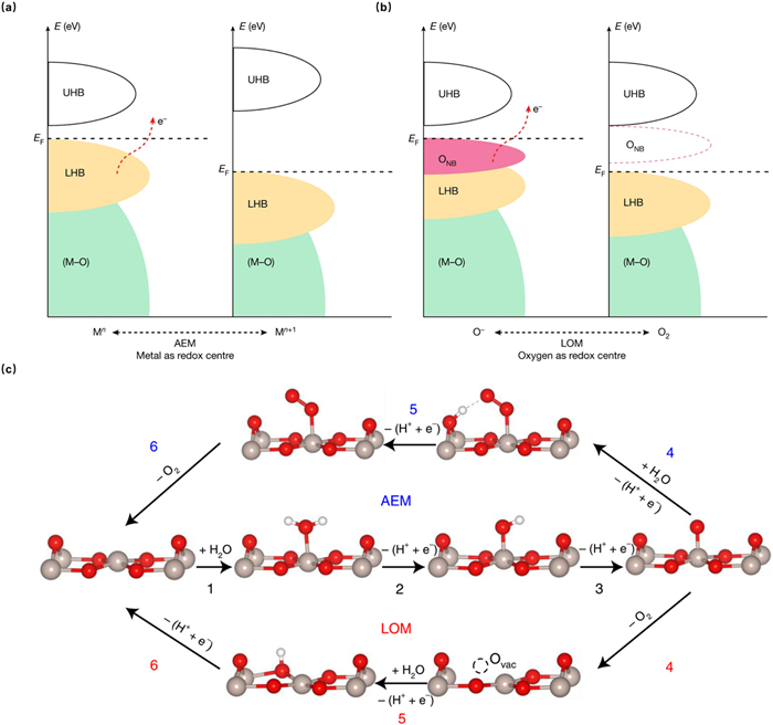
where the * represents the active sites on the catalyst surface, and the "ads" represents adsorbed state of intermediates, the "OLat" represents lattice oxygen, the "VO" represents oxygen vacancy. The above equations show two common mechanisms: adsorbate evolution mechanism (AEM, Eqs. 1–4 and lattice oxidation mechanism (LOM, Eqs. 1, 2 and 5–7, the vast majority of current literatures reporting OER are based on them. Both of them enable efficient electron transfer processes by changing the electronic states around the Fermi level. Typically, the OER undergoes AEM when there is a metal band around the Fermi level and electrons transfer occurs only through metal redox. Relatively, LOM would occur when there is an oxygen band around the Fermi level and electrons transfer through metal or oxygen redox (Figs. 1a and b) [39].
Figure 1
Figure 1.
Schematic illustration of OER routes. Traditional (a) AEM (metal redox and (b) LOM (oxygen redox routes. The bonding bands exhibiting oxygen character are denoted as (M–O). Owing to the on-site electron repulsion within the d orbitals, antibonding bands will split into empty upper and filled lower Hubbard bands (denoted as UHB and LHB, respectively). ONB shows the non-bonding oxygen state. Reproduced with permission [39]. Copyright 2022, Springer Nature. (c) Schematic illustration of AEM and LOM for OER on the RuO2 (110) surface. Grey, red and white balls represent Ru, O and H atoms, respectively. Reproduced with permission [41]. Copyright 2023, Springer Nature.
Both AEM and LOM start with two sequential deprotonation steps to form Oads in acidic media as Eqs. 1 and 2, followed by the selection of corresponding reaction path. For AEM, it will undergo Eqs. 3 and 4, with surface-adsorbed O further reacting with H2O to form OOHads and finally deprotonates to release O2. In contrast, LOM will undergo Eqs. 5–7, which involves the direct reaction of surface-adsorbed O with lattice oxygen to produce O2 and the concomitant formation of oxygen vacancies, which will then be filled with OHads by the deprotonation of adsorbed water [40–42]. The detailed process is illustrated by the OER of the RuO2 (110) surface (Fig. 1c) [41].
A critical difference between AEM and LOM is the source of oxygen molecules, which is derived from water molecules for the former and additionally originated from the lattice oxygen of oxides for the latter [35,43]. From the above equations, it can be seen that the conventional AEM mechanism involves multiple oxygen-containing intermediates, such as OHads, OOHads, Oads. The binding energies of the intermediates are linearly correlated with a scaling relationship of ΔGOOH = ΔGOH + 3.2 ± 0.2 eV [44], which means that it is not possible to individually modulate the binding energy of a single intermediate, leading to high theoretical OER potential of ~1.6 V. Obviously, the LOM mechanism does not contain OOHads intermediates, so it can break the above scaling relationship between the binding energies of the OER intermediates and reduce the energy barrier of the rate-determining step, thus resulting in a reduced overpotential [3,45,46]. Generally, LOM tends to occur in RuO2 and Ru-based perovskites due to their structural flexibility and weak Ru-O bonds, while for catalysts with more stable structures such as IrO2, AEM is more preferred [47,48]. Therefore, the activity of Ru-based catalysts is superior to that of Ir, but there is deficiency in terms of stability for Ru-based catalysts as the dynamic formation and accelerated migration of a large number of bulk-phase VO are usually accompanied by more severe metal dissolution and structural collapse [40,49–54]. In addition, the VO generated in the LOM further induce over-oxidation of Ru, and high-valent Ru dissolves in the electrolyte, which exacerbates catalyst deactivation. Therefore, vast methods with electronic and structural modulation such as doping with heteroatoms, constructing heterogeneous interfaces, optimizing carriers, phase and facet engineering are applied to mitigate metal dissolution, bulk lattice oxygen migration, structural reconstruction and catalyst dropping [55–59].
2.2
Evaluation protocols and techniques for the stability
Chronopotentiometry (CP), chronoamperometry (CA), accelerated stress test (ATL), stability-number (S-number), activity-stability factor (ASF), etc. are usually used to evaluate the stability of catalysts [60–65]. For CP tests, the current density of the electrode is kept at a constant value such as 10 mA/cm2, then the variation of overpotential is measured as an indicator to estimate the durability of catalysts. The increase in overpotential during the testing process corresponds to performance degradation [66,67]. Besides, CA is another reasonable method to assess the stability [68]. A constant potential is applied to the electrode and the stability is then evaluated by comparing the retention of the current [69]. AST is also a common employed approach by switching the potential between low and high value for a period of time and measuring the retention of activity. It can simulate the frequent start-up and shut-down process of practical PEMWE according with the actual situation [70]. Additionally, in order to establish a bridge between activity and catalyst dissolution, Geiger et al. introduced the S-number defined as the ratio between the amount of evolved oxygen and dissolved metal atoms in electrolyte. The S-number is independent of the surface of catalysts, amount of active sites and catalyst loadings, thus it can elucidate the intrinsic stability. The higher the number, the more stable the catalysts [33,34]. Similarly, the ASF defined as the ratio between the rate of oxygen production and metal dissolution is also applied as a metric to describe the stability [71]. Compared with the CP, CA and ATL, dissolution of metal cations is regarded as the sole catalyst degradation mechanism in the ASF and S-number. Nevertheless, participation of lattice oxygen, catalyst particles dropping and structural reconstruction are also related with the attenuation of activity [68]. Therefore, using a single dimension is not appropriate to describe the stability of catalysts precisely, and a cooperation of multidimensional approaches should be considered comprehensively.
During the process of OER, surface reconstruction and electron transfer caused by strong oxidation and corrosive acidic environment are accompanied by water electrolysis [72]. The consequential variation of atomic rearrangement and electronic state are closely related to the stability of catalysts. Therefore, many structural characterization techniques have been introduced to evaluate the durability [73,74]. For example, the X-ray diffraction (XRD), transmission electron microscopy (TEM) and X-ray photoelectron spectroscopy (XPS) images of the catalysts pre- and post-OER can be analyzed to illustrate the changes in crystallinity, surface morphology and electron distribution of the catalysts, which can reflect the stability. Liu et al. reported a trace sulfur doped RuO2-based nanosheet with long-term stability in acidic OER. To further prove the superb stability, many ex situ methods such as Ru 3p and O 1s XPS, TEM, high-angle annular dark-field scanning transmission electron microscopy energy-dispersive X-ray spectroscopy elemental mappings (HAADF-STEM-EDS), inductively coupled plasma (ICP) were performed for the catalysts before and after stability test, and almost no change in chemical valence, morphology, phase and element distribution could be detected [75–77].
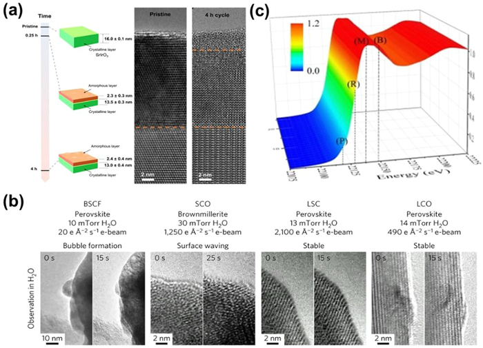
Moreover, by the virtue of in situ and Operando technology, researchers can additionally characterize the dynamic and instantaneous variation aforementioned. Elucidating the kinetic process of electrocatalysts at the electrode-electrolyte interface precisely is the precondition to deeply understand its degradation mechanisms but traditional ex situ techniques are unable to obtain sufficient and consecutive information. Thus advanced in situ and Operando tools are furtherly applied to provide critical understanding for the design of highly stable OER catalysts [78]. Suntivich et al. [79] investigated the surface crystalline-to-amorphous evolution of SrIrO3 during potential cycling (Fig. 2a) by using quasi in situ identical location transmission electron microscope (IL-TEM). This phase reconstruction is confirmed to be related with the decreased stability due to the promoted dissolution of active sites and structural collapse. Shao-Horn and coworkers detected the structural oscillations caused by the bubble generation and collapse using in situ time-resolved environmental transmission electron microscope (ETEM) (Fig. 2b) [80]. In addition to microscopy techniques, in situ and Operando X-Ray techniques are also widely utilized to investigate the evolution process and the degradation mechanism of the catalysts. For example, Operando X-ray absorption near-edge structure spectroscopy (XANES) was performed to analyze the electronic state of sodium-decorated amorphous/crystalline RuO2 and found there was almost no change on the Ru K-edge XANES spectra in the process of OER (Fig. 2c), which confirmed the excellent stability resulted by the introduction of sodium element [81].
Figure 2
Figure 2.
(a) Visual summary of the X-ray thicknesses of amorphous IrOx layer and cross-section transmission electron microscopy (TEM) images of the pristine SrIrO3 film after 4 h of potential cycling between 1.05 V and 1.75 V versus RHE. Reproduced with permission [79]. Copyright 2021, Springer Nature. (b) ETEM images of structure oscillation in perovskite oxides. Reproduced with permission [80]. Copyright 2016, Springer Nature. (c) 3D plot of operando Ru K-edge XANES spectrum of amorphous/crystalline RuO2. Reproduced with permission [81]. Copyright 2021, Wiley-VCH.
The degradation mechanisms of Ru-based catalysts have been the research focus for acidic OER electrocatalysis, which are categorized into four aspects in this paper, including dissolution of Ru ions, lattice oxygen participation, reconstruction of catalysts and peeling of catalysts, which will be described in the following sections. However, it should be noted that they do not act alone and have an impact on each other, and in high potential corrosive environments, one degradation usually leads to the occurrence of several others. For example, the oxygen vacancies induced by catalysts undergoing the LOM mechanism can aggravate the dissolution of Ru particles thereby bringing about structural collapse, catalyst peeling from the carrier, and other problems [82]. Therefore, it is necessary to consider the stability of Ru-based catalysts from multiple perspectives.
2.3.1
Dissolution of ruthenium ions
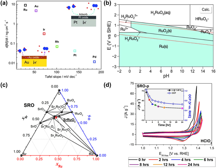
It is found that the onset OER potential is always accompanied by the dissolution of active sites, which is related to the nature, morphology, structure and oxidation state of noble metals [83]. Mayrhofer et al. [84] investigated the dissolution of catalysts under acidic OER environment by scanning flow cell/inductively coupled plasma mass spectrometry (SFC/ICP-MS) and established a correlation between stability and the Tafel slope for different noble metals (Fig. 3a). Among them, Ru with the lowest Tafel slope exhibits the least stability and the dissolution rate of RuO2(110) is 4.4 mL/h and 1.5 mL/h at 1.8 VRHE [85] and 1.6 VRHE in 0.05 mol/L H2SO4, respectively [86].
Figure 3
Figure 3.
(a) Correlation between stability and the Tafel slope for the OER for the noble metals. Reproduced with permission [84]. Copyright 2014, Wiley-VCH. (b) Calculated Pourbaix diagrams of RuO2 OER catalysts that resemble closely the experimental Pourbaix diagrams. Reproduced with permission [87]. Copyright 2020, Springer Nature. (c) Sr, Ru, and O phases computed using DFT calculations. Black and red dots represent thermodynamically stable phases and unstable phases, respectively. (d) Chemical stability of SRO in contact with electrolytes. CV at 10 mV/s was executed at 0, 2, 4, 6, 8, 12, and 24 h after the initial contact with the synthetic air saturated electrolyte without agitation in HClO4. Insets show the decrease of the current density at 1.45 VRHE for every time interval (indicated by colored dots in the black line) and the OCP collected during those contact periods (hollow blue dots in the blue line). Reproduced with permission [92]. Copyright 2017, American Chemical Society.
The Pourbaix diagram of RuO2 is shown in Fig. 3b [87], from which the changes of the oxidation state for Ru at full pH and applied potential can be found. Metal Ru and RuO2 are considered to be thermodynamically stable. However, potential-induced dissolution would occur in the electrolyte during OER [88]. Although the high-valent Ru obtained by oxidization can exhibit higher OER activity [55], due to the flexible redox state of Ru-based catalysts, they will not form thermodynamically stable oxides during the generation of O(H) ligands or oxidized lattice oxygen, but tend to dissolve as H2RuO22+ and H2RuO5 in acidic environment with increased anodic potential. It has been suggested that the over-oxidation of Ru-based catalysts in acidic electrolyte is mainly caused by lattice oxygen oxidation, which means the generation of oxygen vacancies would expose more surface Ru atoms during OER that are susceptible to over-oxidation to produce high-valence Ru oxides [29,68,89–91]. In addition to VO-induced dissolution, vacancies generated with the dissolution of other metal ions in multivariate Ru-based catalysts will also exacerbate the peroxidation of Ru. It has been reported that Sr-ruthenium oxides (SRO) films have extremely high OER activity whether in acidic or alkaline environment and exist many thermodynamically stable phases (Fig. 3c) [92]. However, it exhibits poor stability in acidic OER processes, and this trend can be seen in Fig. 3d, which clearly demonstrates the rapid decay of SRO in acidic environment by CV and OCP curve. It has even been reported to lose more than 85% of its initial activity after 20 consecutive cycles in acid. The main reason for the poor stability is the conversion of Ru4+ into Run>+4 at high potential (above 1.3–1.4 V) following the dissolution of Sr leading to perovskite decomposition, thereby giving rise to the collapse of mixed oxide structure.
2.3.2
Lattice oxygen participation
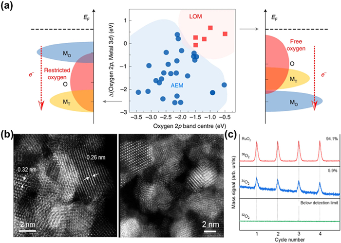
OER has two different pathways, the conventional AEM without participation of lattice oxygen and the LOM that most Ru-based catalysts prefer with lattice oxygen serving as active sites. The Ru–O covalency is the key factor of LOM-based catalysts. When the covalency is strengthened, an increased hybridization between Ru 4d and O 2p appeared. At this time, electrons can transfer from oxygen to metal cations during OER, causing a redox reaction. The reduced oxygen has higher degrees of freedom thus is prone to release from the lattice accompanied with the formation of oxygen vacancy. It is worth noting that the O 2p center should be high enough, otherwise the escape of O from lattice would be restrained (Fig. 4a) [93]. Due to the involvement of lattice oxygen, the scaling relationship is broken up, leading to an elevation in OER activity [72].
Figure 4
Figure 4.
(a) An illustration of how the O 2p band centre, and the relative band centres between O 2p and active metal 3d, co-regulate the reaction mechanism of OER on spinel oxides. Reproduced with permission [93]. Copyright 2020, Springer Nature. (b) HAADF-STEM images of pristine RuO2 and after stability test for 20 h. Reproduced with permission. (c) Isotope-assisted operando differential electrochemical mass spectrometry (DEMS) signals for 36O2, 34O2 and 32O2 from the reaction products for Re0.06Ru0.94O2 and RuO2 catalysts in H218O aqueous sulphuric acid electrolyte. Reproduced with permission [95]. Copyright 2023, Springer Nature.
However, lattice oxygen participation in LOM will decrease the stability of catalysts compared with AEM. Notably, a reversible oxygen vacancy refilling process would happen spontaneously in the framework of LOM. Rong et al. discussed this refilling phenomenon in perovskite and found that vacancies are thermodynamically unstable thus the ambient O in electrolyte would be prone to fill the vacancies [51]. However, the rate of refilling is lower than that of generation, hence adjacent unsaturated coordinated metal cations dissolve quickly in the electrolyte. Therefore, the formation of oxygen vacancies would destroy the structure of catalysts and reduce its corrosion resistance in acidic and oxidized environment [51,55,94]. To further confirm this influence on catalysts, the structural reconstruction of RuO2 was researched after long-term OER tests and the obvious transformation from crystalline to amorphous phase could be observed (Fig. 4b). This difference of structure originates from the escape of lattice oxygen and collapse of structure, which is further demonstrated by isotope labeling method due to the prominent signals for 36O2 from reaction product (Fig. 4c) [95]. In addition, with the deterioration of catalyst structures, its affinity with support will also be affected due to the occurrence of more flexible structure and bubbles, thus peeling of catalysts from supports is inevitable, leading to the rapid activity decline [88]. Paoli et al. observed the morphological alteration of the as-deposited Ru under OER condition by electrochemical scanning tunneling microcopy (EC-STM), and found that with the increase of potential, Ru particles would disappear in the image, which meant catalysts dropping from the support material due to the more deteriorating Ru-O structure along with massive lattice oxygen participation during OER [96]. Consequently, improving OER activity by LOM at the expense of stability needs more consideration, and it is urgent to set up a suitable tradeoff between stability and activity.
2.3.3
Reconstruction of catalysts
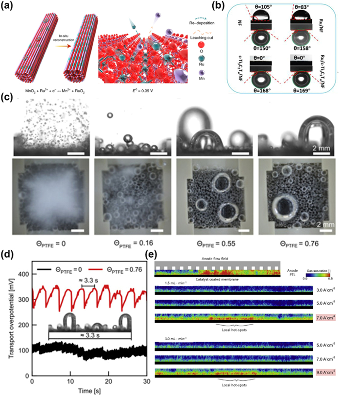
Catalyst reconstitution typically refers to spontaneous changes in terms of geometry, crystalline phase, components and electronic structures at a given anode potential [97]. And metal catalysts might form metal oxides or (oxy)hydroxides during the OER process with a high oxidation potential. This process can be verified by physicochemical analysis of the catalysts before and after the reaction. Lee et al. [49] used time-dependent elemental analysis method and found that Ru/MnO2 underwent an in-situ dynamic cation exchange reaction during the OER, triggering the reconfiguration of Ru atoms into an ordered array of RuO2 (Fig. 5a). Most of the reconstructions facilitate the generation of new superior active sites, resulting in increased activity [98,99]. But one of the great challenges for surface reconstruction is the high rate of catalyst dissolution thus leading to catalytic instability, which is known as "transient dissolution mechanism". Cherevko et al. [84] tested the dissolution profiles of Ru, Pt, Ir and found transient dissolution of Ru-based catalysts can be observed at the potential lower than OER potential, suggesting that the structural decay of the catalysts is not only caused by the oxygen evolving process, but also related to the oxidation and reduction process on their surfaces. The dissolved atoms may redeposit on larger particles in order to reduce the surface free energy, which is the so-called Ostwald ripening [100], leading to a rapid increase in particle size and catalyst deactivation. Among the precious metals, Ru is relatively more susceptible to agglomeration due to its high cohesive energy [101].
Figure 5
Figure 5.
(a) Schematic illustration for the in-situ reconstruction process of Ru/MnO2. E0 represents the standard redox potentials at 298.15 K and a pressure of 1 atm. Reproduced with permission [49]. Copyright 2021, Springer Nature. (b) The contact angles of water droplets and underwater contact angles of gas bubbles on NF, Ru/NF, c-Ti3C2Tx/NF, and Ru/c-Ti3C2Tx/NF electrodes [109]. Copyright 2021, Elsevier. (c) Side views and top views of oxygen bubbles at 400 mA/cm2. (d) Time transition of transport overpotential at 400 mA/cm2 [110]. Copyright 2021, Elsevier. (e) Gas distribution radiographs through the anode PTL during operation. The top border is the PTL-Flow field interface and the bottom border is the CL-PTL interface. Reproduced with permission [111]. Copyright 2020, Elsevier.
To prevent the diffusion, overoxidation and aggregation of active sites in OER, the catalysts are usually anchored on a conductive substrate, and the interaction between substrates and catalysts can also modulate the electronic structure of the active site and further optimize their performance [102]. However, catalyst dropping from substrate due to the extreme reaction conditions in acidic OER is one of the prime reasons of performance decay. Carbon-based materials and transition metal oxides are the most widely used supports for catalysts, yet they tend to corrode in acidic and oxidized environment, leading to peeling of active sites. As the potential increases, deterioration of the substrates becomes more serious, which critically hinders their long term usage. For carbon materials, they are likely to be oxidized by water to form CO at a lower potential, and further oxidized to CO2 when the potential is greater than 0.9 V [103–105]. For transition metal oxides, it is arduous to make a trade-off between conductivity and stability, such as CeO2, which have excellent conductivity, are prone to dissolve in acidic environment, while other oxides with intensive resistance to corrosion, such as TiO2, are limited by their sufficient electron transfer ability [106].
In addition to substrates corrosion, catalysts would also drop from the electrode due to the attack of massive bubbles generated in OER. During the OER, O2 produced from active sites would diffuse through the electrode interface [107]. However, due to the limited solubility, bubbles prefer to emerge on the heterogeneous interface with lower forming energy barrier and are evolved via the sequent steps of nucleation, growth and detachment. The active sites could be blocked undesirably by numerous bubbles, accompanied by mechanical force attacking to the connection between catalysts and electrodes or substrates, causing the attenuated durability [108]. To establish the relationship between bubble parameters and stability of catalysts. Kong et al. analyzed the surface wetting ability and spillover rate of gas bubbles, finding that the underwater bubble contact angles of Ru/NF is 158°, lower than that in Ru/c-Ti3C2Tx/NF (169°), and the diameter of bubble decreased in the order of Ru/NF (120 µm) > Ru/c-Ti3C2Tx/NF (60 µm) (Fig. 5b) [109]. A lager diameter and smaller contact angles implies more tendency in detaching and more violent attack. The impact of bubbles on stability varies with different current density. At a low current density, the rate of bubble generation is small and negligible. In contrast, it would be more intense at larger current density and become the dominant factor of catalyst deactivation. It is clear that electrodes with larger bubbles show higher overpotential and overpotential fluctuation in Figs. 5c and d [110]. Therefore, in the commercial PEMWE, the effect of bubbles should not be neglected due to the complicated assembles and large working current. The influence of bubbles on the PEMWE was investigated systematically and the bubbles were proposed to travel from catalyst layers (CL) to porous transport layers (PTL) and then carried away by the water flow in the flow field (Fig. 5e) [111]. During the whole process, a large accumulation of bubbles blocks the liquid-gas transport channel, and the stress generated due to the detachment of bubbles can attack the assembles, causing structural oscillation and performance decay. Thus in the case of dynamic loads, bubble accumulation must be taken into consideration. Besides, catalysts can peel from electrode due to the deterioration of ionomers as well. Electrocatalysts should not be applied directly for electrocatalysis, unless they are uniformly loaded on the electrode surface. In order to guarantee enough interaction and avoid the catalysts detachment, ionomers consisting of polymers and ionic groups are employed as an important component in electrocatalytic reaction [112–114]. Nafion is widely used in such region because of its good proton exchange property and excellent ionic conductivity [115,116]. Nevertheless, Nafion would degrade continuously in oxidized and acidic conditions. The chemical degradation of ionic groups may be caused by the nucleophilic attack of water, oxidation of oxygen radicals and massive bubbles in PEMWE, and the subsequent collapse of ionomer skeleton structures and weak interactions lead to the catalysts peeling [117,118]. As a result, the number of active sites on the electrode decreases substantially, causing a severe activity degradation [88].
3.
Strategies to improve the stability of Ru-based electrocatalysts
As mentioned above, Ru-based catalysts are considered as promising material to meet the practical application of PEMWE due to their excellent OER activity in acidic conditions. However, there is still a gap in stability between the actual level and industrial requirements. To address this challenge and promote their further commercialization, many strategies have been attempted to enhance their durability, including heteroatom doping, phase and facet engineering, introduction of heterojunction and support optimization [56,83,119–121]. In this section, we summarize the recent research progress and hope to provide some inspirations for the rational design of more stable Ru-based catalysts.
3.1
Heteroatom doping
Heteroatom doping, as a prevalent method of material modification, can not only enhance the activity of Ru-based catalysts, but also improve their stability remarkably [57]. Lots of researches have demonstrated that cations/anions doping can modulate the electronic structure, chemical valence, and even reaction path of catalysts, therefore suppressing the over-oxidation of active sites, reducing the participation of lattice oxygen, finally enhancing their stability [3,119].
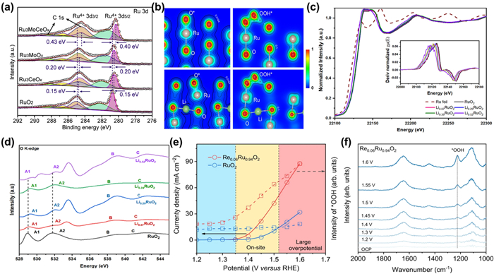
By introducing additional elements, electron transfer between Ru atoms and heteroatoms will occur due to their different electronic properties such as electronegativity, work function, thus modulating the electronic structure of the Ru sites. The ternary RuMoCeOx with different Ru/Mo/Ce ratios through the co-doping of Mo and Ce into RuO2 was fabricated by pyrolysis [57]. Compared with commercial RuO2 which decays quickly after several hours OER test at 100 mA/cm2, RuMoCeOx shows negligible change after 100 h test, manifesting its robust stability. The negative shift of Ru 3d5/2 peaks for RuMoCeOx compared with other samples in Fig. 6a shows that the co-doped Ce and Mo act as electrons donators and transfer electrons to Ru in RuMoCeOx. Therefore, Ru exhibits higher electron density, making it more difficult to be over-oxidized during OER and enhancing its resistance of dissolution. In addition to transition metal cations, alkali cations such as Li+ and Na+ can also be introduced to promote the stability of Ru-based catalysts. Qin et al. reported an electrochemical lithium intercalation method to form Li0.52RuO2 solid solution to elevate the activity and durability of RuO2, which reached an ultralow overpotential of 156 mV at 10 mA/cm2 in 0.5 mol/L H2SO4 and exhibited robust durability during 70 h chronopotentiometry test [122]. The intercalation of lithium results in a coordination environment of Ru-O-Li and Li can serve as a donator to transfer electrons to O (Fig. 6b). Hence less electrons transfer from Ru to O, leading to a longer Ru-O bond length and a decline in the valence state of Ru, enhancing its dissolution resistance. Besides, the doping of non-metallic elements can also realize long-term operation for Ru-based catalysts. Liu et al. found that the limited durability of Ru-based oxides can be improved by pre-trapping RuCl3 precursors within an organic cage compound with functional groups containing silicon, which lead to well carbon-coated Si-RuOx particles (Si-RuOx@C) after calcination [123]. Differentiating from the conventional RuO2, Ru is bonded to one Si and three O atoms in Si-RuOx@C, implying that O in Ru-O is partially replaced by Si. Since the weaker electronegativity of Si than O, the average electron density of Ru in Si-RuOx@C is significantly higher than that in RuO2, thereby suppressing the over-oxidation of Ru and improve its corrosion resistance. The overpotential of Si-RuOx@C at 10 mA/cm2 merely increases by 10 mV after 27,000 CV cycles. ICP test manifests that <2% Ru is lost, corroborating the preeminent stability.
Figure 6
Figure 6.
(a) XPS spectra of Ru 3d spectra for RuO2, Ru3CeOx, Ru3MoOx, and Ru3MoCeOx [57]. Copyright 2023, Elsevier. (b) The charge density distribution of the O* and OOH* absorbed on the (110) surface of RuO2 (Up) and Li0.5RuO2 (down). (c) Normalized Ru K-edge X-ray absorption near-edge structure (XANES) spectra. Inset: the first derivatives of the Ru K-edge XANES spectra of RuO2 and LixRuO2. (d) O K-edge soft XAS of LixRuO2 and RuO2. Reproduced with permission [122]. Copyright 2022, Springer Nature. (e) Potential dependence of band intensity of characteristic vibration adsorption of surface-adsorbed *OOH. (f) In situ ATR-SEIRAS spectra for Re0.06Ru0.94O2 during multi-potential steps. Reproduced with permission [95]. Copyright 2023, Springer Nature.
Selective regulation of the OER path through elemental doping can also enhance the durability Ru-based catalysts [122]. Owing to the involvement of lattice oxygen, the catalyst structure is disrupted and deteriorated, thus the dissolution rate of the catalysts is accelerated, resulting in poorer stability for LOM than AEM. Therefore, transferring the catalytic pathway from LOM to AEM and inhibiting the escape of lattice oxygen can effectively enhance the durability of Ru-based catalysts in acidic OER [83]. As mentioned above, the Li–doped RuO2 regulates the electronic structure of Ru to enhance its stability [122]. However, the effect of suppressing the participation of lattice oxygen should not to be neglected. The absorption edge position in the normalized Ru K-edge XANES has a positive shift for LixRuO2 relative to pure RuO2 (Fig. 6c), indicating that the structure of Ru-O-Li can reduce the covalency of Ru-O, so that the participation of lattice oxygen would be suppressed (Fig. 6d). What is more, Wang et al. reported an ingenious strategy to stabilize RuO2 with interstitial C through the joint evaporation of Se and combustion of C [124]. It maintains the activity without any obvious decay after 50 h test under highly acidic conditions at current densities of 20 and 50 mA/cm2, substantially surpassing the commercial RuO2 without additional doping. DFT calculation indicates that the dissociation energy of *O (ΔGO) for RuO2 with interstitial C is 0.8 eV higher than undoped RuO2, representing the lattice oxygen atom need more energy to dissociate. Besides, the elongated Ru-O gap owing to the C-O from introduction of interstitial C can enhance the dissolution resistance. Jin and co-workers changed the OER pathway of RuO2 with Re dopants in Re0.06Ru0.94O2, leading to a high S-number of 4.0 × 10⁶noxygen/nRu and negligible attenuation after a continuous 200 h test at 10 mA/cm2 [95]. Different from the static electron redistribution in traditional doping, the introduction of Re enables dynamic transfer of electrons (Fig. 6e). At 1.35-1.5 V, Re dopants accept electrons from Ru, oxidizing and activating Ru sites. At a high potential region of 1.5–1.6 V, electrons transfer from Re back to Ru to prevent Ru sites from over-oxidization and maintain stable catalytic performance. In situ attenuated total reflectance surface-enhanced infrared absorption spectroscopy (ATR-SEIRAS) further determines the actual OER pathway on Re0.06Ru0.94O2 though a distinct absorption peak at 1224 cm−1 attributed to the O-O stretching of *OOH (Fig. 6f). The peak intensity increases linearly when the potential becomes higher, confirming the typical AEM pathway. Relatively, RuO2 demonstrates the unidentifiable *OOH with weaker intensity after OER on-site, which affirms the LOM pathway.
3.2
Phase and facet engineering
Solid materials with different atomic arrangements (i.e., crystalline phases) usually have different electronic structures, which not only determine the strength of adsorption of reaction intermediates, but also affect the strength of chemical bonds and allotropic environment, which are related to the stability of the catalysts [125–130].
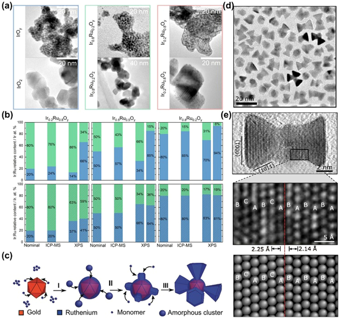
It has been shown that Ru in the face center cubic (fcc) phase is more stable than Ru in the hexagonal close-packed (hcp) phase by exposing more low index crystalline surfaces, and that rutile phase RuO2 is more stable than metallic Ru [131–134]. However, in general, the increase in stability is accompanied by a decrease in activity, so it is of great value to balance the relationship between catalytic activity and stability. Cherevko et al. [135] prepared structurally well-defined IrxRu1-xO2 nanoparticles by the surfactant-free and rapid flame spray pyrolysis (FPS) method to investigate the composition- and phase-dependence for OER catalysts. The as-prepared nanoparticles (IrxRu1-xOy) present an amorphous coral-like structure with a hydrous Ir-Ru oxide phase, which transforms to a rutile-type IrxRu1-xO2 during post-synthetic thermal treatment and Ir selectively biases toward its topmost surface (Fig. 7a). Since RuO2 in rutile phase shows better durability compared to amorphous Ru oxides, IrxRu1-xOy presents a higher OER activity and worsened stability due to the unstable IrⅢ/RuⅢ (oxy)hydroxides, whereas rutile-type IrxRu1-xO2 has a lower activity but improved stability (1000-fold lower Ir/Ru dissolution) as demonstrated by the almost unchanged nanoparticle morphologies and Ir: Ru surface compositions before and after cycling (Fig. 7b).
Figure 7
Figure 7.
(a) Transmission electron microscopy images of the as-prepared (top panel) and post-calcined (bottom panel) FSP IrxRu1–xOy nanoparticles. (b) Relative Ir: Ru content (in at%) for as-prepared (top row) and post-calcined (bottom row) FSP IrxRu1–xOy nanoparticles, calculated from the theoretical Ir: Ru ratio targeted during synthesis, the RSF-normalized Ir 4f: Ru 3p3/2 XPS weighted component analysis, and ICP-MS data. The ICP-MS data column denotes the NP surface-normalized Ir: Ru relative content after ICP-MS data integration. For XPS data, the first data column corresponds to pristine catalysts, and the second data column corresponds to OER-tested catalysts. Labels: Ir (blue) and Ru (green). Reproduced with permission [135]. Copyright 2021, American Chemical Society. (c) Growth mechanism of the Au-Ru branched NPs. Reproduced with permission [23]. Copyright 2018, John Wiley and Sons. (d) Low resolution TEM image of Pd–Ru branched nanoparticles. (e) HRTEM image of a linear bipod nanoparticle and FFT (inset) of a Ru branch viewed down the hcp 〈0110〉 zone axis with the branch surface indexed to {0001} and {1011} facets (top panel). Magnified HRTEM image of the black box in top panel and corresponding model showing the Pd-core Ru-branch interface with ABCABC and ABABAB stacking of close packed planes in the fcc-Pd core and hcp-Ru branch, respectively. The matched transition from fcc to hcp stacking is shown by the red dotted line (bottom panel). Reproduced with permission [137]. Copyright 2018, American Chemical Society.
The crystal surface also has a large effect on the stability of catalysts. High index surfaces with more steps, kinks and defects are more active in catalysis owing to the more active sites and lower coordinated numbers. However, due to the defects and uncoordinated environment, these surface atoms are prone to be over-oxidized and dissolution, leading to a worse stability [134]. Gloag and co-workers [23,136,137] demonstrate that Ru nanoparticles with a low-index facets actually exhibit higher OER stability in acidic electrolytes compared to non-faceted nanoparticles. They developed a synthetic method to obtain Ru branches with low-index facets exposed (Fig. 7c) at low ratios of dodecylamine (DDA) surfactant to Ru precursor. The TEM image in Fig. 7d shows the successful synthesis of Pd-Ru branched nanoparticles, and the branches are terminated by low index {0001} and {1011} facets of a hcp crystal structure (Fig. 7e), resulting in a hexagonal pyramid shape. The selective exposure to {0001} {1011} planes for Au-Ru and Pd-Ru branched nanoparticles can significantly inhibit the dissolution of Ru species, which are superior to other amorphous monometallic Ru. Marković et al. [82] prepared strontium ruthenate (SrRuO3) single-crystal thin films (SRO(hkl)) with good OER properties on Nb-doped SrTiO3 single-crystal substrates and found that the activity of the SRO films increases in the order (001) < (110) < (111). They conclude that both stability and activity are controlled by the potential-induced transformation of stable Ru4+ to unstable Run>4+, which is determined by the co-decision of electronic effects (surface energy) and morphological effects (surface defects). Because the SRO (001) surface is the least defective surface, it has the lowest activity. But it is more stable due to the non-polar feature and the reduced surface energy.
3.3
Heterostructure building
In heterojunction catalysts, electrons can be rearranged at the heterojunction interface, and the lattice strain will also occur at the heterogeneous interface of two crystals with mismatched lattice constants. Therefore, the activity and stability of catalysts would be optimized through electronic structure effects and surface structural effects [139]. For Ru-based catalysts, their stability can be improved through heterojunction in two ways. Firstly, another group of components transfer electrons to Ru through the heterogeneous interface, thus inhibiting the transition of Ru to higher valence state and preventing it from dissolving in acidic media [139,140]. Secondly, heterojunctions like core-shell structure can inhibit the dissolution of Ru [141,142].
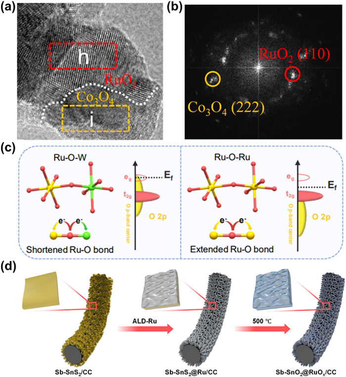
There are various strategies for the synthesis of heterostructures, including seed crystal growth, hydrothermal synthesis, solid-phase synthesis, chemical reduction, and replacement methods [143]. Crystal synthesis and solid-phase synthesis are easy to control the morphology and particle size of heterojunctions; hydrothermal method can obtain high crystallinity heterojunctions; chemical synthesis and replacement method can introduce target elements into heterojunctions [144]. Ru-based heterojunction catalysts can also be synthesized with these methods, and different synthetic strategies are chosen according to different needs. Liu et al. [145] synthesized a Ru/RuO2-Co3O4 heterojunction (Figs. 8a and b) by thermal treatment of Ru3+ coating ZIF-67 in air using a cobalt-based zeolite imidazolate skeleton (ZIF-67) as a sacrificial template. The heterojunction exhibits excellent catalytic activity and stability toward OER in acidic media (0.1 mol/L HClO4) with 226 mV overpotential at 10 mA/cm2 and small increase in overpotential after 19 h continuous testing. The excellent stability of Ru/RuO2-Co3O4 comes from two aspects: (1) After annealing, the catalyst surface is covered with a thin carbon layer, which can effectively protect the catalyst from corrosion; (2) Co3O4 adjacent to RuO2 provides electrons to reduce the valence state of Ru and weaken the Ru-O covalency, which greatly inhibits the dissolution of Ru thus enhancing its stability. Peng et al. [146] fabricated robust inter-doped tungsten-ruthenium oxide heterostructure [(Ru-W)Ox] by a solution combustion and calcination. The inter-doped (Ru-W)Ox heterostructure exhibits an overpotential of 170 mV at 10 mA/cm2 and excellent stability up to 300 h in acidic electrolytes. More impressively, PEMWE can be stabilized at 0.5 A/cm2 for 300 h by using (Ru-W)Ox as the anode, demonstrating its potential for practical applications. Its excellent stability stems from the high-valent W species, which alleviates the distorted octahedral RuO6 structural unit by shortening the Ru-O bond length during the OER process to improve the stability of catalysts (Fig. 8c).
Figure 8
Figure 8.
(a) HRTEM image of Ru/RuO2-Co3O4. (b) FFT pattern corresponding to region in (a). Reproduced with permission [145]. Copyright 2023, American Chemical Society. (c) Schematic illustration of the regulation of the Ru-O bonding environment in RuOx and (Ru-W)Ox [146]. Copyright 2023, Wiley-VCH. (d) Schematic illustration for the in situ synthesis of Sb-SnO2@RuOx on CC [141]. Copyright 2023, American Chemical Society.
Core-shell structure, as an unique heterostructure with the main active site located on the exposed outer surface component, have been widely designed for Ru-based catalysts [147]. When Ru or RuOx are used as shells, they mainly act as active sites for OER, and usually the nuclear materials transfer electrons to the shells in order to inhibit the dissolution of active sites brought about by excessive oxidation of Ru/RuOx. Bera et al. [141] prepared in situ crystallized antimony-doped tin oxide (Sb-SnO2@RuOx) core-shell structured nanosheets (NSs) (Fig. 8d) with enhanced OER stability. The catalyst was synthesized by atomic layer deposition (ALD) of a Ru conformal films on Sb-doped tin sulfide NSs followed by controlled heat treatment. Its excellent stability not only comes from the strong interaction between components resulting from in situ crystallization, but also the core-layer 2D architecture of Sb-SnO2 restricting the valance transformation from Rumetal to Rux+. When Ru or RuOx act as the nucleus, it generally captures electrons from the shell structure to avoid its own dissolution and regulates the electronic structure of the shell layer to optimize the adsorption of reaction intermediates. Qiao et al. [89] constructed a Ru@IrOx core-shell structure with a highly strained Ru core and a partially oxidized IrOx shell. The relatively high-valence state of Ir in Ru@IrOx makes Ru less prone to be further oxidized into soluble species to protect Ru core, thus avoiding a significant loss of active sites.
3.4
Support optimization
As an excellent and impeccable support, it should have outstanding conductivity, prominent stability, rich specific surface area to disperse catalysts uniformly, and ability to regulate the electronic structure of catalysts appropriately [83]. Carbon-based materials are usually chosen as supports for electrocatalysis because of their high specific surface area and superior conductivity [104]. Nevertheless, in acid OER, the stability of carbon is not satisfactory due to the high operation potential caused corrosion. Besides, the actual oxidation potential of carbon not only depends on the elemental nature itself, but also correlates with its surface properties such as crystallinity, electron distribution and types of functional groups [83]. So tremendous efforts have been done to optimize it or try to find another suitable alternative like metal oxides [106].
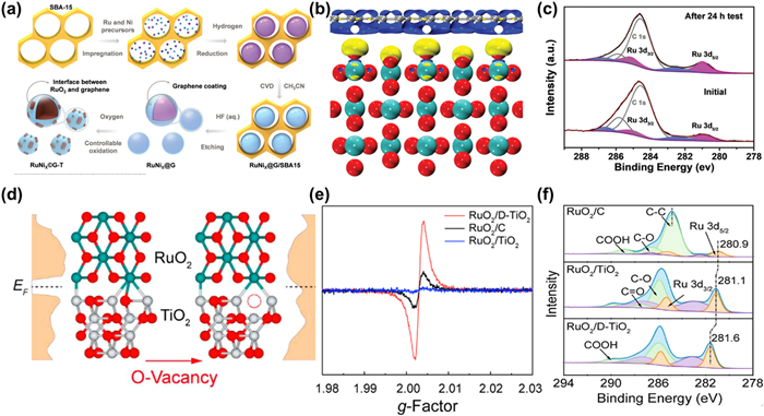
Optimizing the surface properties and constructing a robust catalyst-support interface is extremely effective to improve the corrosion resistance of carbon-based materials [55,75]. Cui et al. reported the electron-rich graphene encapsulated RuNi nanoparticles (RuNi2@G-T) via a controllable oxidation (Fig. 9a) [56]. On one hand, the presence of graphite shell can effectively inhibit the aggregation and detachment of metal particles during OER process, on the other hand, the electron-rich surface can enhance the corrosion resistance of the graphene under harsh acidic environment. In addition, the interaction between graphite and RuO2 results in electron rearrangement, causing more electrons transfer from C to Ru and simultaneously maintaining an electron-rich state of graphite, which prevents Ru atoms from over oxidation and dissolution, demonstrating a negligible change of chemical state and structure after dozens of hours of constant current chronopotentiometry test (Figs. 9b and c). Through heteroatom doping and modification, the poor stability of C-based materials can be significantly improved. Ultra-small Sn-doped RuO2 particles supported on the N-doped carbon polyhedral was synthetized using a simple impregnation method [148]. Compared with pure carbon, the introduction of N not only benefits the formation of porous carbon structures with relatively large specific surface, but also optimizes the electron rearrangement between C and RuO2. As a result, suitable adsorption strength with intermediates and enhanced corrosion resistance are obtained at the same time, which displays an ultra-stable performance after more than 150 h at 10 mA/cm2. In addition to mono-element doping, carbon materials co-doped with multiple elements have also been reported in the field of electrocatalysis, such as ORR, HER, including N, P co-doped carbon matrix, N, O-co-doped graphene nanorings-integrated boxes, B, N co-doped graphene [148–150]. However, the application of this multi-element doped C material as a substrate in Ru based catalysts for acidic OER is still limited and needs future research.
Figure 9
Figure 9.
(a) Schematic illustration of the preparation process for RuNi2@G-250 with interface between RuO2 and graphene. (b) Differential charge density at the interface Ru centers between RuO2 and graphene. Yellow and blue contours represent electron accumulation and depletion. (c) XPS spectra for RuNi2@G-250 supported on carbon fiber before and after 24 h stability testing. Reproduced with permission [56]. Copyright 2020, Wiley-VCH. (d) Schematic illustration of RuO2/TiO2 and RuO2/D-TiO2. (e) EPR spectra of RuO2/D-TiO2, RuO2/C, and RuO2/TiO2. (f) Core-level XPS spectra for C 1s + Ru 3d regions. Reproduced with permission [154]. Copyright 2022, American Chemical Society.
Apart from carbon materials, metal oxides or other compounds also attract great attention due to their excellent physical and chemical properties, and have been widely applied in electrocatalysis [152]. For example, TiO2 is considered as an ideal support owing to the high specific surface area and strong corrosion resistance in acidic environment. A defective RuO2/TiO2 heterostructure in situ growth on Ti mesh (D-RuO2/TiO2/TM) was reported and demonstrated slight change of overpotential after dozens of hour test [153]. The exciting durability is ascribed to the strong stability of TiO2 itself and the metal-support interaction induced electron transfer from TiO2 to RuO2, resulting in a decrease in the valence state of Ru and an improvement in over-oxidation resistance. Despite excellent stability, TiO2 shows unsatisfied activity due to the poor conductivity compared to carbon materials. Therefore, it is necessary to modify TiO2 to boost its electron transfer dynamics thus balancing the OER activity and stability. Wang et al. modified the electronic properties of TiO2 by introducing oxygen vacancies (D-TiO2) and dispersing RuO2 nanoparticles on it evenly (Figs. 9d and e) [154]. XPS results in Fig. 9f indicate that compared with ordinary TiO2, the one rich in oxygen vacancies can lead more electrons transfer from Ru to the neighboring Ti sites at the RuO2/D-TiO2 interface, achieving the electron redistribution and improving the adsorption energy between active sites and intermediates. Consequently, the inactivation resistance and electron transfer kinetics are optimized. A minimal voltage variation of 16 mV is observed for RuO2/D-TiO2 after 100 h of stability tests at 200 mA/cm2 in a PEM electrolyzer even at 80 ℃ under ambient pressure, confirming the possibility of improving both catalyst activity and stability simultaneously by support optimization. Heteroatom doping is also an available strategy to regulate the electron configuration of metal oxides. Huang et al. reported the tensile strained RuO2 nanorods growing on antimony-tin oxide (ATO) particles using the Co-hexamethylenetetramine metal-organic framework (Co-HMT) as precursor via fast-quenching method [58]. PEMWE using s-RuO2/ATO as the anode shows no significant decline even after 40 h due to the incorporations of ATO substrate. In addition to ATO, other heteroatoms doped tin oxide such as FTO (fluorine-doped tin oxide) and ITO (tin-doped indium oxide) also exhibit superior conductivity and are expected to be used for acidic OER in the future research [155,156]. Compared to metal oxide, other metal compounds like transition metal carbides are also regarded as promising substrates for acidic OER by virtue of their intriguing electron transfer dynamics and corrosion resistance [157]. The dependence of common transition metal carbides between stability in electrolytic solutions and pH was explored and the carbides of group VI transition metals showed a robust durability under a wide pH and electrochemical potential range. Furthermore, WC displays the largest region of stability at low pH through the CP and CV tests [158]. Based on the above experimental results, Sun et al. successfully anchored RuO2 particles on WC, achieving the electron transfer from WC to Ru atom and optimizing the surrounding electronic structure due to the strong metal-support interaction, which not only reduced the reaction barrier, but also prevented Ru sites from over-oxidation and dropping to realize the durable OER performance in acidic media [159]. Other transition metal carbides such as VC, TiC, TaC, have also been reported as promising support materials. Moreover, the modification of metal carbides, like N-doped WC, has demonstrate sufficient activity and stability as well in acidic OER and HER [160,161]. However, there are still few reports on metal compounds supported Ru based catalysts in such fields, and more efforts are needed to push the stability of catalysts to the next stage.
In order to visualize the activity and stability of a variety of Ru-based catalysts in acidic environment, Table 1 summarizes the OER performance of Ru-based catalysts reported in the previous literatures [56–59,89,95,122–124,141,145,148,154,161–179].
Table 1
Table 1.
OER performance of Ru-based electrocatalysts.
High performance acidic OER electrocatalysts plays a key role in realizing the wide application of PEMWE. Ru-based catalysts have excellent activity and relatively lower cost among the currently reported noble metal-based catalysts. The problem hindering their further commercialization is their limited stability. In this paper, four deactivation mechanisms of Ru-based catalysts are presented, including dissolution of ruthenium ions, lattice oxygen participation, reconstruction and peeling of catalysts. Based on the electronic effects (electron transfer between other components and Ru) and structural effects (the arrangement of atoms for Ru-based catalysts), four methods to improve the stability of Ru-based catalysts are summarized, in terms of heteroatom doping, phase and facet engineering, heterostructure building and support optimization. By improving the stability of Ru-based catalysts through the above-mentioned engineering without sacrificing their activity, we believe that Ru-based catalysts will be the key asset for acidic OER. Although great progress has been made in Ru-based electrocatalysts, there are still several problems for their further development.
First, more in-situ characterization techniques should be carried out. The reaction mechanism of OER which is an important guide for designing highly stable materials is still ambiguous. In recent studies, more and more experimental results have revealed that catalysts would undergo reconstruction during the reaction and dynamic chemical changes on the surface occur throughout the process, which would challenge the traditional mechanism based on the assumptions of well-defined electrode and electrolyte interface. Most characterization techniques can only show the state of catalysts before/after the reaction, and the active site may exhibit reversible structural changes during the OER process, so this cannot infer a complete dynamic degradation process. On the other hand, catalysts will inevitably be exposed to air before being transferred into overhead devices, so the detected surface structure is not completely realistic. In-situ characterization techniques of detecting the catalytic structure changes in a real-time manner are still scarce and more test techniques need to be upgraded to follow the changes in active sites during acidic OER.
Second, the disparity between laboratory test environment and industrial applications should be closed. The corrosion mechanism of catalysts is closely related to the current density, meaning that catalysts with stable performance in laboratory scale testing may not be stable under industrial operating conditions with high current densities. Anode catalysts are subjected to very harsh operating conditions in practical applications, including mechanical stresses formed by oxygen bubbles, as well as potential gas pockets in the porous structure of the catalyst layers, and localized hot spots due to high current densities or the resulting complexation of oxygen and hydrogen in the membrane. In addition, membranes, impurities, and ionomers will all have an effect on the stability of PEM-based electrolyzers. In particular, the stability of membranes is critical, as free radical intermediates such as hydroxyl (HO) would attack the backbone of the ionomer, leading to chain breakage, decompression, loss of functional groups and membrane thinning. Therefore, more research is needed to narrow the gap between laboratory scale and practical application of electrolyzers component design.
Third, descriptors on stability should be extended. Several existing descriptors for evaluating the stability of catalysts are mostly affected by their ECSA and loadings, and it is crucial to establish a unified benchmark for comparing the intrinsic stability of various catalysts, similar to S-number. Whereas in terms of the OER mechanism, the solvation of lattice oxygen by the LOM poses a great challenge to stability, and the strength of the Ru-O bond, the crystallinity of the materials, the vacancy formation energy, etc. can all be used as important indicators to evaluate their stability. The unification of these factors is of great significance for the design of stable Ru-based catalysts with high activity. There are fewer descriptors to comprehensively assess the stability of catalysts, which results in relatively homogenous stability tests and one-sided results, so it is also critical to establish and develop additional assessment metrics.
Declaration of competing interest
The authors declare that they have no known competing financial interests or personal relationships that could have appeared to influence the work reported in this paper.
Acknowledgment
This work was financially supported by National Natural Science Foundation of China (Nos. 22122202, 22072051, 21972051).
L. Li, J. Zhou, X. Wang, et al., Adv. Mater. 35 (2023) 2302966. doi: 10.1002/adma.202302966
[179]
H. Yan, Z. Jiang, B. Deng, Y. Wang, Z.J. Jiang, Adv. Energy Mater. 13 (2023) 2300152. doi: 10.1002/aenm.202300152
Figure 1
Schematic illustration of OER routes. Traditional (a) AEM (metal redox and (b) LOM (oxygen redox routes. The bonding bands exhibiting oxygen character are denoted as (M–O). Owing to the on-site electron repulsion within the d orbitals, antibonding bands will split into empty upper and filled lower Hubbard bands (denoted as UHB and LHB, respectively). ONB shows the non-bonding oxygen state. Reproduced with permission [39]. Copyright 2022, Springer Nature. (c) Schematic illustration of AEM and LOM for OER on the RuO2 (110) surface. Grey, red and white balls represent Ru, O and H atoms, respectively. Reproduced with permission [41]. Copyright 2023, Springer Nature.
Figure 2
(a) Visual summary of the X-ray thicknesses of amorphous IrOx layer and cross-section transmission electron microscopy (TEM) images of the pristine SrIrO3 film after 4 h of potential cycling between 1.05 V and 1.75 V versus RHE. Reproduced with permission [79]. Copyright 2021, Springer Nature. (b) ETEM images of structure oscillation in perovskite oxides. Reproduced with permission [80]. Copyright 2016, Springer Nature. (c) 3D plot of operando Ru K-edge XANES spectrum of amorphous/crystalline RuO2. Reproduced with permission [81]. Copyright 2021, Wiley-VCH.
Figure 3
(a) Correlation between stability and the Tafel slope for the OER for the noble metals. Reproduced with permission [84]. Copyright 2014, Wiley-VCH. (b) Calculated Pourbaix diagrams of RuO2 OER catalysts that resemble closely the experimental Pourbaix diagrams. Reproduced with permission [87]. Copyright 2020, Springer Nature. (c) Sr, Ru, and O phases computed using DFT calculations. Black and red dots represent thermodynamically stable phases and unstable phases, respectively. (d) Chemical stability of SRO in contact with electrolytes. CV at 10 mV/s was executed at 0, 2, 4, 6, 8, 12, and 24 h after the initial contact with the synthetic air saturated electrolyte without agitation in HClO4. Insets show the decrease of the current density at 1.45 VRHE for every time interval (indicated by colored dots in the black line) and the OCP collected during those contact periods (hollow blue dots in the blue line). Reproduced with permission [92]. Copyright 2017, American Chemical Society.
Figure 4
(a) An illustration of how the O 2p band centre, and the relative band centres between O 2p and active metal 3d, co-regulate the reaction mechanism of OER on spinel oxides. Reproduced with permission [93]. Copyright 2020, Springer Nature. (b) HAADF-STEM images of pristine RuO2 and after stability test for 20 h. Reproduced with permission. (c) Isotope-assisted operando differential electrochemical mass spectrometry (DEMS) signals for 36O2, 34O2 and 32O2 from the reaction products for Re0.06Ru0.94O2 and RuO2 catalysts in H218O aqueous sulphuric acid electrolyte. Reproduced with permission [95]. Copyright 2023, Springer Nature.
Figure 5
(a) Schematic illustration for the in-situ reconstruction process of Ru/MnO2. E0 represents the standard redox potentials at 298.15 K and a pressure of 1 atm. Reproduced with permission [49]. Copyright 2021, Springer Nature. (b) The contact angles of water droplets and underwater contact angles of gas bubbles on NF, Ru/NF, c-Ti3C2Tx/NF, and Ru/c-Ti3C2Tx/NF electrodes [109]. Copyright 2021, Elsevier. (c) Side views and top views of oxygen bubbles at 400 mA/cm2. (d) Time transition of transport overpotential at 400 mA/cm2 [110]. Copyright 2021, Elsevier. (e) Gas distribution radiographs through the anode PTL during operation. The top border is the PTL-Flow field interface and the bottom border is the CL-PTL interface. Reproduced with permission [111]. Copyright 2020, Elsevier.
Figure 6
(a) XPS spectra of Ru 3d spectra for RuO2, Ru3CeOx, Ru3MoOx, and Ru3MoCeOx [57]. Copyright 2023, Elsevier. (b) The charge density distribution of the O* and OOH* absorbed on the (110) surface of RuO2 (Up) and Li0.5RuO2 (down). (c) Normalized Ru K-edge X-ray absorption near-edge structure (XANES) spectra. Inset: the first derivatives of the Ru K-edge XANES spectra of RuO2 and LixRuO2. (d) O K-edge soft XAS of LixRuO2 and RuO2. Reproduced with permission [122]. Copyright 2022, Springer Nature. (e) Potential dependence of band intensity of characteristic vibration adsorption of surface-adsorbed *OOH. (f) In situ ATR-SEIRAS spectra for Re0.06Ru0.94O2 during multi-potential steps. Reproduced with permission [95]. Copyright 2023, Springer Nature.
Figure 7
(a) Transmission electron microscopy images of the as-prepared (top panel) and post-calcined (bottom panel) FSP IrxRu1–xOy nanoparticles. (b) Relative Ir: Ru content (in at%) for as-prepared (top row) and post-calcined (bottom row) FSP IrxRu1–xOy nanoparticles, calculated from the theoretical Ir: Ru ratio targeted during synthesis, the RSF-normalized Ir 4f: Ru 3p3/2 XPS weighted component analysis, and ICP-MS data. The ICP-MS data column denotes the NP surface-normalized Ir: Ru relative content after ICP-MS data integration. For XPS data, the first data column corresponds to pristine catalysts, and the second data column corresponds to OER-tested catalysts. Labels: Ir (blue) and Ru (green). Reproduced with permission [135]. Copyright 2021, American Chemical Society. (c) Growth mechanism of the Au-Ru branched NPs. Reproduced with permission [23]. Copyright 2018, John Wiley and Sons. (d) Low resolution TEM image of Pd–Ru branched nanoparticles. (e) HRTEM image of a linear bipod nanoparticle and FFT (inset) of a Ru branch viewed down the hcp 〈0110〉 zone axis with the branch surface indexed to {0001} and {1011} facets (top panel). Magnified HRTEM image of the black box in top panel and corresponding model showing the Pd-core Ru-branch interface with ABCABC and ABABAB stacking of close packed planes in the fcc-Pd core and hcp-Ru branch, respectively. The matched transition from fcc to hcp stacking is shown by the red dotted line (bottom panel). Reproduced with permission [137]. Copyright 2018, American Chemical Society.
Figure 8
(a) HRTEM image of Ru/RuO2-Co3O4. (b) FFT pattern corresponding to region in (a). Reproduced with permission [145]. Copyright 2023, American Chemical Society. (c) Schematic illustration of the regulation of the Ru-O bonding environment in RuOx and (Ru-W)Ox [146]. Copyright 2023, Wiley-VCH. (d) Schematic illustration for the in situ synthesis of Sb-SnO2@RuOx on CC [141]. Copyright 2023, American Chemical Society.
Figure 9
(a) Schematic illustration of the preparation process for RuNi2@G-250 with interface between RuO2 and graphene. (b) Differential charge density at the interface Ru centers between RuO2 and graphene. Yellow and blue contours represent electron accumulation and depletion. (c) XPS spectra for RuNi2@G-250 supported on carbon fiber before and after 24 h stability testing. Reproduced with permission [56]. Copyright 2020, Wiley-VCH. (d) Schematic illustration of RuO2/TiO2 and RuO2/D-TiO2. (e) EPR spectra of RuO2/D-TiO2, RuO2/C, and RuO2/TiO2. (f) Core-level XPS spectra for C 1s + Ru 3d regions. Reproduced with permission [154]. Copyright 2022, American Chemical Society.

 DownLoad:


 下载:
下载:


 下载:
下载:
